manuals.online logo
Brands
  1. Home
  2. •
  3. Brands
  4. •
  5. Xantech
  6. •
  7. Amplifier
  8. •
  9. Xantech 792-10 User manual

Xantech 792-10 User manual


1
Modules & Connecting Blocks
INSTALLATION INSTRUCTIONS
Fig.1 792-10 Power Module
The 792-10 is a multipurpose device designed for use in the
following applications:
1. As an output amplifier and power source to convert
Xantech 3-wire IR Receivers to 2-wire PHANTOM
POWER operation.
2. As an output amplifier for any Xantech IR Receiver or
Controller to drive large numbers of emitters when
plugged into one or more 790-00 passive Connecting
Blocks.
FEATURES AND SPECIFICATIONS
• Phantom Power and/or Current booster modes.
• Phantom mode powers the 291-10, 480-00, 490 and 780-10 series IR receivers for 2-wire operation.
• Screw terminals provide for wired input connections.
• 3.5 mm mono mini jack emitter IR OUT port.
• Low current mode drives up to 4 emitters in series.
• High current mode drives up to 100 emitters in parallel through 790-00 Connecting Blocks.
• Maximum peak output current - Low Current mode: 100 mA.
• Maximum peak output current - High Current mode: 1 A.
• 2.1mm coaxial DC power jack (+12V).
• Requires a 781RG or a 782-00 power supply.
• Dimensions: 3-5/8" L x 1-5/8" W x 1" D.
GENERAL
The input and output parameters for setting Normal 3-wire, Phantom 2-wire and Output Current modes are
configured by setting the DIP switches. These switches are accessible through the slot in the case.
• In the Normal 3-Wire mode, +12V is applied to Xantech IR Receivers and Keypads on a third wire in the
same manner as on Xantech Connecting Blocks.
• In the Phantom 2-Wire mode, +12V is applied to the IR Receivers on the same wire that carries the IR
control signal.
PLEASE NOTE:
The Xantech Smart Pads and the CFL Friendly IR receivers, will not operate with
the 2-wire Phantom Power connection!
• In the Low Current mode, the 792-10 IR OUT jack will drive a single or dual emitter or connecting blocks
in the same manner as an IR receiver.
• In the High Current mode the 792-10 IR OUT jack will drive up to 10 Model 790-00 Connecting Blocks,
each having up to ten emitters connected to it.
CAUTION:
Do not plug single or dual emitters into the IR OUT jack when the 792-10 dip switches
are set to the High Current mode. To do so will destroy emitters!
792-10
POWER MODULE
792-10
POWER MODULE
+12V
IR OUT
IR IN
GND
+12V
IR OUT
1 (ON)
0 (OFF)
1 2 3 4 5 6 7 8 910
ON
12345678910
®

2
792-10
POWER MODULE
+12V
IR OUT
IR IN
GND
+12V
IR OUT
1 (ON)
0 (OFF)
1 2 3 4 5 6 7 8 910
ON
12345678910
®
EMITTERS
MODEL 790
CONNECTING BLOCK
XANTECH CORPORATION
IN / OUT
IN / OUT
SIG GND
SIGNAL
GROUND
EMITTERS
MODEL 790
CONNECTING BLOCK
XANTECH CORPORATION
IN / OUT
IN / OUT
SIG GND
SIGNAL
GROUND
792-10
Power Module
(In 3-Wire High
Current Mode)
3-Conductor
Cable
To
Emitters on Controlled Equipment
782-00
High Current
Power Supply
790-00
Connecting Blocks
+12V
IR OUT
GND
780-10
J-BOX RECEIVER
XANTECH CORPORATION
780-10
J-Box IR Receiver
(or other Xantech
3-wire IR Receiver
or Keypad)
Connect to additional
790's in the same
manner, up to a
maximum of 10,
as needed.
To
Emitters on Controlled Equipment
To 120 VAC
(unswitched)
OUTPUT MODE SWITCHES
DIP SWITCH SETTINGS
LOW CURRENT
HIGH CURRENT
LOW CURRENT
HIGH CURRENT
1100000000
1100000111
0010000000
0010000111
NORMAL 3-WIRE
PHANTOM 2-WIRE
123456789
INPUT MODE
10
Fig. 2 DIP Switch Setting Chart
792-10
POWER MODULE
+12V
IR OUT
IR IN
GND
+12V
IR OUT
1 (ON)
0 (OFF)
1 2 3 4 5 6 7 8 910
ON
12345678910
®
792-10
POWER MODULE
+12V
IR OUT
IR IN
GND
+12V
IR OUT
1 (ON)
0 (OFF)
1 2 3 4 5 6 7 8 910
ON
12345678910
®
To 282M or 283M
Emitters on
controlled
equipment
SIGNAL
GROUND
EMITTERS
MODEL 790
CONNECTING BLOCK
XANTECH CORPORATION
IN / OUT
IN / OUT
781RG
Power Supply
790-00
Connecting Block
MAIN ROOM
White Striped Side
6015900 cables
(3.5mm-to-
stripped ends)
From Phantom Connected IR
Receivers in Remote Rooms
Fig.4 Using Additional 792-10's
Fig.5 Driving Multiple-Emitters in High Current Mode
792-10
INSTALLATION
Set the DIP switches to the desired mode, using the chart below. Check your settings carefully to be sure
they are correct.
NOTE:
Do not connect the power supply until all switches are set & all other connections are made.
Phantom Power Connections
Some existing installations may have only 2 wires (such as coax) going to a remote room. Fig. 3 illustrates
Phantom Power connections in a basic system:
• Although a 780-10 is shown, other Xantech 3-wire IR Receivers may be used.
• In each case, the OUTPUT and GND leads of
the IR receiver are jumpered together and
connected, through the inter-room cable, to
the GND terminal of the 792. The +12V lead
is connected to the IN terminal of the 792.
• Additional 780's or other Xantech IR Receiv-
ers may be wired in parallel at the IN and GND
terminals of the 792, up to a maximum of
three. More than this may cause unreliable
results.
• If you have more than three IR receivers, connect additional 792-10's as shown in Fig. 4
NOTE: Phantom power mode is not recommended unless faced with an existing coax or other 2-wire
situation. For new construction, always pull three wires and use the normal 3-wire connections for best IR
operation.
Multiple-Emitter High Current Operation
The high current output capability of the 792-10
allows up to 100 single or 100 dual emitters to be
driven. Fig. 5 illustrates the necessary connec-
tions:
• The IR OUT jack of the 792-10 is connected to
multiple 790-00 Connecting Blocks as shown.
(The output of the 792-10 is also available
between the IR OUT and GND screw termi-
nals,intheeventawiredconnectionisneeded.)
• Set the DIP switches to the 3-Wire High Cur-
rent mode. Refer to Fig 2.
• A high current power supply, model 782-00, is used to supply the high peak currents required.
MOUNTING - Holes are provided in the end flanges of the 792-10 for mounting. Use the 2 screws provided
to secure it to any flat surface.
NOTE: With any of these systems, be sure the power supply is plugged into an un-switched AC outlet. This
maintains the IR system in "standby" operation so that power-on commands can be sent to the controlled
equipment.
792-10
POWER MODULE
+12V
IR OUT
IR IN
GND
+12V
IR OUT
1 (ON)
0 (OFF)
1 2 3 4 5 6 7 8 910
ON
12345678910
®
792-10
Power Module
(In Phantom
High Current Mode)
2-Conductor
Inter-room
Cable
(usually coax)
Use jumper wire
between IR OUT
and GND screws
as shown
SIGNAL
GROUND
EMITTERS
MODEL 790
CONNECTING BLOCK
XANTECH CORPORATION
IN / OUT
IN / OUT
781RG
Power Supply 790-00
Connecting Block
+12V
IR OUT
GND
780-10
J-BOX RECEIVER
XANTECH CORPORATION
780-10
J-Box IR Receiver
REMOTE ROOM MAIN ROOM
Shield
To
282M
or
283M
Emitters on
controlled
equipment
Fig.3 A Basic Phantom Powered System
8-9-00

Other Xantech Amplifier manuals

Xantech MRC88 User manual

Xantech

Xantech MRC88 User manual

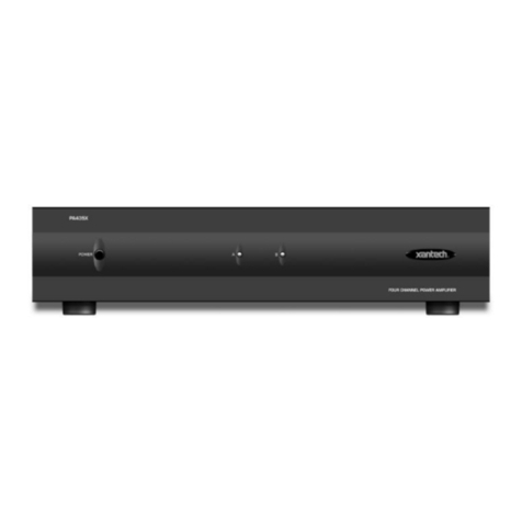
Xantech PA635X User manual

Xantech

Xantech PA635X User manual

Xantech PA4100X User manual

Xantech

Xantech PA4100X User manual

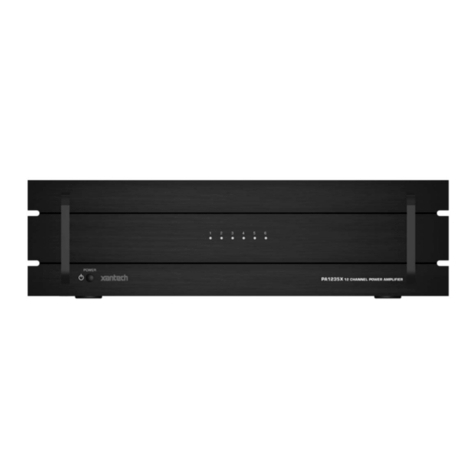
Xantech PA1235X User manual

Xantech

Xantech PA1235X User manual

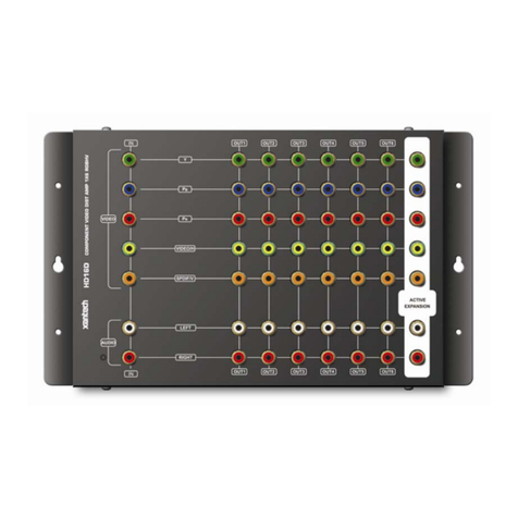
Xantech HD16D User manual

Xantech

Xantech HD16D User manual

Xantech PA640 User manual

Xantech

Xantech PA640 User manual

Xantech BXAUDIO4X4 User manual

Xantech

Xantech BXAUDIO4X4 User manual

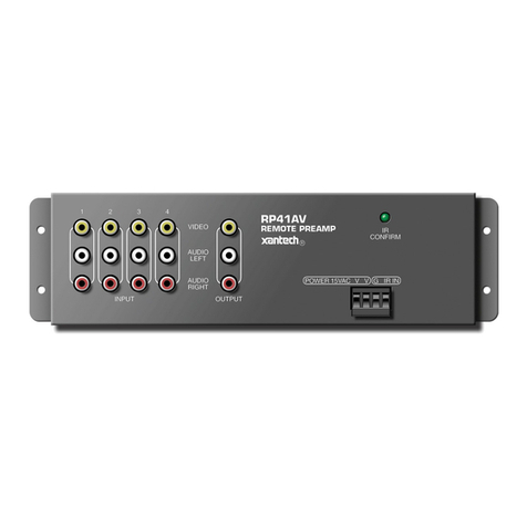
Xantech RP41AV User manual

Xantech

Xantech RP41AV User manual

Xantech MRC88 User manual

Xantech

Xantech MRC88 User manual

Xantech CA1250 User manual

Xantech

Xantech CA1250 User manual

Xantech MRC44 User manual

Xantech

Xantech MRC44 User manual

Xantech AV-61 User manual

Xantech

Xantech AV-61 User manual

Xantech MRC88 User manual

Xantech

Xantech MRC88 User manual

Xantech D5RHK Instruction Manual

Xantech

Xantech D5RHK Instruction Manual

Xantech PA1235 User manual

Xantech

Xantech PA1235 User manual

Xantech PA1235X User manual

Xantech

Xantech PA1235X User manual

Xantech PA635 User manual

Xantech

Xantech PA635 User manual

Xantech AV61 User manual

Xantech

Xantech AV61 User manual

Xantech MX88 User manual

Xantech

Xantech MX88 User manual

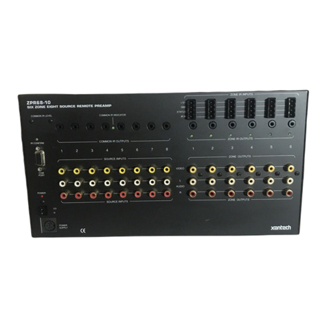
Xantech ZPR68-10 User manual

Xantech

Xantech ZPR68-10 User manual

Xantech ZPR68-10 User guide

Xantech

Xantech ZPR68-10 User guide

Xantech PA435X User manual

Xantech

Xantech PA435X User manual

Popular Amplifier manuals by other brands

Hama PA-506 operating instructions

Hama

Hama PA-506 operating instructions

AUSTRALIAN MONITOR XA1000 Installation and operation manual

AUSTRALIAN MONITOR

AUSTRALIAN MONITOR XA1000 Installation and operation manual

Avaya HIS user guide

Avaya

Avaya HIS user guide

Fender Tone Master Deluxe Reverb user manual

Fender

Fender Tone Master Deluxe Reverb user manual

Analog Metric EL34 SE user manual

Analog Metric

Analog Metric EL34 SE user manual

Behringer TUBE ULTRAGAIN MIC200 user manual

Behringer

Behringer TUBE ULTRAGAIN MIC200 user manual

MTX TH90.2 manual

MTX

MTX TH90.2 manual

AUSTRALIAN MONITOR AMC120 Service information

AUSTRALIAN MONITOR

AUSTRALIAN MONITOR AMC120 Service information

Triax TMB 100S Mounting instruction

Triax

Triax TMB 100S Mounting instruction

Kicker CX300.4 owner's manual

Kicker

Kicker CX300.4 owner's manual

Crown Micro-Tech MT-2400 supplementary guide

Crown

Crown Micro-Tech MT-2400 supplementary guide

ALLNIC AUDIO L-5000 DHT owner's manual

ALLNIC AUDIO

ALLNIC AUDIO L-5000 DHT owner's manual

Cambridge Audio Azur 540A user manual

Cambridge Audio

Cambridge Audio Azur 540A user manual

North Star Design Incanto operating manual

North Star Design

North Star Design Incanto operating manual

Art PRO CHANNEL II Service manual

Art

Art PRO CHANNEL II Service manual

Pioneer PRS-D2000SPL - Premier Amplifier owner's manual

Pioneer

Pioneer PRS-D2000SPL - Premier Amplifier owner's manual

Halcro DM38 owner's manual

Halcro

Halcro DM38 owner's manual

Sugar Bytes Vocodizer manual

Sugar Bytes

Sugar Bytes Vocodizer manual

manuals.online logo
manuals.online logoBrands
  • About & Mission
  • Contact us
  • Privacy Policy
  • Terms and Conditions

Copyright 2025 Manuals.Online. All Rights Reserved.