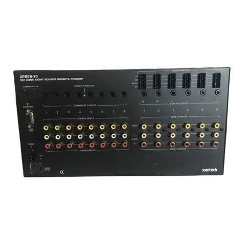
Xantech ZPR68-10 User guide

ApplicationAdvisory
*DATE*
Page 1 of 8
AssembliesAffected:
ZPR68-10
Type:
RS232 PROTOCOL
Date:
October 14, 1999
PRELIMINARY DOCUMENT
This document reflects the changes made since the ZPR68-10 instructions were written.
The changes in the microprocessor code are related to the following areas:
1 - data transmitted and received via the RS232 serial port
2 - settings after recovery from power shutdown
3 - state of C.O. after serial port commands
1 - RS-232 DATA
The code affecting the data transmitted and received via the RS232 serial port has been
modified in three areas and a new data display mode has been added.
First, the code has been modified so that no characters are returned when sending
commands except a + and no query characters are returned except the "answer value"
and a CR(carriage return). This change allows the RS232 link to operate without dealing
with the delay between individual ASCII characters which previously was required.
Second, a flag has been added which can be set and reset by the IR input and queried
and reset via the RS232 serial port. This flag operates independently of all other
functions and is intended for use as an indicator of some function external to the ZPR68-
10 such as a warning device.
Third, the volume can now be incremented or decremented via the RS232 serial port.
The new data display mode causes the ZPR68-10 to send status data to any device
connected to the serial port whenever an IR command is received. This data can be
displayed on a monitor or other device or can be used to log activity.
The ZPR68-10 has a bidirectional data interface which allows control and reading of all
functions by a personal computer, "dumb" terminal or other device. The ZPR68-10 will
communicate with an RS232-type serial port configured for 9600 baud, 8 data bits, 1
stop bit, no parity, full duplex and no handshaking. Raw ASCII data is interchanged.
Only three lines of the RS232 port are utilized, transmit data, receive data and data
ground.
In order to communicate with the ZPR68-10 using a personal computer, you will need a
communications program such as Procomm for the PC or ZTerm for the Macintosh.
Configure the program for 9600 baud, 8 data bits, 1 stop bit, no parity, full duplex and no
handshaking. Determine which port you are going to use to communicate with the
ZPR68-10 and configure the program for that port (COM1 or COM2 on the PC, MODEM

ApplicationAdvisory
*DATE*
Page 2 of 8
or PRINTER on the Macintosh). On the PC, you will probably have a mouse plugged into
one port, usually COM1. You will then have to use COM2 for the ZPR68-10.
With the cable plugged into the selected serial port and the ZPR68-10, turn everything
on and run the program. Lock the CAPS LOCK key on your keyboard. Type the following
keys, one-at-a-time, do not press ENTER or RETURN:
?01V= [question-mark, zero, one, capital-vee, equals-sign]
The monitor will show a two digit number between 00 and 40 followed by a CR. For
example 35CR. If there is a communications problem, the monitor will show a hyphen
and a carriage return - CR.
What is the significance of all of these characters? In ?01V 25CR, the ?indicates that
we are querying the ZPR68-10. We are determining what it is set to. The 01 indicates
that we want to know something about output zone 1. The Vindicates that we are
interested in the volume level. The ZPR68-10 responds that the level is 25. And, finally,
the CR indicates that the data bits exchanged are correct. If there is a communications
problem, the ZPR68-10 will respond with a - CR.
QUERIES
The output zones on a ZPR68-10 are factory preset 01 through 06 and EXP9 output
zones are factory preset 07 through 15. They can, however, be programmed for other
two-digit numbers as outlined in appendix 1.
The functions which can be queried, in addition to the volume (V), are the treble (T), the
bass (B), the input source number (I), the state of the STATUSterminal on the four-pin
ZONE CONTROL - IR INPUT connector(C), the mute (M), and the flag (A).
Two digit numbers are used to indicate volume level and tone control settings. The
volume and tone levels change at 2dB per step. The numbers are related to level in dB
as shown in the examples in these tables-
VOLUME LEVEL (40 steps)

ApplicationAdvisory
*DATE*
Page 3 of 8
TREBLE AND BASS LEVELS (24 steps)
The query form, ?01V=, returns a two-digit answer for volume, ?01T=, treble and
?01B=, bass, as shown above. The query ?01I= returns a single digit, one through eight,
indicating the number of the input source.
If you query the status, ?01C=, it will return an N if the status is off or a Yif the status is
on.
If you query the mute, ?01M=, it will return an Nif the mute is off. In other words, the
mute is off if the audio is on. The query will return a Yif the mute is on (the audio is off).
DATA QUERY
The DATA query causes the ZPR68-10 to return a string of ASCII characters as outlined
below. Type Z01 for the data string for zone 1. The DATA query is the only one which
does not require a ?or an =.

ApplicationAdvisory
*DATE*
Page 4 of 8
The ZPR68-10 will respond to any IR command by returning data via the serial port. The
response occurs approximately one second after the last IR command is received. Data
is returned only for the zone or zones which have received an IR command. Global IR
commands will cause data to be returned for all zones. An "empty" global IR command
consisting of the GLOBAL button followed by the ADJ-OFF button will cause data to be
returned for all zones without causing anything to change.
DATA FORMAT
Data is sent as a string of ASCII characters. The first string in any group of strings, is
preceeded by a line-feed (0Ah), a carraige-return (0Dh) and a bell (07h) and each string
is followed by a line-feed (0Ah) and a carraige-return (0Dh). If more than one string is
sent, the second and subsequent strings are preceeded by a bell (07h) and each string
is followed by a line-feed (0Ah) and a carraige-return (0Dh).
Each string consists of 13 data fields. Each data field consists of one, two or three ASCII
data characters followed by a tab (09h).The order of the fields in each string is as
follows:
FIELD RANGE RANGE IN ASCII CODE
ZONE 01-15 30h31h-31h35h
INPUT 01-08 30h31h-30h38h
TRIM SETTING 00-06 30h30h-30h36h
VOLUME 00-40 30h30h-34h30h
BALANCE P/S 10L-00C-10R 31h30h4Ch-30h30h43h-31h30h52h
BALANCE 10L-00C-10R 31h30h4Ch-30h30h43h-31h30h52h
TREBLE P/S 00-06-12 30h30h-30h36h-31h32h
TREBLE 00-06-12 30h30h-30h36h-31h32h
BASS P/S 00-06-12 30h30h-30h36h-31h32h
BASS 00-06-12 30h30h-30h36h-31h32h
STATUS 0, 1 30h, 31h
MUTE 0, 1 30h, 31h
VOLUME MAX 00-40 30h30h-34h30h
The ZONE field indicates which zone is being reported by the string. The string reports
the INPUT selection, the volume level TRIM setting (see page 265 of the Xantech
Applications Manual 1998 or the ZPR68-10 Instructions), the VOLUME setting, the
BALANCE PreSet setting, the BALANCE setting, the TREBLE PreSet setting, the
TREBLE setting, and the BASS PreSet setting, the BASS setting. The STATUS field
indicates the condition of the STATUS terminal on the four-pin ZONE CONTROL - IR
INPUT connector. The MUTE field is not a simple indications of the IR MUTE function. It

ApplicationAdvisory
*DATE*
Page 5 of 8
is the logical-OR of the IR MUTE command and the QUIET (Q) serial port command. If
either is set, then the MUTE field is equal to 1 (one). If neither is set, then the MUTE field
is equal to 0 (zero). The VOLUME MAX field indicates the maximum volume preset
level.
COMMANDS
To send a command to the ZPR68-10, use an !(exclamation-point) instead of a ?
(question-mark). Try this example- To select source input 2 by zone 4, type !04I2+
(exclamation-point, zero, four, capital-eye, two, plus). The ZPR68-10 will return and the
monitor will display +.
Once an input is selected, it can be changed by repeating the Icommand sequence
using a different number for the source input. The audio and the status can be shut-off
by using the Ccommand. For example, to shut-off the audio and the status of zone 4
type !04CN+. To turn them back on, you must reselect the input by typing !04I2+. You
cannot use !04CY+. It doesn't do anything. The video is not affected by the Ccommand.
To set the volume of zone 4 to the maximum level, type !04V40+. The number following
the V corresponds to the attenuation values shown in the table above.
To increment the volume of zone 5 one 2dB step, type !05LU+. To decrement the
volume of zone 5 one 2dB step, type !05LD+.
There are two ways to mute the audio without affecting the video. First, the volume can
be set to zero by sending !04V00+. To return to the previous volume level, type the
original volume level command, !04V40+, again.
The second way is to use the Q(quiet) command. Type !04QY+ to quiet the zone and
!04QN+ to restore the audio. Note that the Qcommand is not the same function as the
Mor mute. The Qcan only be used as a command with an !and cannot be used as a
query with a ?. The Mcan only be used as a query with a ?and cannot be used as a
command with an !. Their is no way to check the status of quiet (Q). There is no way to
control the status of mute (M) via the digital interface. It can only be controlled via the
infrared input by a hand-held remote or a keypad.
To set the treble of zone 4 to flat response, type !04T06+. The number following the T
corresponds to the amplification/attenuation values shown in the table above. To set the
bass of zone 4 to flat response, type !04B06+.
GLOBAL COMMANDS
You can send global commands to control all zones at the same time. The only change
from the previous examples is the use of 00 as the zone number. !00CN+ will shut off all
zones. !00QY+ will quiet all zones and !00QN+ will restore all zones.
ApplicationAdvisory
*DATE*
Page 6 of 8
If you send !00V30+, all zones will have a volume setting of 30 (-20dB). All tone settings
will be set to flat by sending !00T06+ and !00B06+.
You can select the same input source for all zones by sending !00I3+. All zones will now
have source 3 as their input.
To set the flag, use the Abutton located in the upper left-hand corner of the RC68
programmer. To reset the flag, use the Bbutton of the RC68 or type !A. Note that a +is
not sent with this command. The flag is an indicator of its condition only. It does not
affect any other functon of the ZPR68-10.
GLOBAL QUERIES
The DATA query causes the ZPR68-10 to return a string of ASCII characters as outlined
in the DATA QUERY section. Type Z00 for the data string for all zones. Note that the
DATA query does not require a ?or an =.
To query the flag type ?A. A Ywill be returned if the flag has been set or an Nwill be
returned if it has been reset. Note that an =is not used with this query.
Global queries, except for data and flag, are not supported.
2 - POWER SHUTDOWN RECOVERY
All settings are restored upon recovery from an AC Power shutdown. The volume level
does not reset to a default value, it resets to the level to which is was set before the
power was shutdown.
3 - C.O. STATE
If a zone has been muted and its C.O. is off, a change in volume, bass, treble or balance
will un-mute the zone and turn the C.O. on.
APPENDIX 1 - HEX VALUES FOR ASCII CHARACTERS
ASCII CHARACTER HEX CODE
CARRAIGE RETURN 0D
LINE FEED 0A
BELL 07
EXCLAMATION (!) 21
PLUS (+) 2B
HYPHEN (-) 2D

ApplicationAdvisory
*DATE*
Page 7 of 8
EQUALS (=) 3D
QUESTION (?) 3F
DIGITS 0-9 30-39
A 41
B 42
C 43
D 44
I 49
L 4C
M 4D
N 4E
Q 51
T 54
U 55
V 56
Y 59
Z 5A
APPENDIX 2 - ZPR68-10 ZONE NUMBER PROGRAMMING
NOTE - All zone cards are programmed when they are installed at the factory. If it
becomes necessary to change the number, follow the procedure outlined below.
TO SET THE ZONE NUMBER
1 - Connect an IR receiver to that zone.
2 - Set the switches on the rear of a Xantech RC68 or RC68+ Programmer to FE.
3 - Using the table, select the button for the number desired. For example, to set the
zone to respond to 03, press the button marked 90. The zone now is identified as 03.
4 - Be sure to reset the switches on the programmer to anything other than FE or FF!
RC-68
01-10 20-48 02-01 03-90
N/U 05-C0 06-50 07-D0
04-40 09-A0 10-30 11-B0
08-20 13-E0 14-70 15-F0

ApplicationAdvisory
*DATE*
Page 8 of 8
12-60 17-88 18-18 19-98
16-08 25-A8 26-38 27-B8
24-28 29-E8 30-78 31-F8
28-68 21-C8 22-58 23-D8
RC-68+
01-
80 20-
48 02-
10 03-
90 64-
01
00-
00 05-
C0 06-
50 07-
D0 68-
41
04-
40 09-
A0 10-
30 11-
B0 72-
21
08-
20 13-
E0 14-
70 15-
F0 76-
61
12-
60 17-
88 18-
18 19-
98 80-
09
16-
08 25-
A8 26-
38 27-
B8 88-
29
24-
28 29-
E8 30-
78 31-
F8 92-
69
28-
68 21-
C8 22-
58 23-
D8 84-
49
77-
E1 81-
89 85-
C9 89-
A9 93-
E9
78-
71 82-
19 86-
59 90-
39 94-
79
79-
F1 83-
99 87-
D9 91-
B9 95-
F9
Other manuals for ZPR68-10
1
Table of contents
Other Xantech Amplifier manuals

Xantech
Xantech MRC88 User manual

Xantech
Xantech PA635X User manual

Xantech
Xantech PA4100X User manual

Xantech
Xantech MRC88 User manual

Xantech
Xantech CA1250 User manual

Xantech
Xantech ZPR68-10 User manual

Xantech
Xantech D5RHK Instruction Manual

Xantech
Xantech MRC44 User manual

Xantech
Xantech RP41AV User manual

Xantech
Xantech MRC88 User manual

Xantech
Xantech HD16D User manual

Xantech
Xantech BXAUDIO4X4 User manual

Xantech
Xantech 792-10 User manual

Xantech
Xantech PA1235 User manual

Xantech
Xantech PA435X User manual

Xantech
Xantech AV-61 User manual

Xantech
Xantech PA635 User manual

Xantech
Xantech PA1235X User manual

Xantech
Xantech AV61 User manual

Xantech
Xantech PA640 User manual