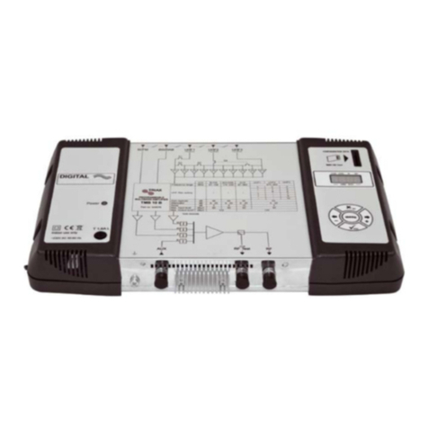
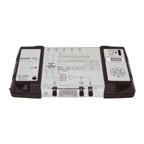
Triax TMB 100S User guide

Programmable Multiband Amplifier
TMB 100 ¤ TMB 100S
1
Programmable Multiband Amplifier
TMB 100 &TMB 100S
Mounting instruction
July 2014 –V1.0

Programmable Multiband Amplifier
TMB 100 ¤ TMB 100S
2
General information ......................................................................................................................3
Safety instructions........................................................................................................................3
Installing the unit...........................................................................................................................4
Programming the unit ...................................................................................................................5
Configuring the unit......................................................................................................................6
Operating principle..................................................................................................................6
Menus :...................................................................................................................................6
Flow chart......................................................................................................................................7
Menus ............................................................................................................................................8
Config menu................................................................................................................................8
Configuration of filter distribution .................................................................................................8
Input amplifiers setting.................................................................................................................9
Selection of remote power supply voltage....................................................................................9
Remote power supply setup......................................................................................................10
LTE function.............................................................................................................................10
Import and export menu ............................................................................................................11
PIN Code..................................................................................................................................12
Language selection and Temperature display............................................................................12
UHF filters setup. ......................................................................................................................13
Setting the levels.......................................................................................................................14
AGC..........................................................................................................................................15
Auto level..................................................................................................................................15
SAT Menu.................................................................................................................................16
TMB 100 Diagram........................................................................................................................17
Technical Specifications.............................................................................................................18
Notes............................................................................................................................................19

Programmable Multiband Amplifier
TMB 100 ¤ TMB 100S
3
G
G
Ge
e
en
n
ne
e
er
r
ra
a
al
l
l
i
i
in
n
nf
f
fo
o
or
r
rm
m
ma
a
at
t
ti
i
io
o
on
n
n
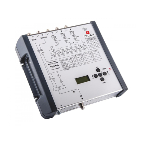
The processing units in the TMB100 range are used to selectively filter digital and analogue UHF
channels. These units also couple and amplify VHF programmes according to the satellite band
model (IF).
TMB100 units have 10 UHF filters, distributed over 3 inputs with programmable bandwidth from 1 to
7 channels (8 to 56 MHz), making it suitable for most situations.
An individual setting for each filter or frequency band, and automatic control of the UHF output level,
for aligning service plan levels.
TMB-100 part nr. 360223
5 inputs: BI + FM, BIII-DAB, UHF1, UHF2, UHF3
Gain UHF = 55 / 35 dB
Gain BIII = 45 dB
Gain BI-FM = 30 dB
Output level UHF = 117 dBµV
TMB-100S part nr. 324580
6 inputs: BI + FM, BIII, UHF1, UHF2, UHF3, BIS
Gain Sat-IF = 40 dB
Gain UHF = 55 / 35 dB
Gain BIII = 45 dB
Gain BI-FM = 30 dB
Output level SAT = 118 dBµV
Output level UHF = 115 dBµV
S
S
Sa
a
af
f
fe
e
et
t
ty
y
y
i
i
in
n
ns
s
st
t
tr
r
ru
u
uc
c
ct
t
ti
i
io
o
on
n
ns
s
s
Important: The unit should only be opened by a qualified technician.
Disconnect the unit before carrying out any work on it, as some powered components are
dangerous (risk of electrical shock).
To maintain the temperature of the unit within its normal operating range, ensure the free
circulation of air around the unit (avoid placing it in enclosed spaces). The ventilation grids
must be free of any obstruction.
Ensure that no liquids can penetrate inside the unit (splashes and/or run off).
Do not install the unit in a damp place. If there are traces of condensation on the unit, do not
use it until it has dried completely.
The mains power cable and the HF connection cables must be in good condition and free to
move (neither crushed nor obstructed).
The mains plug, easily accessible for the technician, must be out of reach of children.
Grounding of the unit
Your aerial installation must comply with the requirements specified by the European
provisions EN 50083 (conformity of collective installations) and EN 60065 (standards in
force for electrical protection).
Replacing fuses
Only a qualified technician can replace defective fuses.
Electromagnetic compatibility (EMC)
Ensure that the screws on the box are properly tightened.
Cables and connection terminals should show no signs of rust.
Programmable Multiband Amplifier
TMB 100 ¤ TMB 100S
4
I
I
In
n
ns
s
st
t
ta
a
al
l
ll
l
li
i
in
n
ng
g
g
t
t
th
h
he
e
e
u
u
un
n
ni
i
it
t
t
We recommend you install the unit in a sufficiently ventilated place. Natural ventilation must be able
to occur through the ventilation grids; leave a minimum space of 15 cm around the unit to ensure
maximum ventilation. When installing or cabling the unit, we recommend you disconnect the
mains power cable.
Connecting the unit
Note: UHF inputs are remotely supplied and protected against short circuits. The power available is
12 or 24V, 50mA max. The preamplifier is detected automatically; only the remote power voltage
can be programmed.
Output
Entradas
UHF1, UHF2,
UHF3
Entrée
BI/FM
Conector
Datos
IMPORT-
EXPORT
Entrada
BIII/DA
B
Sat input
Keypad
Display
Inputs BI-FM BIII UHF Interface RS232
Earthing
connector

Programmable Multiband Amplifier
TMB 100 ¤ TMB 100S
5
P
P
Pr
r
ro
o
og
g
gr
r
ra
a
am
m
mm
m
mi
i
in
n
ng
g
g
t
t
th
h
he
e
e
u
u
un
n
ni
i
it
t
t
A 4-digit display and a keypad are all you need to programme the unit. Follow the procedure below
for configuring the various parameters.
When the unit is powered on:
the programme mode is in standby:
by default, the system is configured as follows:
oUHF1 3 UHF filters
oUHF2 0 UHF filters
oUHF3 7 UHF filters
all the UHF filters are deactivated (display "- -"),
the attenuators are at zero.
Factory reset
If necessary, to revert to factory settings, follow the procedure below:
1. Disconnect the power cable
2. Press the esc button and hold it
3. Connect the power cable
The unit erases all the programming parameters, including the PIN code, and switches to standby
mode.
You can release the esc button when the display shows "Default Settings".
- Running through the menus ,
- Decrement the value "-"
Back to previous menu (^)
Save the value (V)
- scrolling through the menus ,
- Increment the value "+"

Programmable Multiband Amplifier
TMB 100 ¤ TMB 100S
6
C
C
Co
o
on
n
nf
f
fi
i
ig
g
gu
u
ur
r
ri
i
in
n
ng
g
g
t
t
th
h
he
e
e
u
u
un
n
ni
i
it
t
t
On powering on, the unit is in standby mode, a light segments flashes across the display.
Operating principle
To access the configuration menus, press a button
To summarize:
To scroll through the menus, use the + / - buttons.
To enter a menu, press enter.
To exit a menu, press the esc button
Press the Menu button to have a quick access to the CONFIG menu
Note:
If the button is not pressed for one minute, the unit switches to standby mode.
Menus :
BOOTLOAD
V.12a43
BOOTLOAD
No SD!
WAIT ..
=
<CONFIG> < CHAN > < SAT >< AUTO >< GAIN >
p
p
p
p
p
p
p
p
p
p
Standby mode; push a button to
reach the CONFIG menu SAT Menu
Only on TMB 100S
Power on!
CONFIG menu UHF channel
setup Gain setup AGC &
AutoLevel setup

Programmable Multiband Amplifier
TMB 100 ¤ TMB 100S
7
F
F
Fl
l
lo
o
ow
w
w
c
c
ch
h
ha
a
ar
r
rt
t
t

Programmable Multiband Amplifier
TMB 100 ¤ TMB 100S
8
M
M
Me
e
en
n
nu
u
us
s
s
Config menu.
This menu allows:
Configuration of filter distribution on UHF1, 2 and 3 inputs. Comb 0010
Switch on/off the input amplifiers Ampx on/off
Selection of remote power supply (12 or 24 VDC). 12 or 24 VDC
Select the remote power for the UHF inputs VDCx on/off
To limit the UHF channels at channel 60 LTE on / off
Import or export a configuration file Import/Export
Activate the PIN code menu
Select the language Ang/Esp
Display the internal temperature
Enter
Enter
CONFIG
Comb 0010 CONFIG
Vdc 12V CONFIG
LTE on CONFIG
Export
CONFIG
Import CONFIG
PIN off CONFIG
Lang eng CONFIG
54°C
CONFIG
Comb 0010
p
p
p
p
p
p
p
p
p
p
p
p
p
p
p
p
CONFIG
Amp3 on/off
CONFIG
Amp2 on/off
CONFIG
Amp3 on
CONFIG
Amp2 on
CONFIG
Amp1 on/off
CONFIG
Amp1 on
Enter
Enter
p
p
Enter
CONFIG
Vdc 12V/24V
Enter
p
p
p
p
CONFIG
Vdc3 on/off
CONFIG
Vdc2 on/off
CONFIG
Vdc3 off
CONFIG
Vdc2 off
CONFIG
Vdc1 on/off
CONFIG
Vdc1 off
Enter
Enter
p
p
Enter
CONFIG
LTE on/off
Enter
p
p
Enter
Enter
p
p
CONFIG
NoSD!/SE001
Enter
Enter
p
p
CONFIG
Ex: SE 000
Enter
CONFIG
PIN on/off
Enter
p
p
CONFIG
PIN 2312
p
p
Enter
p
p
p
p
Enter
p
p
SE 000
SE 000
SE 000
Enter Enter
CONFIG
Lang eng/spa
Enter
p
p
PIN 2312
esc esc esc esc esc esc esc esc esc esc
Configuration of filter distribution
Unit in standby mode, push a button to reach the CONFIG menu.
Press the enter button to reach the Comb menu.
Press enter again to change the configuration of the UHF inputs (part of the
display flashes)
Press the buttons + or - to select the distribution of the filters over the UHF inputs.
Confirm by pressing enter
Notes:
Each UHF filter can be deactivated. Just configure the filter in question to the value "off".
=
<CONFIG>
Enter
Enter
Enter
CONFIG
Comb 0010
CONFIG
Comb 0010
p
p
Input UHF1 UHF2 UHF3
3 5 2
1 7 2
0 8 2
3 0 7
1 0 9
0 0 10
Number of filters per
UHF input

Programmable Multiband Amplifier
TMB 100 ¤ TMB 100S
9
Input amplifier setting.
<CONFIG>
Enter
Enter
Enter
CONFIG
Comb 0010
CONFIG
Comb 0010
p
p
CONFIG
Amp1 on/off
CONFIG
Amp1 on
Enter
Enter
p
p
p
p
p
p
CONFIG
Amp2 on CONFIG
Amp3 on
p
p
CONFIG
Amp2 on/off
Enter
Enter
p
p
CONFIG
Amp3 on/off
Enter
Enter
p
p
Unit in standby mode, push a button to reach the CONFIG menu.
Press the enter button to select the Comb menu.
Press the button to reach the AmpX menu.
Press enter to activate the menu
Press the buttons + or - to change the configuration of the UHF input amplifiers (on/off)
Confirm by pressing enter
Selection of remote power supply voltage.
Unit in standby mode, push a button to reach the CONFIG menu.
Press the enter button to select the Comb menu.
Press the button 2 times to reach Vdcx menu.
Press the enter to activate the menu
Press the buttons + or - to select the Voltage (12 or 24 VDC)
Confirm by pressing enter
Enter
Enter
CONFIG
Comb 0010 CONFIG
Vdc 12V
CONFIG
Comb 0010
p
p
Enter
CONFIG
Vdc 12V/24V
Enter
p
p
p
<CONFIG>
Enter 2x

Programmable Multiband Amplifier
TMB 100 ¤ TMB 100S
10
Remote power supply setup.
Enter
Enter
CONFIG
Comb 0010 CONFIG
Vdc 12V
CONFIG
Comb 0010
p
p
p
p
CONFIG
Amp3 on/off
CONFIG
Amp2 on/off
CONFIG
Amp3 on
CONFIG
Amp2 on
CONFIG
Amp1 on/off
CONFIG
Amp1 on
Enter
Enter
p
p
Enter
CONFIG
Vdc 12V/24V
Enter
p
p
p
p
<CONFIG>
Enter
CONFIG
VDC1 on/off
CONFIG
VDC1 off
Enter
Enter
p
p
p
p
p
p
CONFIG
VDC2 on CONFIG
VDC3 on
p
p
CONFIG
VDC2 on/off
Enter
Enter
p
p
CONFIG
VDC3 on/off
Enter
Enter
p
p
Unit in standby mode, push a button to reach the CONFIG menu.
Press the enter button to select the Comb menu.
Press the button 3 times to reach VDCx menu.
Press enter to activate the menu
Press the buttons + or - to change the configuration (on/off)
Confirm by pressing enter
Press the button to reach the other inputs and repeat the process..
LTE function
This function limits the filter setting on channel 60.
<CONFIG>
Enter
Enter
Enter
CONFIG
Comb 0010
CONFIG
Comb 0010
p
p
p
CONFIG
LTE on
Enter
CONFIG
LTE on/off
Enter
p
p
X times
Unit in standby mode, push a button to reach the CONFIG menu.
Press the enter button to select the Comb menu.
Press the several times to reach LTE menu.
Press enter to activate the menu
Press the buttons + or - to change the configuration (on/off)
Confirm by pressing enter
LTE = off 21 - 60

Programmable Multiband Amplifier
TMB 100 ¤ TMB 100S
11
Import and export menu
CONFIG
Export
CONFIG
Import
p
p
p
Enter
Enter
p
p
CONFIG
NoSD!/SE001
Enter
p
p
CONFIG
Ex: SE 000
Enter
<CONFIG>
Enter
Enter
Enter
CONFIG
Comb 0010
CONFIG
Comb 0010
p
p
p
p
CONFIG
Ex: SE 000
Enter
p
p
CONFIG
Ex: SE 000
Enter
X times
Unit in standby mode, push a button to reach the CONFIG menu.
Press the enter button to select the Comb menu.
Press the several times to reach Import or Export menu.
Press enter to activate the menu
Press the buttons + or - to select the file (SE00x)
Confirm by pressing enter
The TMB units are equiped with RS232 interface, please used an RS232/SD adapter to store your
configuration files.
Important.
When using these menus and no SD card is available the display shows NoSD.
The SD/MMC card should be in FAT16 format. Files should be in root directory.

Programmable Multiband Amplifier
TMB 100 ¤ TMB 100S
12
PIN Code
CONFIG
PIN off
CONFIG
PIN on/off
Enter
p
p
CONFIG
PIN 2312
p
p
Enter
Enter
PIN 2312
<CONFIG>
Enter
Enter
Enter
CONFIG
Comb 0010
CONFIG
Comb 0010
p
p
p
X times
Unit in standby mode, push a button to reach the CONFIG menu.
Press the enter button to select the Comb menu.
Press the several times to reach PIN menu.
Press enter to activate the menu
Press the buttons + or - to change the configuration (on/off)
Confirm by pressing enter
Choose your PIN code (only if on is selected)
oPress enter to activate the menu
oPress the buttons + or - to change the number
oConfirm by pressing enter
oDo the same for the other digits
Language selection and Temperature display
<CONFIG>
Enter
Enter
CONFIG
Comb 0010
CONFIG
Comb 0010
p
p
p
X times CONFIG
Lang eng CONFIG
54°C
p
p
Enter
CONFIG
Lang eng/spa
Enter
p
p
p
p
Enter
Default PIN code: 2312

Programmable Multiband Amplifier
TMB 100 ¤ TMB 100S
13
UHF filters setup.
Unit in standby mode, push a button to reach the CONFIG menu.
Press the button to reach the CHAN menu.
Press enter to activate the menu
Press enter again to setup the UHF filter
Press the buttons + or - to select the start channel
Confirm by pressing enter
Press the buttons + or - to select the end channel
Confirm by pressing enter
Press the button to setup the next channel
Notice:
The number of filter is according to the configuration of filter distribution
In LTE mode = off only channel 21 to 60 are available.
=
CHAN
xP off
CHAN
3P off
CHAN
1P off
Enter
Enter
Enter
p
p
CHAN
1P 21-21 When channel is
always used Err
Enter
p
p
CHAN
1P 21-21
p
p
CHAN
2P off
<CONFIG>
p
p
< CHAN >

Programmable Multiband Amplifier
TMB 100 ¤ TMB 100S
14
Setting the levels.
There are three types of level setting:
“Manual” setting of output levels (Gain menu)
automatic alignment of UHF filter output levels to a value entered by the user. (Auto menu,
sub-menu Level)
automatic UHF gain control (Menu Auto, sub-menu AGC)
Unit in standby mode, push a button to reach the CONFIG menu.
Press the button several times to reach the Gain menu.
Press enter to activate the menu
Press the or button to setup the VHF, UHF or Filter gain
Confirm by pressing enter
Press the buttons + or - to change the value
Confirm by pressing enter
Press the or button to setup the next gain
< GAIN > < GAIN >
nP off / 0..20
GAIN
1P off
Enter
p
p
p
p
GAIN
UHF 20 GAIN
VHF 20
p
p
GAIN
UHF 0..20 GAIN
VHF 0..20
Enter Enter
Enter
p
p
Enter
p
p
GAIN
FM 20
p
p
GAIN
FM 0..20
Enter
Enter
p
p
Enter
Notice:
The number of filter is according to the on/off filter setting

Programmable Multiband Amplifier
TMB 100 ¤ TMB 100S
15
AGC
Unit in standby mode, push a button to reach the CONFIG menu.
Press the button several times to reach the Auto/AGC menu.
Press enter to activate the AGC menu
Press the buttons + or - to change the value
Confirm by pressing enter
Press the buttons + or - to change the value
Confirm by pressing enter
Auto level
Unit in standby mode, push a button to reach the CONFIG menu.
Press the button several times to reach the Auto/Level menu.
Press enter to activate the Level menu
Press the buttons + or - to change the value
Confirm by pressing enter
Press the buttons + or - to change the value
Confirm by pressing enter
< AUTO > AUTO
AGC off
Enter
Enter
p
p
AUTO
AGC off/on
AUTO
Level 117
Enter
Enter
p
p
AUTO
Level 117
Enter
AUTO
LevPx 6
p
p
IMPORTANT!
AGC: The unit memorizes the average output level. A variation of ± 1 dB triggers the
function and compensates the variation within gain and attenuation limits
AGC mode hides all other menus. To modify the parameters, switch the AGC mode to OFF.
Auto Level: The unit memorizes the selected output level, the function try to reach the value
within input, gain and attenuation limits.
Note: Setting of the levels BI-II / BIII is not automatic.

Programmable Multiband Amplifier
TMB 100 ¤ TMB 100S
16
SAT Menu
TMB 100S models have one IF amplification path. The Sat menu is used to configure the remote
power supply of the LNB (OFF / 13 /17 VDC), to activate the 22kHz generator and the 9dB equalizer.
Unit in standby mode, push a button to reach the CONFIG menu.
Press the button several times to reach the SAT menu.
Press enter to activate the SAT menu
Press the or button to select the Supp, Gain, Eq, Pol or Band menu.
oSupp (power on or off)
oGain
oEq (Equalizer 0dB_off or 9dB_on)
oPol (H or V polarization)
oBand (Lo/H Band)
Press enter to activate the selected menu
Press the buttons + or - to change the value
Confirm by pressing enter
< SAT > Enter
Enter
Enter
SAT
Supp off
p
p
SAT
Supp off/on
p
p
Enter
Enter
SAT
Gain 20
p
p
SAT Gain
0..20
p
p
Enter
Enter
SAT
Eq off
p
p
SAT
Eq off/on
p
p
0 / 9dB
Enter
Enter
SAT
Pol off
p
p
SAT
Pol H/V
p
p
Enter
Enter
SAT
Band Lo
p
p
SAT
Band Lo/Hi

Programmable Multiband Amplifier
TMB 100 ¤ TMB 100S
17
T
T
TM
M
MB
B
B
1
1
10
0
00
0
0S
S
S
D
D
Di
i
ia
a
ag
g
gr
r
ra
a
am
m
m
S1
0/12/24V
0/12/24V
BI/FM
UHF1
VHF
UHF3
OUT
S2
S3
P
1
P
9
P
8
P
7
P
6
P
5
P
4
P
3
P
2
P1
0
SU3
SU1
AGC
0-20dB
0/12/24V
UHF2
S4
SU2
0/9dB
SAT
0-20dB
0-20dB
0-20dB
0-20dB
0/13/17V
0/22kHz

Programmable Multiband Amplifier
TMB 100 ¤ TMB 100S
18
T
T
Te
e
ec
c
ch
h
hn
n
ni
i
ic
c
ca
a
al
l
l
S
S
Sp
p
pe
e
ec
c
ci
i
if
f
fi
i
ic
c
ca
a
at
t
ti
i
io
o
on
n
ns
s
s
Type
Part nr. Units
Number of inputs
AMPLIFICATION Max. BI_FM / BIII / UHF / SAT input level dB
BI/FM gain dB
BIII gain dB
UHF gain dB
SAT gain dB
Preacc. Sat input
FM / BIII / UHF / SAT Noise Factor dB
Attenuator per input dB
Global UHF attenuator dB
Max. Output level VHF/UHF (IM3-52dB) / SAT (IM3 -35 dBc) dBµV
Max. Output level VHF/UHF (IM2-60dB) dBµV
FILTERING UHF filter distribution UHF1 / UHF2 / UHF3 3 5 2 3 5 2
1 7 2 1 7 2
- 8 2 - 8 2
3 - 7 3 - 7
1 - 9 1 - 9
- - 10 - - 10
Width of filtering channels MHz
Filter selectivity @ ± 10 MHz dB
Input return loss dB
output return loss dB
Operating conditions
Power supply (50-60 Hz)
power consumption at 230VAC W
remote supply UHF 1, 2 ou 3 V / mA
Input equiped with remote supply
LNB power supply V / mA
22 kHz generator on Sat input
Operating temperature °C
MECANICS Input/output connectors
Dimensions (H xW x D) mm
UHF 1, 2 et 3
8 à 56
10
> 10
0 à 20
0 à 20
120 / 117 / -
230 VAC
24
12 ou 24 / 80
-5 à +40
> 10
90 / 80 / 95 / -
30
45
55 / 35
9 / 5 / 7 / -
120 / 120 / 115 / 118
8 à 56
12 ou 24 / 80
0, 13 ou 17
ON / OFF
10
> 10
27
UHF 1, 2 et 3
6
TMB 100
360223
TMB 100S
324580
8
55 / 35
30
45
90 / 80 / 95 / 80
-5 à +40
"F" femelles
360 x 225 x 50
9 (switchable)
40
0 à 20
9 / 5 / 7 / 6
0 à 20
> 10
230 VAC

Programmable Multiband Amplifier
TMB 100 ¤ TMB 100S
19
N
N
No
o
ot
t
te
e
es
s
s
_________________________________________________
_________________________________________________
_________________________________________________
_________________________________________________
_________________________________________________
_________________________________________________
_________________________________________________
_________________________________________________
_________________________________________________
_________________________________________________
_________________________________________________
_________________________________________________
_________________________________________________
_________________________________________________
_________________________________________________
_________________________________________________
_________________________________________________
_________________________________________________
_________________________________________________
_________________________________________________
_________________________________________________
_________________________________________________
_________________________________________________
_________________________________________________
_________________________________________________
_________________________________________________
_________________________________________________
_________________________________________________
_________________________________________________
_________________________________________________
_________________________________________________
_________________________________________________
_________________________________________________

Amplificateurs programmables
TMB 100 & TMB 100S
1
Programmable Multiband Amplifier
TMB 100 &TMB 100S
Manual
July 2014 –V1.0
TRIAX
This manual suits for next models
1
Table of contents
Other Triax Amplifier manuals

Triax
Triax GNS 20 User manual

Triax
Triax IFA288 User manual

Triax
Triax GPV 950 Series User manual

Triax
Triax 892288 User manual

Triax
Triax TSWA User manual

Triax
Triax TMB 100 User manual

Triax
Triax GHV 500 Series User manual

Triax
Triax CGSD 162 User manual

Triax
Triax HDA 1x8S User manual

Triax
Triax TMB 10A User guide

Triax
Triax GPV 150 Series User manual

Triax
Triax GHV 12 204 Series User manual

Triax
Triax GHV 900 Series User manual

Triax
Triax 324575 User manual

Triax
Triax TMB 200S User manual

Triax
Triax HDA 1x2S4K User manual

Triax
Triax CGA 225 User manual

Triax
Triax GNS 34 User manual

Triax
Triax IFM 120 User manual

Triax
Triax ECO T5 User manual