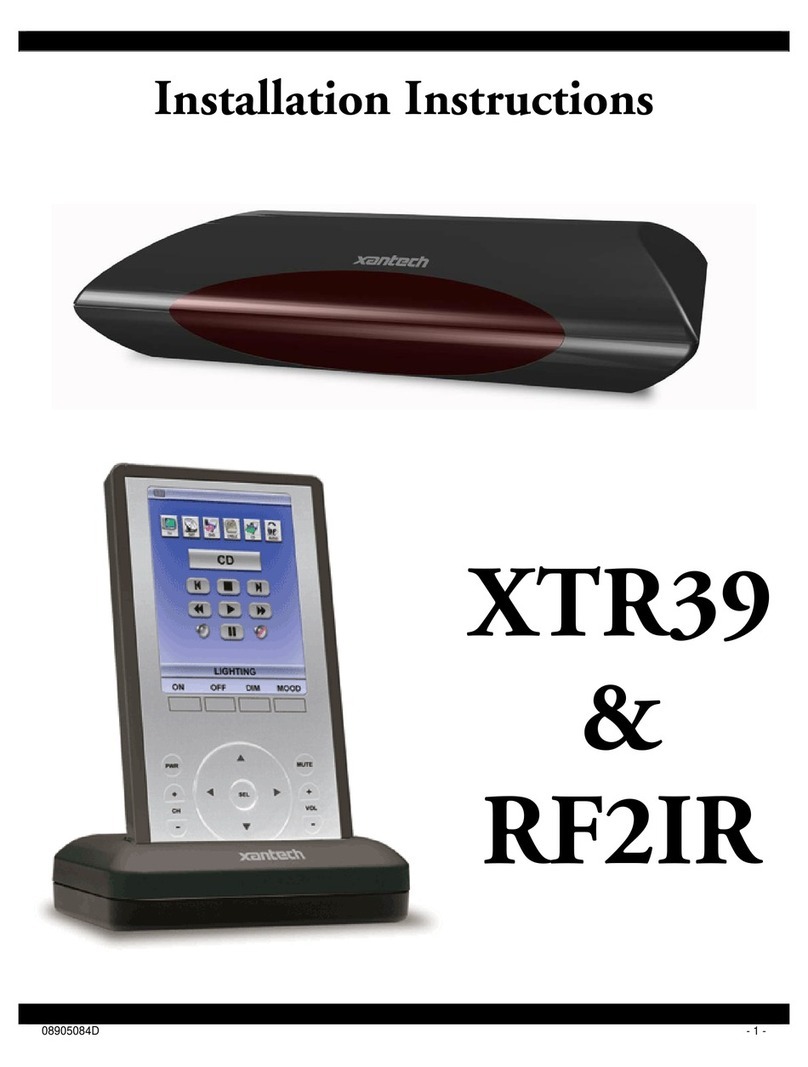
Xantech XTR39 User manual

- 1 -
XTR39
Hand-Held LCD Remote Control
Installation Instructions

- 2 -
ATTENTION:
The XTR39 is shipped with the battery disconnected.
You must connect the battery.
To ensure proper connection between the XTR39 remote and
docking cradle, follow the docking procedure.

- 3 -
INTRODUCTION ..................................................................................................................................5
XTR39 Overview..................................................................................................................................................................................5
XTR39 Features....................................................................................................................................................................................5
Box Contents.........................................................................................................................................................................................5
XTR39 Diagram....................................................................................................................................................................................6
Charging Cradle Diagram.....................................................................................................................................................................7
PRELIMINARY SETUP.........................................................................................................................7
Connecting the Battery Pack.................................................................................................................................................................7
Charging the XTR39 and Charging Cradle LED Indicator...................................................................................................................8
SYSTEM SETUP..................................................................................................................................................................................8
Touch-screen Calibration Adjustment.................................................................................................................................................10
Touch-screen Calibration Test............................................................................................................................................................10
PROGRAMMING SETUP...................................................................................................................11
XTR39 Dragon™ Installation Guide..................................................................................................................................................11
INSTALLING AND CONFIGURING THE XTR39 DRAGON™ SOFTWARE ......................................16
Starting XTR39 Dragon™ Software...................................................................................................................................................16
USB Connection .................................................................................................................................................................................16
Configuring USB Port.........................................................................................................................................................................17
Verifying PC to XTR39 Communication............................................................................................................................................19
STARTING A PROJECT.....................................................................................................................20
CREATING THE GRAPHICAL USER INTERFACE (GUI)..................................................................21
Choosing A Style ................................................................................................................................................................................22
Building a Page (Working with GTL’s)..............................................................................................................................................22
Placing Source GTL’s.........................................................................................................................................................................22
Placing Function Button GTL’s..........................................................................................................................................................23
Inserting Additional Pages for a Single Source...................................................................................................................................24
Editing GTL Properties.......................................................................................................................................................................25
Creating Labels (GuiFX Transports and Icons)..................................................................................................................................26
Inserting Labels...................................................................................................................................................................................28
LEARNING IR COMMANDS (CREATING PALETTE FILES).............................................................28
Built-In IR Code Library.....................................................................................................................................................................29
Testing IR Commands in the IR Library.............................................................................................................................................30
Learning IR Commands (XIR2)..........................................................................................................................................................31
Using the Palette Editor ......................................................................................................................................................................31
Editing Function Names in the Palette Editor.....................................................................................................................................33
Testing IR Commands in the Palette Editor........................................................................................................................................33
Creating a Palette File.........................................................................................................................................................................34
- 4 -
PLACING COMMANDS ONTO THE GTL’S (CREATING MACRO’S)................................................34
Selecting IR Palettes ...........................................................................................................................................................................35
Associating Commands To GTL’s (Drag And Drop Commands)......................................................................................................35
Timed Delays......................................................................................................................................................................................36
Delete..................................................................................................................................................................................................36
Testing Commands Placed on the virtual XTR39 Window................................................................................................................36
TRANSFERRING THE PROJECT......................................................................................................37
Firmware Update.................................................................................................................................................................................38
Cleaning the XTR39 ...........................................................................................................................................................................38
Rechargeable Battery Maintenance.....................................................................................................................................................38
FCC NOTICE......................................................................................................................................39
ACCESSORY ITEMS .........................................................................................................................40
WARRANTY INFORMATION .............................................................................................................40

- 5 -
INTRODUCTION
XTR39 Overview
The XTR39 Color LCD touch-screen remote control from Xantech is the perfect solution to the clutter
of difficult-to-use remote controls that accompany most home theater systems.
The XTR39 is a stylish, simple-to-use remote control that can be personalized via its vivid full color
3.9” touch-screen display: button layout can be customized; easily identified icons created for virtually
any function or command; and multiple screen pages allow less frequently used buttons to be
concealed.
Pick it up, and the XTR39 comes to life. Dedicated buttons for the most frequently used buttons such
as volume, channel, power, and mute are perfectly positioned. A convenient touch-wheel control sets
the XTR39 apart, allowing quick scrolling through menus and commands.
All screen buttons and icons can be programmed to perform multiple commands with a single touch.
Additionally, the XTR39 can be configured to control nearly any major system in the home such as
A/V system, lighting, climate control, and more.
The XTR39 can be programmed with the same functions and screen appearance as all other Xantech
SPLCD SmartPad LCD™ in-wall touchpanels installed in the home, for consistency and simple
operation.
XTR39 Features
Vivid 3.9” Color LCD touch-screen display
Fully customizable screen graphics and functions
Capable of controlling virtually every major home system
Hard buttons for frequently used commands
Four easy access programmable macro buttons
Touch-wheel control for quick scrolling through menus and commands
Eight megabyte internal memory
RF capable remote
Long-life rechargeable Lithium-Ion battery with battery status indicator and charging stand
Programmed via Xantech’s XTR39 Dragon Drop-IR™ programming software
Uses same graphics and commands as SPLCD SmartPad LCD™ in-wall touchpanels
Box Contents
XTR39 Hand-Held LCD Remote Control
Lithium-Ion Rechargeable Battery
Charging Cradle
Charging Cradle Power Supply (+5VDC, 2Amp)
XTR39 Dragon Drop-IR Software
Instruction Manual

- 6 -
XTR39 Diagram
Docking
Cradle
Connector
Programmable
Cursor
Buttons
USB
Programming
Port
Programmable
Function
Buttons
Programmable
Function
Buttons
Vivid 3.9
Touc screen
Display
Dual IR Emitters
IR Learn Eye
Programmable
Function
Buttons
XTR39 Front View
Note: Simulated graphics.

- 7 -
Charging Cradle Diagram
Charging Cradle Front View Charging Cradle Rear View
PRELIMINARY SETUP
Connecting the Battery Pack
Battery Cover
Release Tab
Serial Number
Battery Connector
Installed

- 8 -
Charging the XTR39 and Charging Cradle LED Indicator
Plug the included power supply into the charging cradle. Then plug the power supply into a power
receptacle. The Charging Cradle LED will blink an ‘orange’ color 3 times. This indicates the Charging
Cradle is ready for use.
Making sure the battery has been installed (see ‘Connecting the Battery Pack’), place the XTR39 on
the charging cradle. The XTR39 must be charged at least 10 hours straight without being used. Not
doing so may harm the life span of the battery.
When the XTR39 is placed on the Charging Cradle, the LED indicator will be either ‘red’ or ‘green’.
•A ‘red’ LED indicates that the XTR39 battery is charging.
•A ‘green’ LED indicates that the XTR39 battery is charged and ready for use.
Battery Indicator (Touch-screen)
•The XTR39 also has a battery strength indicator. A completely filled in battery icon indicates a
fully charged battery.
SYSTEM SETUP
Entering and Exiting the Setup Page
Specific settings can be adjusted on the XTR39
directly. To enter the Display Settings mode, press
and hold the “MUTE” button for 5 seconds. A new
“XTR39 SETUP” screen will appear.

- 9 -
(1) Display Settings - Backlight Adjustment
Touch and drag the slider to adjust the XTR39 to a
desired backlight brightness level.
(2) Display Settings - Contrast Adjustment
Touch and drag the slider to adjust the XTR39 to a
desired contrast level.
(3) Display Settings - Backlight Timeout
Press “LESS” or “MORE” button to select the desired
backlight timeout. This determines the amount of
time, in seconds, when the backlight will turn off after
the XTR39 is no longer is use. Timeout can be set
between 5 seconds and 30 seconds.
(1) System Settings - Audio Feedback
The XTR39 can emit a distinctive ‘beep’ that
indicates when any button or GTL (Graphical Touch-
Link) is pressed. This allows the XTR39 to provide
feedback that a button has been pressed. The ‘beep’
sounds can be enabled or disabled by pressing the
button. Every press toggles between ‘on’ and ‘off’.
(2) System Settings - Motion Detect
The XTR39 can detect motion when it is being
handled by a user. This allows the XTR39 to turn on
the backlight to the touch-screen without having to
use the touch-screen or any buttons. The motion
detect can be enabled or disabled by pressing the
button. Every press toggles between ‘on’ and ‘off’.
.

- 10 -
(1) System Information
The XTR39 can display the firmware version and
project information.
The top displays the system firmware version.
The bottom displays the IR library version.
Touch-screen Calibration Adjustment
The accuracy of triggering a Hot-Spot associated to a GTL (Graphical Touch-Link) can be calibrated.
It is advised to use a PDA stylus for increased precision.
1. From the “XTR39 Setup” page, press the down-arrow to enter calibration adjustment mode.
2. A black dot on an all-white background will appear. Using a PDA stylus or your smallest finger,
press the black dot and release.
3. Another black-dot will appear. Press the black dot and release.
4. Again, another black-dot will appear. Press the black dot and release.
5. A total of three calibration points appear. Now press anywhere on the touch-screen and a
black dot will appear in that exact location.
6. Wait for the unit to exit calibration mode by doing nothing for 10 seconds.
Touch-screen Calibration Test
The accuracy of the triggering a Hot-Spot associated to a GTL (Graphical Touch-Link) can be tested.
It is advised to use a PDA stylus for increased precision.
1. From the “XTR39 Setup” page, press the up-arrow to enter calibration adjustment mode.
2. To enter the “XTR39 Setup” page, press and hold the “MUTE” button for 5 seconds.
3. Press anywhere on the touch-screen and a black dot will appear in that exact location.

- 11 -
PROGRAMMING SETUP
XTR39 Dragon™ Installation Guide
This guide provides users with step by step instructions on how to install the XTR39 Dragon™
software.
Requirements:
•1.0 GHz or greater processor (CPU)
•Windows 2000 and Windows XP
•650 MB Hard Drive space (you will need more as your libraries and projects expand)
•256 MB RAM (512MB preferred)
•Mouse, Keyboard, USB port
Installation
1. Place the Installation CD-ROM into the computer CD or DVD drive. The CD-ROM will auto-run
and the menu, as seen below, will appear. Press the “Install XTR39 Dragon Version 1.0”
button.

- 12 -
2. The installation process will begin:
Note: If you do not have the Microsoft .NET (dotnetfx.exe) or InstallShield update on your computer,
this will get installed first.
3. Click on the Next button:

- 13 -
4. Enter your name and company and select if the installation should only be available to you or
to anyone else who may log into your computer, then click Next:
5. The default installation path for XTR39 Dragon™ is ‘C:\Program Files\Xantech\XTR39
Dragon\’, if this is acceptable click Next. Otherwise click on the Change button and enter the
location you wish to install XTR39 Dragon™:

- 14 -
7. The installation will proceed showing the user the current Status:
8. After installation is complete. Click on the Finish button. (Make sure to leave the ‘Yes, check
for program update (Recommended) after the setup completes” in order to ensure that you
have the latest version of XTR39 Dragon™ installed:

- 15 -
9. The installation package will ask you to reboot your computer. Click Yes so that the installation
process can be completed. If any other applications are open, be sure to save your work.
9. After your computer reboots, the installation package will check to make sure that you have the
latest version of XTR39 Dragon™ on your computer.
10. You can now run the XTR39 Dragon™ software by double clicking the shortcut on your desktop:
Or select XTR39 Dragon™ from your start menu under the Xantech start folder
(Start -> Programs -> Xantech).

- 16 -
CONFIGURING THE XTR39 Dragon™ SOFTWARE
Starting XTR39 Dragon™ Software
After the successful installation of the software, double-click the XTR39 Dragon™ icon on your
desktop or:
1. From START menu, choose Programs.
2. Select Xantech and click on the XTR39 Dragon™ Icon from the menu.
3. The program loads and opens to the following XTR39 Dragon™ opening screen.
XTR39 Dragon™ Opening Screen
USB Connection
Open the access cover on the XTR39 and pivot the cover down. Connect the wide end of the
included USB cable to the USB port of your PC and the small end to the connector on the lower end
of the XTR39 unit (next to the docking cradle connector).
NOTE: The USB connection requires a ‘B’ Type connector to interface with the XTR39. USB cable is
included with the XTR39.
When the XTR39 is connected to the Computer USB, the backlight will remain on. There is no
backlight timeout.

- 17 -
Configuring USB Port
To configure the USB Port for the first time, complete the following instructions:
1. Connect the XTR39 to the computer via the USB port. Under Windows XP, a Found New
Hardware Wizard window asking to connect to Windows Update will appear. Select “No, not
this time” and click “Next”.
2. The wizard will ask what to do next. Select “Install the software automatically” and click “Next”.
Be sure the XTR39 Dragon CD-ROM is in the computer. This is where the USB drivers reside.

- 18 -
3. A list of USB drivers will be displayed. Select the driver that applies with the computer’s
operating system. For Windows XP, select the driver found in the “7202XP” folder. For
Windows 2000, select the driver found in the “7202w2k” folder. Click “Next”.
4. The XTR39 is now connected to the computer and can be programmed with XTR39 Dragon.
Click “Finish” to exit the Found New Hardware Wizard.

- 19 -
Programming the XTR39 system is a two-step process:
Creating the GUI (Graphical User Interface) Screens.
Assigning functions (macros) to the GTL’s (Graphical Touch Links) to control external devices.
Through XTR39 Dragon™ Software, both of these tasks are easily performed. The software contains
built-in Style libraries for creating the GUI screens as well as IR-Code libraries for programming each
of the GTL’s. This makes programming the XTR39 a very quick and easy process.
Verifying PC to XTR39 Communication
(“Who Am I” Base Unit Version Verification)
Before continuing, it is recommended to verify proper communication between the PC and the
XTR39. This can be done by performing a “Who Am I…” function.
1. Connect the XTR39 to the computer via a USB cable (included).
2. Open the XTR39 Dragon application as previously described.
3. Click on the Base Unit Menu and select Who Am I… and then XTR39
4. A window will appear displaying the XTR firmware version.
5. Click OK to complete the verification.
Note: If a message is returned stating: “Unable to Determine Base Unit” this could be due to the
following:
1. The XTR39 is not powered ON. Please check the power state of the unit.
2. There is a communication error between the PC and the XTR39. Please verify the USB cable
is properly connected to the unit. When the USB cable is plugged into the PC and the XTR39,
the backlight on the XTR39 will stay on (no backlight timeout).

- 20 -
STARTING A PROJECT
With the XTR39 Dragon™ software open and the COM PORT communication verified proceed as
follows:
From the File menu choose “NEW PROJECT” (CTRL+N) or choose “OPEN PROJECT” (CTRL+O) to
modify an existing project file. You may also use the NEW PROJECT or OPEN PROJECT icons
located on the Tool Bar at the top of the page.
SPLCD Graphic Page Edit Screen
Save
New
Project Open Grid
ON/OFF Snap to
Grid Grid
Color
Grid
Size
Other manuals for XTR39
1
Table of contents
Other Xantech Remote Control manuals

Xantech
Xantech RC68 Plus User manual

Xantech
Xantech URC-2 User manual

Xantech
Xantech MAC1 User manual

Xantech
Xantech RGC11 User manual

Xantech
Xantech SR21 User manual

Xantech
Xantech XTRALINK IP User manual

Xantech
Xantech XVC100 User manual

Xantech
Xantech XTR39 User manual

Xantech
Xantech MRCREMRP User manual

Xantech
Xantech INJ94 User manual