Xantech 291-00 KIT User manual

IR Receivers & Modems
1
INSTALLATION INSTRUCTIONS
291-00 KIT
HIDDEN LINKTM IR REPEATER SYSTEM
The 291-KIT is a prepackaged infrared repeater system. It includes a 291-00 IR Receiver, a 789-44
Connecting Block, a 781RG Power Supply and four 283M Blink-IR™ Mouse Emitters. These parts are all
that are necessary to control up to four components. The 291-KIT is intended for use in IR control systems
where the 789-44 Connecting Block is within reach of the 7-foot cable of the 291-00 ... as when installing
the 291-KIT in a cabinet where the controlled components are behind closed doors.
A typical system is shown in Fig. 1 below. Refer to this diagram and the procedure that follows when making
connections:
1. Attach the 283M Emitters onto the IR Sensor Windows of the components in your system that you wish
to control. Refer to Figs. 1 & 2.
2. Plug the mini plugs of the 283M's into the "EMITTERS" jacks of the 789-44 Connecting Block.
3. Locate the 291-00 IR Receiver in a location outside of the equipment cabinet or closet that will have
a straight line-of-sight view of your Hand Held Remote(s).
4. Plug the mini-plug of the 291-00 into the "IR RCVR" jack on the 789-44 Connecting Block.
5. Plug the 781RG Power Supply into an unswitched 120 VAC outlet.
NOTE: It is important that you use an unswitched AC outlet so that the IR system is always active for
system power ON commands.
6. Plug the "C" plug of the 781RG Power Supply into the "12VDC" jack on the 789-44 Connecting Block.
The IR repeater system should now operate each of the controlled components. When the system is
operating correctly, you should see a red "talk-back" LED flash on the front of the 291-00 when you aim your
hand held remote control(s) at it and press the buttons.
A/V Receiver
Satellite Rec'r
291-00 Hidden Link™
IR Receiver Hand Held
Remote
Equipment
Mounted
Behind Closed
Cabinet Doors
To 120 V AC
(unswitched)
781RG
Power Supply
789-44
Connecting Block
283M
Blink-IR
CABINET, EQUIPMENT ROOM, ETC.
CD Changer
CONTROLLED
COMPONENTS
VCR
IR Sensor Window
Mini-Plugs
"C" Plug
7' Cable with
3-Conductor
Mini Plug
Optional cable
to IR Receivers
or Keypads in
other rooms
(not included)
283M
Blink-IR™
Mouse Emitter
283M
Blink-IR
283M
Blink-IR
12VDC
+12 VDC
GND
STATUS
IR IN
EMITTERS
IR
RCVR
789-44
CONNECTING BLOCK
®
283M
Emitter
Housing
Clear adhesive layer.
(Replace, when necessary,
with a short piece of two-
sided adhesive tape, supplied).
Mini-wire
lead
Peel back and remove the
protective cover from the
adhesive layer. Press adhesive
side to the IR Sensor Window
on the Controlled Component.
Fig. 2 Removing adhesive protective cover
Fig. 1 The 291-10 Kit used in a typical IR repeater System.

2291 KIT
291-00 IR RECEIVER SPECIFICATIONS
• Infrared modulation frequency bandwidth: 30 - 100 kHz.
NOTE: Unit will not work with certain brands & models that operate at higher frequencies. Contact
Xantech Technical Support for more information.
• Reception range: Up to 30 feet, depending on local conditions and remote control used.
• Reception angle: 45 degrees off axis.
• Cable requirements for long lengths to remote rooms: 3-conductor/24 gauge solid or stranded wire up
to 200', 22 gauge up to 600', 20 gauge up to 2000' and 18 gauge up to 5000' (unshielded OK).
• Maximum transmission length: One mile with 18 gauge wire.
• Talkback LED (red). Indicates infrared reception only when emitter(s) are connected.
• Maximum number of directly driven IR emitters: 4 single or 4 dual emitters using the 789-44 Connecting
Block.
• Up to twelve 291's may be connected in parallel at the screw terminals input of Xantech connecting blocks.
• Power requirements: 12 volts DC @ 10 mA. Requires 781RG Power Supply (included).
• Dimensions: 3-1/4" x 1" x 2".
TROUBLE SHOOTING
1. In some locations, stray interference may prevent proper operation. Examples of such interference:
•Fluorescent, Compact Fluorescent, Neon or Halogen lights, Neon Art, and light dimmers.
•Plasma Screen Television.
•Direct or reflected sunlight.
•Infrared security sensors (active types).
•RF radiation from TV sets that may be close to the 291-00 IR Receiver.
2. You can confirm the source of the interference by temporarily turning off TV sets, isolating the
291-00 Receiver from all sunlight and turning off all lights, light dimmers and Infrared security systems.
Then check to see if the 291-00 operates the component.
•Sometimes interference will cause the red Talk-Back LED on the front of the 291-00 to blink dimly,
intermittently, or continuously.
•
The Talk-Back LED should only blink when you are sending infrared commands to the 291-00
from a remote control!
•It may be necessary to move either the interfering source or the 291-00 IR receiver to achieve proper
operation.
3. If the red Talk-Back LED or the 283M Emitters do not blink when you are sending IR commands to
the 291-00 from a remote control, check the following:
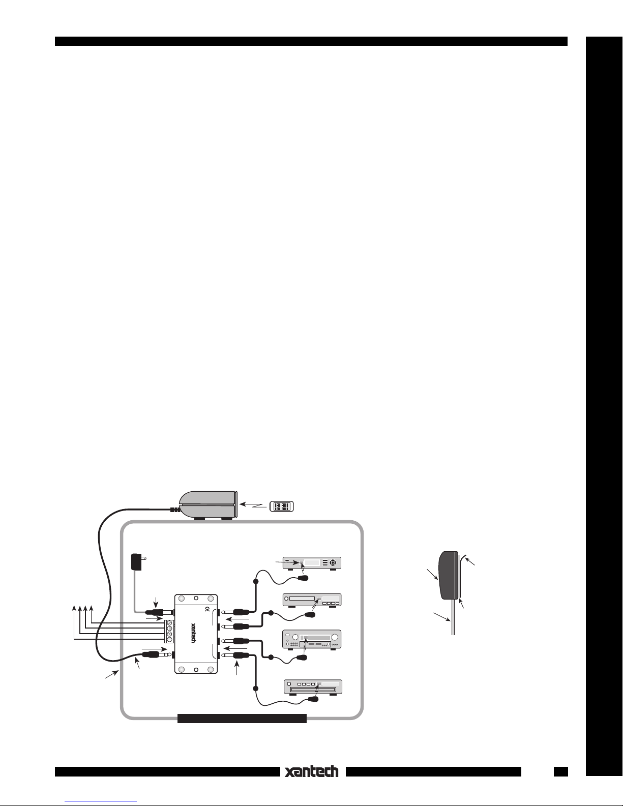
•Make sure the 781RG power supply is plugged securely into a live 120V AC outlet.
•Be sure the stereo mini plug of the 291-00 IR Receiver is plugged into the "IR RCVR" jack on the
789-44 Connecting Block,
not
into one of the "EMITTERS" jacks.
•Check to see that all the 283M mini plugs are properly seated into the "EMITTERS" jacks on the
789-44 Connecting Block.
4. If the 283M Emitters blink, but the component does not respond, reposition the 283M Emitter(s). They
may not be located directly over the component’s infrared receiving "window". Consult owner's
manual of component or the manufacturer for exact location of the infrared "window".
5. If the system still does not work, contact the dealer from whom you purchased the 291-KIT, or contact
XANTECH Technical Support at 800-843-5465, ext. 812.
4-10-00
This manual suits for next models
1
Table of contents
Popular Repeater manuals by other brands

Define Instruments
Define Instruments P2P-R General information

Satel
Satel micra MRU-300 Quick installation guide

Black Box
Black Box AC3010A quick start guide

Silvercrest
Silvercrest SWV 300 C1 User manual and service information

B meters
B meters RFM-RPT-3 Quick user guide

Icom
Icom UHF FM Repeater iFR6100 instruction manual