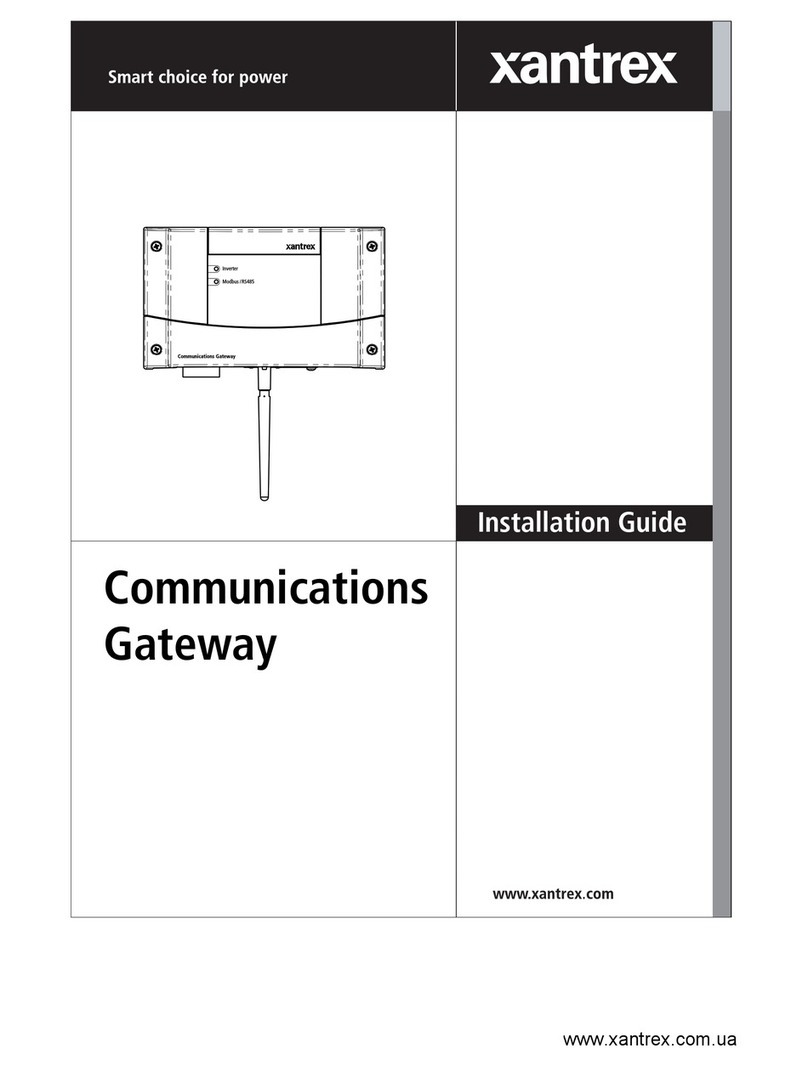
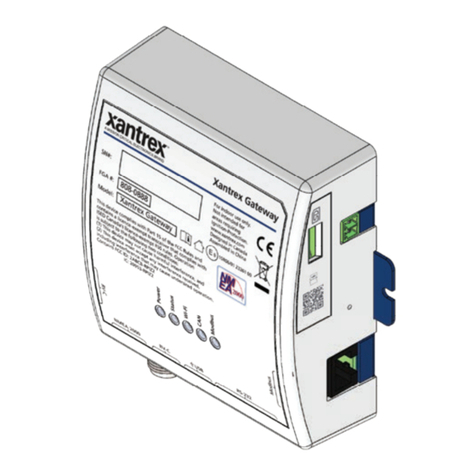
Xantrex Communications gateway User manual

Communications
Gateway
Installation Guide
Communications Gateway
Inverter
Modbus /RS485


Communications Gateway
Installation Guide

About Xantrex
Xantrex Technology Inc. is a world-leading supplier of advanced power electronics and controls with
products ranging from small mobile units to utility-scale systems for wind, solar, batteries, fuel cells,
microturbines, and backup power applications in both grid-connected and stand-alone systems. Xantrex
products include inverters, battery chargers, programmable power supplies, and variable speed drives
that convert, supply, control, clean, and distribute electrical power.
Trademarks
Xantrex is a registered trademark of Xantrex International.
Other trademarks, registered trademarks, and product names are the property of their respective owners
and are used herein for identification purposes only.
Notice of Copyright
Communications Gateway Installation Guide © January 2008 Xantrex International. All rights
reserved.
Exclusion for Documentation
UNLESS SPECIFICALLY AGREED TO IN WRITING, XANTREX TECHNOLOGY INC. (“XANTREX”)
(A)MAKES NO WARRANTY AS TO THE ACCURACY, SUFFICIENCY OR SUITABILITY OF ANY TECHNICAL OR
OTHER INFORMATION PROVIDED IN ITS MANUALS OR OTHER DOCUMENTATION.
(B)ASSUMES NO RESPONSIBILITY OR LIABILITY FOR LOSSES, DAMAGES, COSTS OR EXPENSES, WHETHER
SPECIAL, DIRECT, INDIRECT, CONSEQUENTIAL OR INCIDENTAL, WHICH MIGHT ARISE OUT OF THE USE OF
SUCH INFORMATION. THE USE OF ANY SUCH INFORMATION WILL BE ENTIRELY AT THE USER’SRISK; AND
(C)REMINDS YOU THAT IF THIS MANUAL IS IN ANY LANGUAGE OTHER THAN ENGLISH, ALTHOUGH
STEPS HAVE BEEN TAKEN TO MAINTAIN THE ACCURACY OF THE TRANSLATION, THE ACCURACY CANNOT
BE GUARANTEED. APPROVED XANTREX CONTENT IS CONTAINED WITH THE ENGLISH LANGUAGE
VERSION WHICH IS POSTED AT WWW.XANTREX.COM.
Date and Revision
January 2008 Revision B
Part Number
975-0330-01-01
Product Number
865-1055 (North America), 865-1056 (Europe)
Contact Information
Telephone: 1 800 670 0707 (toll free North America)
1 408 987 6030 (direct)
Fax: 1 800 994 7828 (toll free North America)
1 360 925 5143 (direct)
Email: [email protected]
Web: www.xantrex.com

iii
About This Guide
Purpose
This Installation Guide provides explanations and procedures for
installing and configuring the Communications Gateway.
Scope
The Guide provides safety guidelines and procedures for installing and
configuring the Gateway. It does not provide detailed information about
the underlying Xanbus or Modbus protocol.
Audience
The Guide is intended for anyone who needs to install and configure the
Communications Gateway. Installers should be qualified electricians or
service technicians. Once installed, the Gateway can be configured by a
service technician or an end user.
Organization
This Guide is organized into three chapters and one appendix.
Chapter 1, “Introduction” contains information about the features and
functions of the Communications Gateway.
Chapter 2, “Installation” contains information and procedures to install
the Communications Gateway.
Chapter 3, “Configuration” contains information and procedures to
configure the Communications Gateway.
Chapter 4, “Troubleshooting” contains reference information you can
consult if you have problems using the Communications Gateway. This
chapter also lists routers that have been tested with the Gateway.
Note: This manual documents features and operation of the Xantrex base
model Gateway. Gateways installed by second-party service providers (OEMs)
may incorporate modified features and functions that are not described in this
manual.

About This Guide
iv 975-0330-01-01
Appendix A, “Specifications” contains electrical, mechanical and
regulatory specifications for the Communications Gateway.
Conventions Used
The following conventions are used in this guide.
Related Information
You can find more information about Xantrex Technology Inc. as well as
its products and services at www.xantrex.com.
WARNING
Warnings identify conditions or practices that could result in personal injury or
loss of life
CAUTION
Cautions identify conditions or practices that could result in damage to the unit or
other equipment.
Important:
These notes describe things which are important for you to know,
but not as serious as a caution or warning.

v
Important Safety Instructions
General Precautions
1. Before installing and using this device, read all appropriate sections
of this guide and any cautionary markings on the Gateway and the
devices to which it connects.
2. Do not dismantle the Gateway; it contains no user serviceable parts.
3. Protect the Gateway from rain, snow, spray, and water. A
recommended outdoor enclosure is available from Xantrex.
4. Use only accessories recommended or sold by the manufacturer.
Doing otherwise may result in a risk of fire, electric shock, or injury
to persons.
WARNING: Read and save these instructions
This Installation Guide contains important safety and operating instructions.
Before using your Communications Gateway, be sure to read, understand, and
save these safety instructions.
WARNING: Shock and energy hazards
Connecting the Gateway to other equipment may require access to wiring
compartments containing circuits that are shock and/or energy hazards. Refer to
this manual and the manual provided with the other equipment, and to any
warning or caution labels on the equipment. Be sure to disconnect all sources of
power to the equipment before working near its wiring terminals.
Note that in some cases hazardous voltage may still be present at the input to the
equipment, ahead of the disconnecting means. Any guards or barriers provided to
prevent inadvertent contact with live parts must be left in place.
Protection Class III: All circuits in this product are non-hazardous Safety Extra
Low Voltage when connected only to Xanbus or Ethernet networks. Connect
only to the circuit recommended in this manual.

vi 975-0330-01-01
FCC Information to the User
This equipment has been tested and found to comply with the limits for a
Class B digital device, pursuant to part 15 of the FCC Rules. These limits are
designed to provide reasonable protection against harmful interference when
the equipment is operated in a residential environment. This equipment
generates, uses and can radiate radio frequency energy and, if not installed
and used in accordance with the instruction guide, may cause harmful
interference to radio communications. However, there is no guarantee that
interference will not occur in a particular installation. If this equipment does
cause harmful interference to radio or television reception, which can be
determined by turning the equipment off and on, the user is encouraged to try
to correct the interference by one or more of the following measures:
• Reorient or relocate the antenna.
• Increase the separation between the equipment and the receiver.
• Connect the equipment to a circuit different from that to which the
receiver is connected.
• Consult the dealer or an experienced radio/TV technician for help.
This equipment contains a radio transmitter with the following ID numbers:
• FCC: R68WIPORT
• Industry Canada: 2867A-WIPORT
Wireless Networking Security
This device can be configured to connect to the Internet using wireless
technology. As with all such devices, if you do not properly set up a
wireless security system others can get unauthorized access to your
Internet connection and possibly to personal information contained on
your computer network.
Product Recycling
Do not dispose of this product with general household waste!
Electrical appliances marked with the symbol shown must be professionally
treated to recover, reuse, and recycle materials, in order to reduce negative
environmental impact. When the product is no longer usable, European
consumers are legally obligated to ensure that it is collected separately under
the local electronics recycling and treatment scheme.

975-0330-01-01 vii
Important Safety Instructions
- - - - - - - - - - - - - - - - - - - - - - - - - - - - - - - - - - -v
1
Introduction
Gateway Overview - - - - - - - - - - - - - - - - - - - - - - - - - - - - - - - - - - - - - - - - - - - - - 1–2
External Features - - - - - - - - - - - - - - - - - - - - - - - - - - - - - - - - - - - - - - - - - - - - - - 1–3
Types of Gateway Networks- - - - - - - - - - - - - - - - - - - - - - - - - - - - - - - - - - - - - - - 1–5
Local Area Network - - - - - - - - - - - - - - - - - - - - - - - - - - - - - - - - - - - - - - - - - 1–5
Gateway with Remote Access - - - - - - - - - - - - - - - - - - - - - - - - - - - - - - - - - - 1–7
2
Installation
Installing the Gateway- - - - - - - - - - - - - - - - - - - - - - - - - - - - - - - - - - - - - - - - - - - 2–2
Choosing a Location - - - - - - - - - - - - - - - - - - - - - - - - - - - - - - - - - - - - - - - - - 2–3
Materials and Tools Required - - - - - - - - - - - - - - - - - - - - - - - - - - - - - - - - - - - 2–4
Supplied Materials - - - - - - - - - - - - - - - - - - - - - - - - - - - - - - - - - - - - - - - 2–4
Other Materials and Tools - - - - - - - - - - - - - - - - - - - - - - - - - - - - - - - - - - 2–5
Mounting the Gateway - - - - - - - - - - - - - - - - - - - - - - - - - - - - - - - - - - - - - - - 2–5
Connecting the Gateway to a Router or Computer - - - - - - - - - - - - - - - - - - - - - 2–6
Connecting the Gateway to the Xanbus Network - - - - - - - - - - - - - - - - - - - - - - 2–6
Network Layout - - - - - - - - - - - - - - - - - - - - - - - - - - - - - - - - - - - - - - - - - 2–8
Guidelines for Routing the Network Cables - - - - - - - - - - - - - - - - - - - - - - 2–8
Connecting the Gateway to a GT Inverter - - - - - - - - - - - - - - - - - - - - - - - - 2–9
Connecting the Gateway to a XW Hybrid Inverter/Charger - - - - - - - - - - - 2–10
Applying Power to the Gateway - - - - - - - - - - - - - - - - - - - - - - - - - - - - - - - - 2–11
Adding Devices to the Network - - - - - - - - - - - - - - - - - - - - - - - - - - - - - - - - - - - 2–11
Installing Yahoo! Widgets - - - - - - - - - - - - - - - - - - - - - - - - - - - - - - - - - - - - - - - 2–12
3
Configuration
Configuring the Gateway - - - - - - - - - - - - - - - - - - - - - - - - - - - - - - - - - - - - - - - - - 3–2
Viewing the Configuration Web Page - - - - - - - - - - - - - - - - - - - - - - - - - - - - - - - - 3–2
Using the Solar Monitor Widget - - - - - - - - - - - - - - - - - - - - - - - - - - - - - - - - - 3–3
Finding the Gateway IP Address Manually - - - - - - - - - - - - - - - - - - - - - - - - - - 3–5
Finding the Gateway IP Address with No Router in the System - - - - - - - - - - - - 3–7
Contents

Contents
viii 975-0330-01-01
Using the Configuration Web Page - - - - - - - - - - - - - - - - - - - - - - - - - - - - - - - - - - 3–8
Entering Your Basic Information - - - - - - - - - - - - - - - - - - - - - - - - - - - - - - - - 3–9
Renaming Devices - - - - - - - - - - - - - - - - - - - - - - - - - - - - - - - - - - - - - - - - - - 3–9
Configuring the Gateway for Your Network - - - - - - - - - - - - - - - - - - - - - - - - 3–10
Configuring Wireless Mode - - - - - - - - - - - - - - - - - - - - - - - - - - - - - - - - - - - 3–12
Configuring Network Time - - - - - - - - - - - - - - - - - - - - - - - - - - - - - - - - - - - 3–14
Configuring Email - - - - - - - - - - - - - - - - - - - - - - - - - - - - - - - - - - - - - - - - - 3–16
Upgrading Device Firmware - - - - - - - - - - - - - - - - - - - - - - - - - - - - - - - - - - 3–17
Resetting the Gateway to Factory Defaults - - - - - - - - - - - - - - - - - - - - - - - - - - - - 3–19
Power System Monitoring on the Internet- - - - - - - - - - - - - - - - - - - - - - - - - - - - - 3–20
4
Troubleshooting
Device Discovery- - - - - - - - - - - - - - - - - - - - - - - - - - - - - - - - - - - - - - - - - - - - - - 4–2
Loss of Communication - - - - - - - - - - - - - - - - - - - - - - - - - - - - - - - - - - - - - - - - - 4–3
Email Messages - - - - - - - - - - - - - - - - - - - - - - - - - - - - - - - - - - - - - - - - - - - - - - - 4–4
Miscellaneous Issues- - - - - - - - - - - - - - - - - - - - - - - - - - - - - - - - - - - - - - - - - - - - 4–5
Router Compatibility - - - - - - - - - - - - - - - - - - - - - - - - - - - - - - - - - - - - - - - - - - - 4–6
A
Specifications
Electrical Specifications - - - - - - - - - - - - - - - - - - - - - - - - - - - - - - - - - - - - - - - - -A–2
Communication Specifications - - - - - - - - - - - - - - - - - - - - - - - - - - - - - - - - - - - - -A–2
History Data Storage- - - - - - - - - - - - - - - - - - - - - - - - - - - - - - - - - - - - - - - - - - - -A–2
Mechanical Specifications - - - - - - - - - - - - - - - - - - - - - - - - - - - - - - - - - - - - - - - -A–3
Environmental Specifications- - - - - - - - - - - - - - - - - - - - - - - - - - - - - - - - - - - - - -A–4
Regulatory Compliance- - - - - - - - - - - - - - - - - - - - - - - - - - - - - - - - - - - - - - - - - -A–4
Warranty and Return Information
- - - - - - - - - - - - - - - - - - - - - - - - - - - WA–1
Index
- - - - - - - - - - - - - - - - - - - - - - - - - - - - - - - - - - - - - - - - - - - - - - - - - - - - - - - IX–1

1Introduction
Chapter 1, “Introduction” contains information about
the features and functions of the Communications
Gateway.
This chapter covers the following topics:
• “Gateway Overview”
• “External Features”
• “Types of Gateway Networks”

Introduction
1–2 975-0330-01-01
Gateway Overview
The Communications Gateway is the central component for a residential
power monitoring system. The Gateway communicates with Xantrex GT
Solar Inverters and XW Hybrid Inverter/Chargers and transmits a unified
view of system performance to a computer-based power monitoring
application.
On one side, the Gateway directly communicates with a Xantrex inverter
using Xanbus™, a CAN-based network communication protocol
developed by Xantrex. The Gateway converts Xanbus messages to
Modbus messages, and transmits the converted inverter performance data
for monitoring. On the other side, the Gateway’s WiFi/Ethernet module
provides an interface to monitor system performance on a personal
computer. Computer-based monitoring can be performed on your Local
Area Network or using the Internet from any location.
The Gateway features include a standard plug-in WiFi/Ethernet module
with 10/100 Base-T or 802.11b/g, and:
• Embedded web services to support Yahoo! Widgets. Xantrex provides
a Solar Monitor Widget to display data transmitted by the Gateway.
• Embedded web page for configuring the Gateway and upgrading
device firmware.
The Gateway logs and transmits performance data such as:
• Power system energy production
• Individual inverter energy production
• Energy production history—daily, weekly, monthly
• Inverter faults.
To view this production data, you must install the Xantrex Solar Monitor
Widget and configure the Gateway to communicate with your computer
or computer network. Other means of viewing Gateway-transmitted data
will be available from Xantrex in the future. For more information about
Gateway data storage, see “History Data Storage” on page A–2.
Note: The Gateway provides performance data only from the time it is
connected to your power system. The Gateway cannot be calibrated to match
existing power production totals for a power system that has been operating
without a Gateway. When connected to an existing power system, the Gateway
power production totals will differ from the totals displayed by older inverters
or devices in the system.

External Features
975-0330-01-01 1–3
External Features
Figure 1-1
Gateway Front
Item Description
1Inverter LED indicates overall status of the network between the
Gateway and the inverters. The LED blinks in three colors:
•Green: the network is working properly
•Yellow: the Gateway has detected errors on the network
•Red: the Gateway has stopped communicating in the network.
2Modbus/RS485 LED indicates message transmission between the
Gateway and an Internet protocol-connected computer. The LED
blinks during regular operation. The LED is on steadily when the
Gateway is upgrading device software or the Gateway is in bootloader
mode and requires its own software to be loaded. See “Upgrading
Device Firmware” on page 3–17.
3Antenna for the wireless Internet protocol connection.
Communications Gateway
Inverter
Modbus / RS485
1
2
3

Introduction
1–4 975-0330-01-01
Figure 1-2
Gateway Bottom
Item Description
1Inverter (Xanbus RJ-45) ports for connecting the inverter and other
Xanbus devices to the Gateway.
Caution: see “Equipment damage” below.
2Ethernet port for connecting the Gateway to a router or computer.
Caution: see “Equipment damage” below.
3WiFi Antenna.
4Reset button. The Reset button returns the Gateway to its default
settings. See “Resetting the Gateway to Factory Defaults” on page 3–
19.
5RS-485 port for connecting Modbus-equipped devices (do not use—
not supported at this time).
6Zigbee (RJ-11) port (do not use—not supported at this time).
CAUTION: Equipment damage
Although the cables and connectors that connect the Gateway to the Xanbus
network are identical to Ethernet cables and connectors, the communication
interface is not Ethernet. It is based on CAN bus and also supplies the Xanbus
network devices with DC power. The DC power in the Xanbus network is not
compatible with Ethernet. Personal computers or routers may be damaged if
connected directly to powered Gateway Inverter ports. The Gateway can be
damaged if a powered Xanbus cable is connected to the Ethernet port.
Inverter
WARNING!
Not for computer
RS485
Ethernet
Zigbee
12 4563

Types of Gateway Networks
975-0330-01-01 1–5
Types of Gateway Networks
The Gateway can interface with different devices with wired or wireless
connections to provide several options for monitoring your power system
performance.
Local Area Network
The Gateway provides performance data for display on a home computer.
Data is displayed using the Solar Monitor Widget, available free from
Xantrex.
Connections between the Gateway, router and computer can be wired or
wireless, but not both at the same time. An Ethernet connection between
the Gateway and router or computer is required for initial installation and
configuration, after which the Gateway can be set to wireless mode and
the cable removed.
Figure 1-3
Default Wired Network
Xanbus cable
Inverter
Gateway
Router
Home computer
with Widget
Ethernet connection

Introduction
1–6 975-0330-01-01
Figure 1-4
Mixed Wired/Wireless Network 1
Figure 1-5
Mixed Wired/Wireless Network 2
Figure 1-6
Wireless Network With Router
Xanbus cable
Inverter
Gateway
Router
Home computer
with Widget
Ethernet Connection
Wireless Internet Protocol connection
Xanbus cable
Inverter
Gateway
Router
Home computer
with Widget
Ethernet connection Wireless Internet Protocol connection
Xanbus cable
Inverter
Gateway
Router
Home computer
with Widget
Wireless Internet Protocol connection

Types of Gateway Networks
975-0330-01-01 1–7
Gateway with Remote Access
To view power system performance data on a remote computer using the
Internet from any location, you must connect the Gateway to a router and
change your router firewall settings to allow “port forwarding.” Port
forwarding enables a computer from an external IP address (elsewhere on
the Internet) to view Gateway data. Port forwarding allows you to specify
Figure 1-7
Wired Network Without Router
Figure 1-8
Wireless Network Without Router
Important:
Figure 1-7 and Figure 1-8 are “Ad-Hoc” networks that do not
allow access to the Internet. For more information, see “Configuring Wireless
Mode” on page 3–12.
Important:
The wired connections shown in Figure 1-3, Figure 1-5 and
Figure 1-7 are required for initial system configuration.
Xanbus cable
Inverter
Gateway Home computer
with Widget
Ethernet connection
Crossover cable is
required for the
Gateway-to-computer
connection.
Xanbus cable
Inverter
Gateway Home computer
with Widget
Wireless Internet Protocol connection

Introduction
1–8 975-0330-01-01
how and where Gateway data is directed through your router so that you
can view that data from an Internet-connected computer anywhere in the
world.
For more information, see the Gateway configuration web page
(“Viewing the Configuration Web Page” on page 3–2) and “Power
System Monitoring on the Internet” on page 3–20.
If you simply want to monitor your power system on your home network,
you do not need to change your firewall settings.
CAUTION: Computer Security Risk
Changing your router’s firewall settings to allow port forwarding can potentially
leave your home network open to attacks from external computers. Do not
change your firewall settings unless you are absolutely sure of how to do it
correctly. The PORT Forward web site (www.portforward.com) has collected
information on how to configure most popular routers. Xantrex does not provide
any guarantees as to the security of your network if you follow the advice
provided at the PORT Forward web site. Use at your own risk.
Figure 1-9
Gateway with Widget and Remote Access
Inverter
Gateway
Router
Remote computer
with Widget
Xanbus to Gateway EthernetorWirelessInternet
Protocol connection
Internet

2Installation
Chapter 2, “Installation” contains information and
procedures to install the Communications Gateway.
Gateway installation includes mounting the Gateway,
then connecting it to a computer network and to the
Xanbus network.

Installation
2–2 975-0330-01-01
Installing the Gateway
This chapter assumes that one or more inverters are already installed, and
that multiple inverters are already connected with network cables. For
more information about installing a multiple-inverter network, see:
• For GT Inverters: “Communications Wiring for Multiple Inverters” in
the Solar Inverter Owner’s Manual
• For XW Hybrid Inverter/Chargers: The XW Power System
Installation Guide.
Installing the Gateway consists of the following steps:
1. Choosing a Location.
2. Mounting the Gateway.
3. Connecting the Gateway to a router (your local area network) or
computer.
4. Connecting the Gateway to the Xanbus network.
Connecting the Gateway to the Xanbus network also applies power to
the Gateway.
5. Installing Yahoo! Widgets (also known as Konfabulator or Yahoo!
Widget Engine) and Solar Monitor Widget on your computer.
The Solar Monitor Widget displays power system performance data
transmitted from the Gateway.
WARNING: Shock and energy hazards
Connections to other equipment may require accessing wiring compartments
containing circuits that are shock or energy hazards. In such cases, ensure that
sources of power are disconnected. Installation should be done only by a
qualified installer or electrician.
Important:
Apply power to the Gateway only after connecting it to the local
area network in the previous step. This ensures that the Gateway can acquire an
IP address quickly, and does not first acquire a default address that it must reject
after a time-out period.
Table of contents
Other Xantrex Gateway manuals