Xantrex 808-0888 User manual

Xantrex Gateway
Owner's Guide
Xantrex Gateway
808-0888

2 Xantrex Gateway Owner's Guide
Copyright © 2021-2022 Xantrex LLC. All Rights Reserved.
Trademarks are owned by Xantrex LLC and its affiliates. All other
trademarks are owned by their respective companies.
Exclusion for Documentation
UNLESS SPECIFICALLY AGREED TO IN WRITING, SELLER
(A) MAKES NO WARRANTY AS TO THE ACCURACY, SUFFICIENCY OR SUITABILITY OF ANY
TECHNICAL OR OTHER INFORMATION PROVIDED IN ITS MANUALS OR OTHER DOCUMENTATION;
(B) ASSUMES NO RESPONSIBILITY OR LIABILITY FOR LOSSES, DAMAGES, COSTS OR EXPENSES,
WHETHER SPECIAL, DIRECT, INDIRECT, CONSEQUENTIAL OR INCIDENTAL, WHICH MIGHT ARISE
OUT OF THE USE OF SUCH INFORMATION. THE USE OF ANY SUCH INFORMATION WILL BE
ENTIRELY AT THE USER’S RISK; AND
(C) REMINDS YOU THAT IF THIS MANUAL IS IN ANY LANGUAGE OTHER THAN ENGLISH,
ALTHOUGH STEPS HAVE BEEN TAKEN TO MAINTAIN THE ACCURACY OF THE TRANSLATION, THE
ACCURACY CANNOT BE GUARANTEED. APPROVED CONTENT IS CONTAINED WITH THE ENGLISH
LANGUAGE VERSION WHICH IS POSTED AT https://xantrex.com/support/get-customer-support/.
NOTE:Visit https://xantrex.com/support/get-customer-support/ , click Products, select a Product category,
select a Product, and search the Product Documents panel for a translation of the English guide, if available.
Software Disclaimer
THIS XANTREX GATEWAY SOFTWARE IS PROVIDED BY XANTREX LLC FOR A FEE OR FOR FREE,
DEPENDING ON LICENSING AGREEMENTS BETWEEN DIFFERENT PARTIES. XANTREX DOES NOT
WARRANT THAT THE SOFTWARE WILL OPERATE UNINTERRUPTED, THAT IT IS FREE FROM
DEFECTS OR ERRORS, OR THAT IT IS SUITABLE FOR CERTAIN PURPOSES. THE SOFTWARE IS
USED AT YOUR OWN RISK AND RESPONSIBILITY. XANTREX LLC HEREBY DISCLAIMS ALL
WARRANTIES, WHETHER STATUTORY, EXPRESS, OR IMPLIED, INCLUDING ALL WARRANTIES OF
MERCHANTABILITY AND FITNESS FOR PARTICULAR PURPOSE, AND ALL WARRANTIES ARISING
FROM COURSE OF DEALING OR USAGE OF TRADE. IN NO EVENT SHALL SCHNEIDER ELECTRIC BE
LIABLE FOR ANY INDIRECT, SPECIAL, INCIDENTAL, OR CONSEQUENTIAL DAMAGES, LOSS,
EXPENSE OR CAUSE OF ACTION, WHETHER BASED IN CONTRACT, WARRANTY, TORT
(INCLUDING NEGLIGENCE), STRICT LIABILITY, STATUTE, OR OTHERWISE, INCLUDING, WITHOUT
LIMITATION, DAMAGES FOR LOSS OF BUSINESS, LOSS OF PROFITS, BUSINESS INTERRUPTION,
LOSS OF DATA, OR FOR ANY OTHER PECUNIARY OR NON-PECUNIARY LOSS OR DAMAGE ARISING
OUT OF OR IN CONNECTION WITH THE INABILITY TO USE OR THE MISUSE OF THE SOFTWARE,
EVEN IF XANTREX LLC HAS BEEN ADVISED OF THE POSSIBILITY OF SUCH DAMAGES.
Document Number:975-1036-01-01Rev C
Date: October 2022
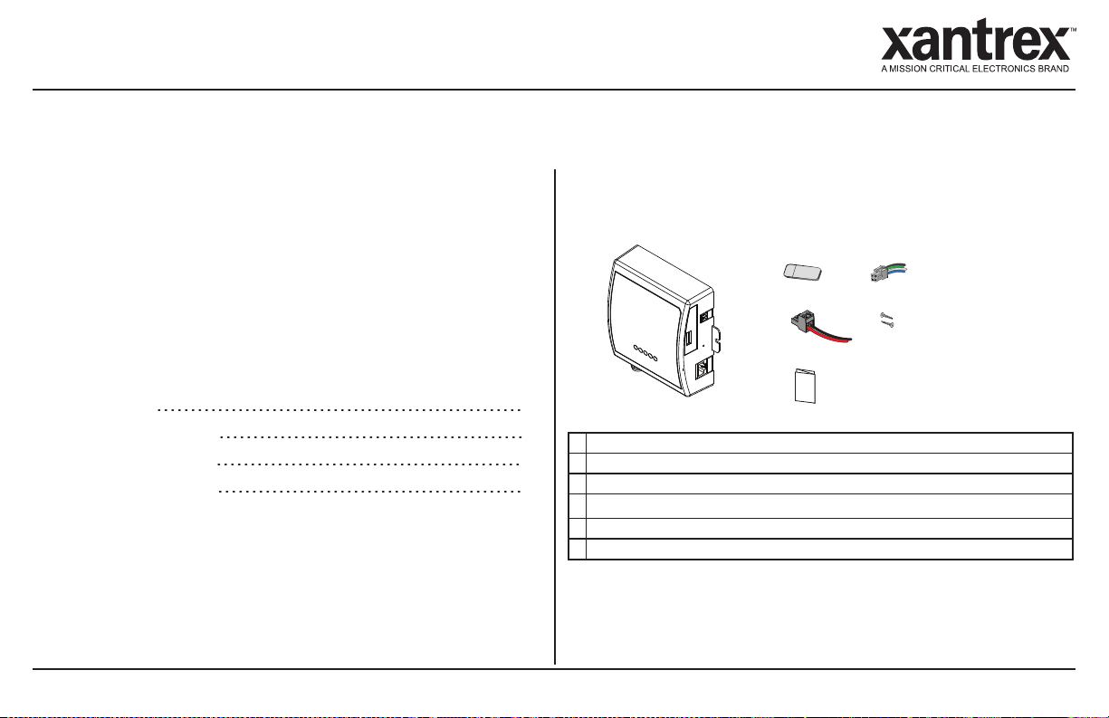
Product Name and Part Number
Xantrex Gateway (808-0888)
Contact Information
Telephone: +1-800-670-0707 (Toll Free USA/Canada) / +1-
408-987-6030 (Outside USA/Canada)
Email: customerservice@xantrex.com
Web: https://xantrex.com/support/get-customer-support/
Information About Your System
As soon as you open your product, record the following
information and be sure to keep your proof of purchase.
Serial Number ____________________________
Product Number ____________________________
Purchased From ____________________________
Purchase Date ____________________________

975-1036-01-01 3
Abbreviations and Acronyms
AC[V]Alternating Current, Mains
CAN Controller Area Network bus protocol
DC[Z]Direct Current
EMC Electromagnetic Compatibility (emissions and immunity)
EMI Electromagnetic Interference source (emissions only)
IP Ingress protection rating (example: IP20 is for Indoor Use only)
kW Kilowatts (1000 watts)
LED Light Emitting Diode
NMEA
NMEA2000
National Marine Electronics Association
NMEA2000 CAN Bus Marine Communications Protocol
PN Product Number
RV-C Recreational Vehicle (Caravan) CAN Bus Communications protocol
SD Secure Digital
SSID Service Set Identifier
V, VAC, VDC
V, VV, VZ
Voltage, Volts AC, Volts DC
Product Safety Information
NOTICE
RISK OF ELECTRIC SHOCK AND EQUIPMENT DAMAGE
nConnect communication circuits only to Safety Power Source
Class 1 (PS1) circuits. This device connects to a 9-65VZ
battery source through the two-pin battery terminal (see
Connection Terminals on page 8).
nDo not expose the Xantrex Gateway to rain, snow, spray, or
bilge water. For indoor use only.
nDo not disassemble. No user serviceable parts inside.
nDo not install and/or operate in compartments containing
flammable materials or in locations that require ignition-
protected equipment.
Failure to follow these instructions may result in injury or
equipment damage.

4 Xantrex Gateway Owner's Guide
EMI/EMC Information
This device complies with part 15 of the FCC Rules and contains a licence-exempt transceiver that complies
with ISED Canada’s licence-exempt RSS Rules. Operation is subject to the following two conditions:
(1) This device may not cause harmful interference, and
(2) this device must accept any interference received, including interference that may cause undesired
operation.
These limits are designed to provide reasonable protection against harmful interference in a residential
environment. This equipment generates, uses, and can radiate radio frequency energy and, if not installed and
used in accordance with the instructions, may cause harmful interference to radio communications.
However, there is no guarantee that interference will not occur in a particular installation. If this equipment does
cause harmful interference to radio or television reception, which can be determined by turning the equipment off
and on, the user is encouraged to try to correct the interference by one or more of the following measures:
-Reorient or relocate the receiving antenna.
-Increase the separation between the equipment and receiver.
-Connect the equipment into an outlet on a circuit different from that to which the receiver is connected.
-Consult the dealer or an experienced radio/TV technician for help.
Contains:
FCC ID: 2ABCB-RPIZ2
IC: 20953-RPIZ2
cCAUTION
Unauthorized changes or modifications to the equipment could void the user’s authority to operate the
equipment.
In addition, this device is in compliance with the CE Marking Radio Equipment Directive for RF spectrum and
RF safety as well as the EMC Directive for emissions and immunity requirements.
End of Life Disposal
The Xantrex Gateway is designed with environmental awareness and sustainability in mind. At the end of its
useful life, the Xantrex Gateway can be decommissioned and disassembled. Components which can be
recycled must be recycled and those that cannot be recycled must be disposed of according to local, regional, or
national environmental regulations including the WEEE Directive.
Many of the electrical components used in the Xantrex Gateway are made of recyclable material like steel,
copper, aluminum, and other alloys. These materials can be auctioned off to traditional scrap metal recycling
companies who resell reusable scraps.
Electronic equipment such as the circuit boards, connectors, and fuses can be broken down and recycled by
specialized recycling companies whose goal is to avoid having these components end up in the landfill.
For more information on disposal, contact Xantrex.

TABLE OF CONTENTS
INTRODUCTION 7
Materials List 7
Connection Terminals 8
Port Pin Assignments 9
LED Status Indicators 9
INSTALLATION 11
Mounting 11
System Installation Diagram 13
Power Source Wiring 14
Freedom Combox Wiring 14
Freedom XC PRO Inverter/Charger Wiring 15
Xantrex Battery Wiring 15
Freedom EX Inverter/Charger Wiring 16
MPPTSolar Charge Controller Wiring 16
CONFIGURATION 17
Xantrex App Connection 17
Wi-Fi Connection 21
Web Application 22
Home Screen (Devices) 26
Settings 26
Control 27
Alerts 27
Xantrex Gateway Settings 28
Xantrex Gateway Software 29
TROUBLESHOOTING 31
Common Issues 32
Maintenance 34
SPECIFICATIONS 35
Physical Specifications 35
Electrical Specifications 36
Compatible Devices 36
Regulatory 37
975-1036-01-01 5

This page is intentionally left blank. [2]

1 INTRODUCTION
The Xantrex Gateway is a single-box communications hub from
Xantrex that is capable of interfacing with a number of Xantrex
inverters, chargers, inverter/chargers, lithium-ion battery BMS,
and solar charge controllers. You can connect your smart phone,
tablet, or a laptop to the Xantrex Gateway in two ways; (1) using
Bluetooth and the Xantrex App or (2) via its Wi-Fi access point
and access its embedded Web Application called
xantrexapp.com, to monitor, control and change settings on any
of the connected devices.
This chapter includes the following topics:
Materials List 7
Connection Terminals 8
Port Pin Assignments 9
LED Status Indicators 9
Materials List
The Xantrex Gateway package includes the following items:
B
E
F
C
D
A
AXantrex Gateway
BmicroSD card reader
CRV-C (CAN port) 4-pin connector with pigtail
Dpower supply 2-pin connector with pigtail, 14–28AWG (0.2–1.5mm2)
E2x mounting screws 6-20½" (or equivalent)
FQuickstart guide
NOTE: If any of the items are missing, contact Xantrex or any
authorized Xantrex dealer for replacement. See Contact
Information on page 2.
975-1036-01-01 7

Connection Terminals
8 Xantrex Gateway Owner's Guide
Connection Terminals
D
F
G H I J
A
B
E
C
ABattery input power supply terminal (connect using the supplied power supply 2-pin connector with pigtail
to a 9-65VZpower source only).
Bmicro-SD card slot for the supplied micro-SD card
cDo not remove the micro-SD card.
CReset button -press to restore the Wi-Fi SSID and password to factory settings.
DRJ-45 RV-C (CAN) port-connect to a compatible RV-C (CAN) device such as a compatible Xantrex
Freedom EX unit, Xantrex Freedom XC PRO unit, or a Xantrex Battery (PN: 884-XXXX-XX only).
cIf the Xantrex Gateway device is the end device of an RV-C (CAN) network, then you must turn on the
CAN terminator switch. Refer to Activate RV-C (CAN Network) Internal Terminator on page 25.
ERJ-45 RS-485 Modbus port-connect to an RS-485 Modbus device such as a Xantrex MPPT Solar
Charge Controller (SCC)
FNMEA 2000 [Micro-C (CAN)] port-connect to an auxiliary NMEA2000compatible device such as a
vessel monitoring system (VMS) or FreedomXCPROMarine.
cRESERVED FOR FUTURE USE.
GRV-C (CAN) bus port-connect to an auxiliary device such as a compatible RV controller, a Xantrex
Freedom EX unit, a Xantrex Freedom XC PRO unit, or a Xantrex Battery (PN: 884-XXXX-XX only).
H5V 0.5A USB host ports
cDO NOT USE. RESERVED FOR FUTURE USE ONLY.
I
J
RJ-12 RS-232 ports
cRESERVED FOR FUTURE USE.

Port Pin Assignments
975-1036-01-01 9
Port Pin Assignments
NOTE: Match port pin assignments to connector pins carefully.
E
GF
H
I
J
A
B
C
K
D
APin1: +12_CAN
Pin2: NC
Pin3: GND
Pin4: CAN1_RV-C_L
Pin5: CAN1_RV-C_H
Pin6: GND
Pin7: +12_CAN
Pin8: GND
RJ-45 port[RV-C (CAN)]
BCAN_L
NMEA 2000 [Micro-C (CAN)] portCCOM
DCAN_H
ECAN_Shield
RV-C (CAN) port
FCOM
GCAN_L
HCAN_H
IBattery neg(–), GND
Battery terminals for power
JBattery pos(+)
KPin1: NC
Pin2: NC
Pin3: RS485-B
Pin4: RS485-B
Pin5: RS485-A
Pin6: RS485-A
Pin7: NGnd
Pin8: NGnd
RJ-45 port[RS-485 (Modbus)]
LED Status Indicators
Power
Status
Wi-Fi
CAN
Modbus
Power Green The Xantrex Gateway is connected to a 9-65VZbattery as its
main power source.
Off The Xantrex Gateway is disconnected from its main power
source.
Status Off cReserved for future use.
Wi-Fi Green The Xantrex Gateway is connected to the Wi-Fi network.
Off No Wi-Fi connection is detected
CAN Green CAN device is detected.
Off No CAN device is detected.
Modbus Green Modbus device is detected.
Off No Modbus device is detected

This page is intentionally left blank. [2]

2 INSTALLATION
Before beginning your installation, read this entire chapter,
assemble all the tools and materials you require, and be aware of
all safety and electrical codes which must be met when installing
as part of a power system.
This chapter includes the following topics:
Mounting 11
System Installation Diagram 13
Power Source Wiring 14
Freedom Combox Wiring 14
Freedom XC PRO Inverter/Charger Wiring 15
Xantrex Battery Wiring 15
Freedom EX Inverter/Charger Wiring 16
MPPTSolar Charge Controller Wiring 16
Mounting
IP20
-4
122
-20
50
ºF ºC
PS1
975-1036-01-01 11

12 Xantrex Gateway Owner's Guide
Consider the following suggestions for mounting.
nLocate the Xantrex Gateway as close as possible to its power
supply.
nThick walls, metallic objects, and other communication devices
may interfere with the signal and affect signal strength. See
Notice below.
nAvoid exposure to direct sunlight.
nBe at least within 20 feet (6 m) to obtain the best possible Wi-Fi
signal from the Xantrex Gateway.
NOTICE
WI-FI INTERFERENCE
Place the Xantrex Gateway away from other Wi-Fi devices such as
a wireless modem (if present) at least 2 feet (0.6 meter) from each
other.
Failure to follow these instructions can produce interference in
communications.
> 2ft. (0.6m)

System Installation Diagram
975-1036-01-01 13
System Installation Diagram
This diagram illustrates a system installation that represents a complete and well-integrated Gateway network for your vehicle or
vessel.
Figure 1 Typical Vehicle Communication Network
cThe solid lines are the communication cables. The dotted lines are electrical power connections. Use the installation guide for each power system device.
100Ah @ 12V

Power Source Wiring
14 Xantrex Gateway Owner's Guide
Power Source Wiring
100Ah @ 12V
A
B
CE
F
G
D
cAttach battery cables to the 2-pin
connector before plugging the connector
to the Xantrex Gateway.
aThe Xantrex Gateway has no power
switch.
AXantrex Gateway E10A fuse/fuseholder
BPower port 2-pin connector (supplied) FBattery disconnect device
acKeep the disconnect device open to
prevent energizing the Xantrex Gateway.
CBattery pos(+) cable GBattery
DBattery neg(–) cable
Freedom Combox Wiring
NOTE: Consult the Freedom Combox Owner's Guide for more information.
cCAN network termination may be
required. See how to activate it using
the web app on page 25.
cOnly one auxiliary device can be
connected at any time. In this diagram, a
universal control monitor is connected
via the RV-C port.
AXantrex Gateway DRV-C (CAN port) 4-pin connector with
pigtail (supplied). Splice the connector to
one end of the patch cable.
B25-ft cable supplied from the optional
Freedom X inverter. Connect to
REMOTEport.
EPatch cable (not supplied)
COptional Freedom X inverter

Freedom XC PRO Inverter/Charger Wiring
975-1036-01-01 15
Freedom XC PRO
Inverter/Charger Wiring
NOTE: Consult the Freedom XC PRO inverter/charger Owner's Guide for electrical connections to batteries,
AC source, and loads.
A
C
D
1
3 4
1
3
4
E
F
B1 12
11
11
12
1
1
11
121
3
4
cCAN network termination may be
required. See how to activate it using
the web app on page 25.
cOnly one auxiliary device can be
connected at any time. In this diagram,
the optional Freedom XC PRO
inverter/charger connects via the RV-C
port.
AXantrex Gateway D20-pin harness (not supplied). Splice the
harness's wires to the patch cable wires.
BRV-C (CAN port) 4-pin connector with
pigtail (supplied). Splice the connector to
the patch cable wires.
EOptional Freedom XC PRO
inverter/charger
CPatch cable (not supplied) FMatch B-C-Dwhen splicing wires.
Xantrex Battery Wiring
NOTE: Consult the Xantrex Battery Owner's Guide for electrical connections.
E
F
DA
B
C
16
12 7
pin 4
pin 5
pin 8
pin 7
cCAN network termination may be
required. See how to activate it using
the web app on page 25.
cOnly one auxiliary device can be
connected at any time. In this diagram, a
Xantrex Battery is connected via the RV-
C port.
AXantrex Gateway DDEUTSCH 12-pin harness (not supplied).
Splice the connector to one end of the patch
cable.
BCAN port RJ-45 connector (not supplied). EXantrex Battery (PN: 884-XXXX-XX series
only)
CPatch cable with RJ-45 connector on one
end (not supplied). Terminate the other end
of patch cable with the appropriate
connector.
FMatch B-C-Dwhen splicing wires.
cConsult the Installation Guides of each of
the connectors.

Freedom EX Inverter/Charger Wiring
16 Xantrex Gateway Owner's Guide
Freedom EX Inverter/Charger
Wiring
NOTE: Consult the Freedom EX inverter Owner's Guide for electrical connections to batteries, AC source,
and loads.
D
A
B
C
E
F
cCAN network termination may be
required. See how to activate it using
the web app on page 25.
cOnly one auxiliary device can be
connected at any time. In this diagram,
the optional Freedom EX
inverter/charger connects via the RJ45
RV-C port. Multiple Freedom EX
inverter/chargers may be connected by
daisy chain and the Xantrex Gateway
will be the terminating device in the
network.
AXantrex Gateway DRJ-45 connector (not supplied).
BCAN port RJ-45 connector (not supplied). EOptional Freedom EX inverter/charger
CPatch cable (not supplied) FNetwork terminator (not supplied)
MPPTSolar Charge Controller
Wiring
NOTE: Consult the Xantrex MPPT Solar Charge Controller Owner's Guide for electrical connections to
batteries, solar panel, and loads.
AB
C
cModbus network 120-ohm
termination may be required.
cOnly one auxiliary device can be
connected at any time. In this diagram,
the optional Xantrex MPPT Solar Charge
Controller connects via the RJ45
Modbus port. Multiple Xantrex MPPT
Solar Charge Controllers may be
connected by daisy chain and the
Xantrex Gateway will be the terminating
device in the network.
AXantrex Gateway COptional Xantrex MPPT Solar Charge
Controller
BPatch cable with Modbus RJ-45 connectors
(not supplied)

3 CONFIGURATION
This chapter explains how to operate the Xantrex Gateway and
configure devices using its web application interface. This
chapter includes the following topics:
Xantrex App Connection 17
Wi-Fi Connection 21
Web Application 22
Home Screen (Devices) 26
Settings 26
Control 27
Alerts 27
Xantrex Gateway Settings 28
Xantrex Gateway Software 29
Xantrex App Connection
Requirements: iPhone/iPad (iOS version 11 or newer), Android
phone/tablet (Android version 7.0 or newer)
How to... Steps
Connect to the Xantrex
Gateway via the Xantrex App.
1.Make sure that the Xantrex Gateway is powered. Observe the Power
LED and be sure it is on.
2.Download the Xantrex App and install it on your smart phone.
3.Tap the Xantrex App, tap Device, then tap the Gateway device.
Xantrex-9800000012345676
Gateway
If a pairing code is requested, enter the last six digits of the serial
number found on the unit.
SN:
98000000123456
six-digit pairing code
975-1036-01-01 17

18 Xantrex Gateway Owner's Guide
How to... Steps
4.Tap Settings, then Xantrex Gateway, then Wi-Fi Network, then select
xantrexapp and tap DONE.
Xantrex Gateway
Xantrex Gateway
Wi-Fi Network
WI-FI NETWORK
Wi-Fi Network Password
ShawOpen
VerizonHotspot
MyOwnWifi
PublicAccess
ATTHotspot
D O N E
How to... Steps
5.Enter the Wi-Fi password and tap Apply. Tap Status and tap Connect to
wlan0 IP Address.
MyOwnWifi
WI-FI NETWORK
Wi-Fi Network Password
MyOwnWifi
*******
Apply Cancel

975-1036-01-01 19
How to... Steps
6.It is recommended to change the default SSID and password. Tap Save.
How to... Steps
Connect to the Xantrex
Gateway via a Xantrex
Gateway hotspot
1. Go to your smart phone's Wi-Fi settings, look for the xantrexapp SSID
and connect to it.
2.Tap the Xantrex App, tap Status, and tap Connect to aplan0 IP Address.
xantrexapp

20 Xantrex Gateway Owner's Guide
How to... Steps
3.Change the default SSID and password, if desired then Tap Save.
xantrexapp-newname
*******
STEP1: SET A NEW GATEWAY SSID AND PASSWORD
How to... Steps
4. Tap Device. If other Xantrex devices are connected it will show up
together with the Xantrex Gateway.
Xantrex-98000000123456
Gateway
Xantrex-8000000123456
Xantrex Battery
Xantrex-000000123456
Freedom EX
Table of contents
Other Xantrex Gateway manuals
Popular Gateway manuals by other brands

wowvision
wowvision proVEOS user manual

Kimberly-Clark PROFESSIONAL
Kimberly-Clark PROFESSIONAL 2AQVA-ONVAHUB51914 quick start guide

Coronis
Coronis WaveCard 25mW user manual

RTA
RTA 460ECMS-NNA1 Product user guide

RTA
RTA 460PSA-N34 Product user guide

TopJet Alert
TopJet Alert Ethernet Gateway quick start guide