Xebex Fitness Air Cycle Quick start guide

Air Cycle

ASSEMBLY PREPARATION
To ensure ease of product assembly, please take time to verify the size and quantities of all required assembly hard-
ware. Use the itemized parts listing and hardware chart for reference.
The product assembly process has been documented in easy to follow steps. Please read all assembly instructions
carefully. Take time to review the manual and familiarize yourself with the entire assembly process before proceeding.
Assembly Tip: It is always helpful to pre-stage the items needed for each assembly step.
Perform product assembly in a 4-ft. x 10-ft. flat area. Note: After assembly is completed, allow a minimal 2-3 feet of
space on each side of rower for user access and dismounting.
Do not dispose of any packaging materials until assembly of the product is completed.
Assembly tools are included, but you may also use standard household tools to complete assembly of this product.
IMPORTANT PRECAUTIONS
WARNING: To reduce the risk of injury, please read the following precautions before assembling or using your new product.
1. It is the responsibility of the owner to ensure that all users of this equipment are adequately informed of stated precautions.
2. Read all instructions and enclosed literature carefully. Understand the assembly and operation before using the equipment.
3. Use equipment on a flat level surface. Use adjustment levelers on the bottom of equipment to help stabilize unit.
4. It’s recommended to place an exercise mat beneath the equipment for added protection of floors or carpets.
5. Keep children and pets away from equipment at all times.
6. Inspect product on a frequent basis. Tighten loose assemblies or hardware as needed. Replace worn or damaged parts.
7. This equipment is intended for indoor use only. Use in non-recommended environment can lead to serious injury and will void all
related warranties and liabilities.
8. Recommended user weight should not exceed the maximum weight limit.
9. Keep equipment clean and properly maintained.
10. Observe and adhere to all warning labels posted on equipment.
11. Properly warm up and stretch before starting any strength training or cardio exercise routine.
12. If you feel pain or dizziness at any time while exercising, stop immediately and consult your physician.
SAFETY WARNING: Before starting an exercise program, consult your physician. This is especially important for individuals over
the age of 35 or persons with pre-existing health problems. It’s important to read all instructions carefully. We assume no responsibil-
ity for personal injury or consequential damages sustained by or through the use of this equipment. Additional terms and conditions are
listed in the back of this manual or enclosed owner’s manual.
Colors and specifications subject to change without notice.
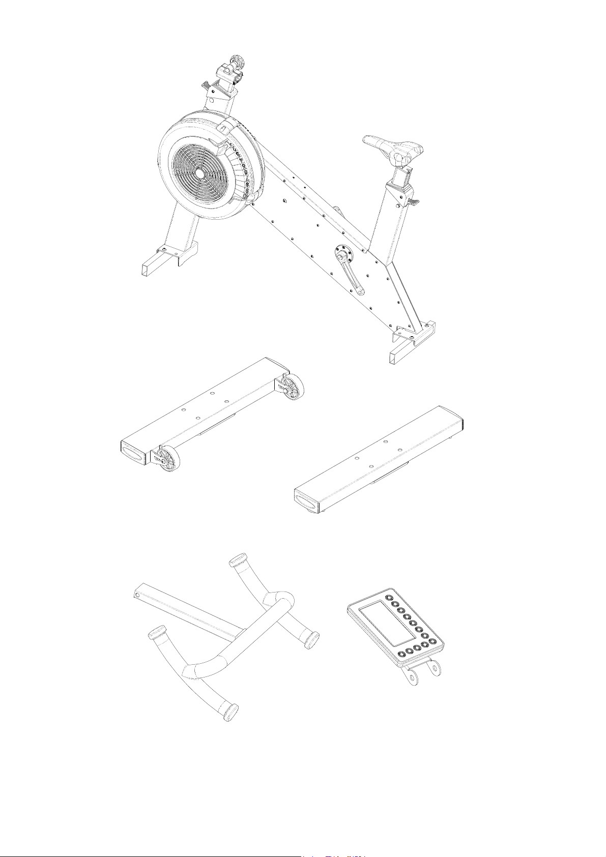
NOTE: Before assembly please lay out ALL pieces accordingly to ensure you
are not missing any items.
PLEASE BE CAUTIOUS as some components may be sharp and can cause
harm if not handled correctly. Always use safety measurements when
assembling any piece of equipment or machinery.

AS-Main Frame Set
E-Handle Bar
DS-Front Stabilizer Set
GS-Console Set
CS-Rear Stabilizer Set

J5-Flat Washer
J6-Flat Washer
J4-Nut J8-Hex Head Screw
J9-Nut Cap J7-Console Pivot Bushing
G2-Right Pedal G1-Left Pedal
J2-Bolt M10 x 55mm
J3-Flat Washer

Use the 6mm Allen wrench to remove 2x Bolts M8x12mm (B1) and disassemble the Packaging
Tube (B) from the Main Frame Set (AS). The Packaging Tube (B) is used for packaging purposes
only and won’t be needed again during/after the assembly.
6MM
Step 1.
Attach the Front Stabilizer Set(DS) & the Rear Stabilizer Set(CS) onto the Main Frame Set(AS)
and secure them with 4x Bolt M10x55mm (J2) and 4x Flat Washer (J3). .
B1
B
AS
Step 2.
CS
J2
DS
J3
AS
6MM

Step 4.
Slightly loosen the Knob (A11) and then insert the Handlebar (E) to the Main Frame Set-(AS).
Secure the Console Set(GS) onto the Handle Bar (E) with 1x Hex Head Screw (J8),
2x Flat Washer (J6), 2x Flat Washer (J5), 1x Nut (J4) and 2x Console Pivot Bushing (J7).
Finally, put on2x Nut Cap (J9). Connect the Console Wire (M4) with console wire in Console Set(GS).
Then, connect the other end of the Console Wire (M4) together with the Generator Wire (M1),
the VR Sensor Wire (M2) and the Resistance Level Wire (M3).Secure the Console Wire (M4) to the
Handle Bar (E) with 1 x Screw (M5).
Attach the Left Pedal (G1) onto the Main Frame Set(AS) by screwing in Counter-Clockwise;
repeat for the Right Pedal (G2) by screwing in Clockwise.
Step 3.
AS
E
J4
GS
J5
J6
J7
J8
J9
A11
M4
M3
M2
M1
M5
G1
G2
AS

Press the Lever (A14) and pull upwards the seat post to desired height.
Step 5.
A14

G3

NO. NAME SPE
PARTS LIST
CIFICATION Q'TY NO. NAME SPECIFICATION Q'TY
AMain Frame 1 E8 Spring Washer M5 4
A1 Retractable Sleeve
2 E9 Screw M5×10mm 4
A2L
Square Inner Sleeve-L
2 E10 Aluminum Sleeve 6
A2R
Square Inner Sleeve-R
2 E11 Magnet Base 1
A3 Double-Head Screw Φ8×65mm 2 E12 Ring Magnet 1
A4 Nut M8 4 E13 Aluminum Plate 3
A5 Round Steel Rod Φ6×50mm 2 E14 Screw M4×25mm 6
A6 Screw M6×8mm 4 E15 Flywheel Shaft 1
A7 Screw M6×10mm 6 E16 Drive Belt Pulley- PJ 1
A8 Spring Washer M6 2 E17 Nut M10 1
A9 Screw M8×80mm 2 E18 Inner Main Cover 1
A10 Nut M8 2 E19 Outer Main Cover 1
A11 Knob M8 2 E20 Plug
Φ17
1
A13 Lever Support Column
Φ10×49.5mm
2 E21 Magnetic Resistance
Level Shield
1
A14 Lever 2 E22 Reed Switch Board
1
A15
Upper Steel Cover
Stainless steel 0.8T 1 E23 Screw M8×16mm 2
A16 Screw M6x6mm 42 E24 Tapping Screw M2×6mm
3
BPackaging Tube 2 E25 Tapping Screw M4×8mm 6
B1 Screw M8x12mm 4 E26 Tapping Screw M4×20mm 4
C Rear Stabilizer 1 E26-1
Tapping Screw M4×10mm 3
C1 Wing Nut M12 2
C2 Knob 2
E27 Damper Disc Cover 1
D Front Stabilizer
1
E28 Plastic Flywheel Fan 1
D1 Transportation Wheel 2
E29 Fan Plate 1
D2 Nut M8 2
E30 Mesh 1
D3 Screw M8×50mm 2
F Saddle Post 1
D4 Tapping Screw M4×12mm 4
F1
Adjuster Plate
2
D5 Square Pad 2
F2 Screw M6×12mm 4
D6 Tube End Cap 40×100 4
F3 Screw M6×8mm
2
F3-1 Spring Washer M6 1
E1
Screw
M4 8
F4 Saddle Set 1
E2
Clip
S20 1
F5 Saddle 1
E3 Steel Washer 1
F7 Handle Bar Post 1
E4 One-Way Bearing FC2016 1
F8L
Handle Bar Post Sleeve-L
2
E5
Flywheel Bearing Holder
1
F8R
Handle Bar Post Sleeve-R
2
E6 Bearing 6004 2
G Console 1
E7 Clip R42 2
G3 Console Base 1
E
Handle Bar Assembly
1

NO. NAME SPECIFICATION Q'TY NO. NAME SPECIFICATION Q'TY
H Magnet Base
1
K15 Flat Washer
2
H1 Screw 1
K16 Flat Washer
4
H2 Spring Washer M8 2
K17 Bearing
6300 4
H3 Nut
M8
2
K18 Drive Belt Disc-PJ
Φ180
1
H4 Screw 1
K19
Drive Belt Pulley-PJ
1
H5 Screw
1
K20
Bolt M8×16mm
2
H6 Powder metallurgy 1
K21 Clip
S15
2
H7 Magnet
Φ5×3T
Φ10×2T×Φ20
Φ10×1T×Φ20
Φ10×2T×Φ18
1
K22 Screw
M8×12mm
M6×10mm
4
H8 Magnet Control Bar 1
K23 Bearing 6002
2
H9
Magnet Control Rod
Φ5×44mm
1
K24
Flywheel Bearing Sleeve
Φ15×50mm
1
H10
Magnet Control Shaft
1
K25 Bearing Holder 2
H11
Spring 1
K26
Bolt
12
H12
Nut M5 1
K27
Bearing
6204
2
J2 Bolt
M10×55mm
M5×10mm
M8×40mm
M4×8mm
8
8
K28
Clip
R40
2
J3
Screw
M4×6mm
1
K29 Spacer 2
J4 Nut 1/2"-13UNC 1
K30 Bearing 6903
1
J5 Flat Washer
Flat Washer
1/2"×1T×Φ32 2
K31 6903 Rubber Ring
1
J6 Flat Washer 1/2"×2T×Φ23 2
K30-1
Bearing
6001
1
J7 Console Pivot Bushing
Left Pedal
Right Pedal
2
K31-1
6001 Rubber Ring 1
J8
G1
G2
Hex Head Screw
1/2"×3 1/4" 1
K32 Bolt M6×12mm
6
K33 Nut M3
2
K34 Screw M3×15mm
2
K1L
Left Crank
1
K35 Electromagnet
1
K1R
Right Crank
Drive Belt Disc- PK
1
1
2
1
K36 Electromagnet Base
1
Screw
2
K
Φ180
1
K37 Spring Rod Φ6×56mm
2
K3 Nut
Nut Cap
2
K38 Spring
2
K4 Shaft Cap
2
K39 Iron Side Cover-L
1
K5
Screw
M8×16mm
4 K40 Iron Side Cover-R
1
K6 Spring Washer
M8 8
K41
M1
M2
M3
M4
M5
J9
J11
Bottle Holder (Optional) 1
J10
Round Cap
Generator Wire
VR sensor wire
Resistance Level Wire
Console Wire
1
1
1
1
1
K7 Shaft
1
K8 Nut
M20
2
K9 Drive Belt
1095PK6 1
K10
Drive Belt
430J6
1
K11
Idler Pulley Bracket
2
K14 Clip S10 2
Idler Pulley Shaft
Idler Pulley Sleeve
K12 Φ10×30mm 2
K13
Φ10×50mm
2
PARTS LIST
Table of contents
Other Xebex Fitness Exercise Bike manuals
Popular Exercise Bike manuals by other brands

Interactive Fitness
Interactive Fitness Expresso S3 Assembly and installation guide

Everlast
Everlast ULTRA EX BIKE Assembly & user instructions

Star Trac
Star Trac eSPINNER Installation and operation manual

Life Fitness
Life Fitness LC-5500 owner's manual

Pro-Form
Pro-Form 450 Ur Bike manual

Bodyworx
Bodyworx ABW300 owner's manual