Xeltek SUPERPOR/6100N User manual

1
Important Information:
1. This manual applies to SUPERPOR/6100N, SUPERPOR/611S, SUPERPOR/610P.
2. In order to connect the programmer easily and quickly, please connect the
hardware after installing the software.
3. Please read this manual carefully before using programmers.
4. Please do not use self-made adapters. It is recommended to buy the adapter made
by Xeltek.
Copyright Notice
Software Copyright 2012-2022 XELTEK
User's Guide Copyright 2012-2022 XELTEK
The distribution and sales of the product are intended for use by the original
purchaser under the terms of the License Agreement.
This document may not, in whole or part, be copied, photocopied, reproduced,
translated or reduced to any electronic medium of machine-readable form without
prior consent in writing from XELTEK.
The information in this document is subject to change without notice.
In the event of any discrepancy in respect of meaning between the software and
the manual due to the upgrade of the software version, the software shall prevail.
SUPERPRO®is the registered trademark of XELTEK.

2
Chapter 1 General Description
1.1 INTRODUCTION
1.1.1 What is SUPERPRO?
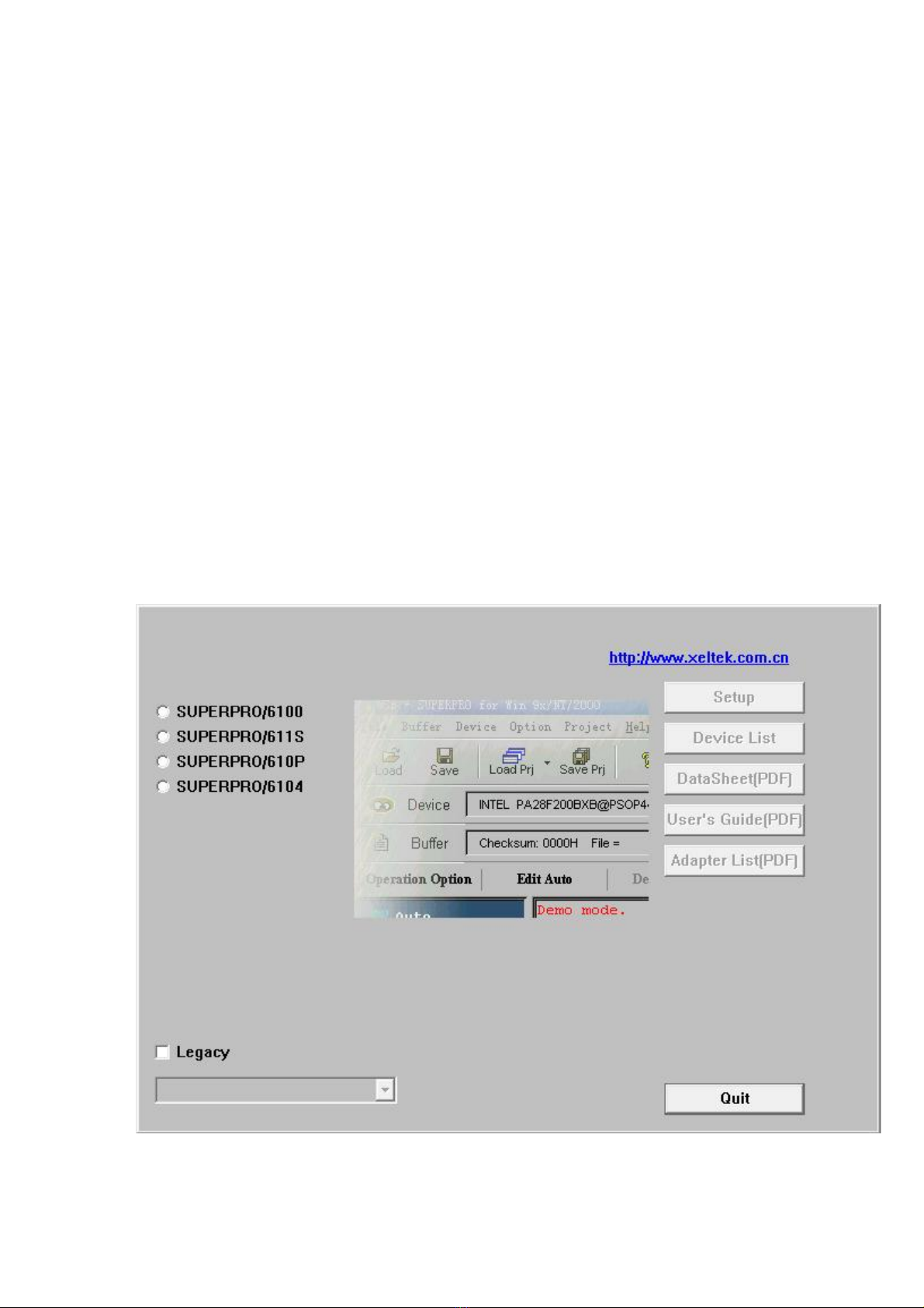
The SUPERPRO is a series of cost-effective, reliable, and high-speed universal
programmers. They are designed to communicate through a USB 2.0 port and to
operate with most IBM-compatible desktop computers and notebook computers based
on Pentium. Their menu-driven software interface facilitates the operation.
Programming hardware includes the following items:
A programming module
A power supply unit
A USB connection cable
Optional socket adapters with 144 pins universal pin-drivers design to
support devices with 144 pins or less and accommodate PLCC, TSOP, SOIC,
SOP, QFP, TSSOP and BGA package types are available
Software features (USB 2.0 Series):
Support Windows XP , Windows Vista, Win 7/8.
Support numerous (over 10,000) types of devices, including PROM,
E/EPROM, PLD and MCU from more than 150 manufacturers.
Support many types of formats such as Binary, Intel (linear & segmented)
Hex, Motorola S, Tektronix (linear & segmented), JEDEC, POF, etc.
Device insertion test (48 pins or less) to detect defective chips, improperly
inserted devices and pins of poor contact (model dependent)
Integrated full screen buffer editing environment with commands such as fill,
copy, move, swap, etc.
Auto-generation of electronic serial numbers. (Only authorized users can use
the user-defined methods).

3
1.1.2 Manual Organization
This manual consists of three parts:
Part 1: Introduction to the SUPERPRO series, including system requirements,
software and hardware installation.
Part 2: Detail explanations on the software commands and all the function items.
Part 3: Appendix, including customer support information and error messages.
1.1.3 System Requirements
The minimum system configuration is as follows:
Desktop or laptop, with Intel Pentium or equivalent processor, has at least one
standard (USB2.0) compliant connector.
Windows XP/Vista operating system.
One CD-ROM drive.
A hard disk with at least 1 GB free space
1.1.4 Programmer Package
The standard package contains the following items:
One programmer module.
One USB connection cable.
One power supply unit.
One software installation CD.
The User's Guide.
A registration form.

4
Chapter 2 System Installation
If it's your first time to use the USB-based programmer of XELTEK, this chapter will
help you to install the software and connect the programmer hardware properly. USB
devices are PnP devices. At the first installation, Windows will start with "new
hardware wizard" to scan all available INF files, and find out the appropriate drivers
for the newly found hardware. In order to avoid unwanted complication during the
installation of USB device, we strongly suggest that you install the software first. The
setup program will handle the needed INF files and drivers automatically.
2.1 Software Setup
2.1.1 Setup from the CD-ROM
Insert the CD into the CD-ROM drive.
If the setup program starts automatically, a dialog box will show up for you to select
the programmer model. If the setup program does not start automatically, please run
SETUP.EXE in the root directory.

5
Select the corresponding model of the programmer you have bought. Click Setup to
install the application software for the programmer.
NOTE: Each model has its own software. Please do not mismatch them.
2.1.2 Download the installation software from the Internet
You can download the specific software for a certain model at Xeltek website:
http://www.xeltek.com.cn/. It is usually a self-extracting file. You only need to run
this file to setup the software.
2.1.3 Setup Process
The setup procedure goes step by step and you can change the default settings
according to your needs in the setup process.
Step 1: Select the language that yon want to use in the setup process, as shown in the
following language selection interface.
Click the “OK” button and a dialog box of “Preparing to install” appears.

6
Then a welcome screen appears as shown below.

7
Step 2: Click the "Next" button. The License Agreement appears.
Step 3: Please read the license agreement carefully and click “I Agree” to continue
the installation. Otherwise, click Cancel to exit the installation.

8
Step 4: You can select the installation path in this step. Click the “Browse” button to
change the default destination folder. Click the “Next >” button to continue the
installation.

9
Step 5:
You are asked whether to create a start menu icon and a desktop icon in this step. If
you select the default setting, click the “Next” button to continue.

10
Step 6:
Check the above settings that you set in the setup process. Click the “Install” button
to proceed to the next step.

11
Step 7:
In this step, the files are being copied, the drivers are installed, the software is
registered, etc.
If the user’s operating system is Windows Vista, the following dialog box will appear
on the screen:

12
Now please select “Always install the driver software (I)”. Then wait until the next
dialog box appears.
Step 8:
Click the “Finish” button to finish the setup.

13
2.1.4 The hardware and driver installation
Connect the programmer module to your computer through the USB port. Turn on the
programmer power switch.
After the application software is installed, the driver installation for the first time
connection between the computer and the programmer module becomes very simple.
You only need to wait until new hardware wizard finishes the installation. The
following interfaces will appear on the screen one after another:
The actual interfaces may be somewhat different from the above ones. Anyway the
user should wait until the installation finishes. Please don't run any other programs
during the installation
2.1.5 Running the application software for the programmer
The application software for the programmer has a standard Windows UI, including
pull down menus and buttons, etc. The user should have some knowledge about the
MS Windows OS and be able to use the computer mouse well.
After the application software for the programmer is started, it will communicate with
the programmer immediately and start the initialization. If the communication fails,
please check according to the following steps:
One programmer module. Check the connection between the programmer
hardware and the computer, and turn on the power switch.
Follow the correct installation steps. If the programmer hardware is connected
to the computer before the programmer application software is installed, the
computer will detect the new hardware and the following window will appear.

14
Please click the “Cancel” button lest the OS should install the driver with a
compatible ID and cause some problems.
Chapter 3 Quick Guide
This chapter will help you understand the whole operation process of the chip
programming. The content includes:
Before you start to program any devices, make sure that you have correctly install the
programmer and the computer has succeeded in communicating with the
programmer.
3.1 Description of the User Interfaces
The following interface will appear after the application software for the programmer
is started.

15
1. Main Menu 2. Toolbar 3. Device Selection
4. Data Buffer for Editing 5. Device Messages 6. File Message
7. Operation Option Toolbar 8. Function Items for Operations on Devices
9. Operation Message Window 10. Progress Indicator 11. Statistical Window
Hotkey: SPACE = “Auto”
3.2 The steps of the programming
3.2.1 Hardware Preparation
Before using the programmer to program some device, please make sure the
programmer is installed properly, and communication is established successfully
between PC and programmer.
Some SMD devices need adapters. Please make sure that they are available for the
devices. Insert the chip correctly (Device information for SMD and non-standard
insertion will appear on the screen when the device is selected, if device information

16
does not appears, check if chip insertion orientation follows the guideline of the
standard chip insertion markings near the pin-driver socket).
3.2.2 Select the device
Click the "Device Selection" button or click the "Device" from the main menu and
select the device. The “Device Selection” window will appear. First select the Device
Type (such as E/EPROM, BPROM, SRAM, PLD, or MCU), then select the
Manufacturer and Device Name in the window. Click OK button or double-click the
device to confirm your selection. You can also enter the device part name in the
“Search” box so that the selection is narrowed and can be done quickly.
3.2.3 Load data into Buffer
The process of programming a chip is the process in which the buffer data are written
into the storage units of the chip according to the requirements of the manufacturer.
Data can be loaded into the buffer in the following two ways:
1) By reading data from a file
You may load a file into the buffer by clicking “File” in the main menu and selecting
‘Load File’. The dialog box for loading a file appears after the ‘Load File’ is selected.
In the dialog box, select the folder and file name you wish to load. Then select the
appropriate file type in the ‘File Type’ dialog box appearing subsequently. After
confirmation, the selected data will be loaded into the memory buffer. Please go to
the Buffer edit window and check if the data is loaded correctly.
Note: Some Hex or S record files contain non-zero file start address. In this case, the
start address should be entered in the File Address box.
2) Reading data from master chip:
Insert the master chip in the socket and make the selection of the device to read from.
In the screen of “Function items for operations on the devices”, click Read to copy
the data from the master chip into the memory buffer. At this point, you may go to the
memory buffer edit screen and check if the data is loaded correctly. The data may be
saved to a disk for later use.
Note: Some devices have no read function or are encrypted, under this condition data
cannot be read from.

17
3.2.4 Set Options
1) Operation Option, including:
Insertion Test option. Checking the pin contact before programming.
Device ID Check option. Checking the device’s ID before programming.
Beeper option. Checking whether the beeper sounds on or off when the
operation succeeds or fails.
Auto Increment Function option. If it is enabled, the label number increases
automatically while programming and it is written to a designated place so
that each chip has a different label number.
Address Change option. Changing the start address and end address of
programming zone of the device.
Verification Mode option. Selecting a specific VCC voltage according to the
device requirements in order to ensure that the chip is programmed correctly.
2) Edit Auto. In the window of “Function Items for Operations on the devices”, each
device has a basic batch-processing Auto operation, which automatically executes all
the other operations of the device one after another in a preset order. Normally the
following auto chip programming methods are selected:
Erase
Blank_check
Program
Verify
Security or Protect
3) Dev.Config. For the chip that has the configuration word, the configuration word
must be properly set before programming to ensure that the chip can be used on the
target system. The configuration words for some devices are contained in the data file.
The configuration words are automatically loaded into the configuration word buffer
when the data file is loaded. For some devices, the selection must be made manually.
4) Dev. Information. After a device is selected, the dialog box of the device pops up
and the vital information about the device is displayed in the box. Some devices must
meet some special requirements while programming or there are some special
conventions about the device algorithms. Therefore, the users must adjust operation
steps or buffer data after carefully reading the text in the Dev. Information box. When
an adapter is needed for programming the device, the adapter information will also be
shown.
5) Production Mode. In order to program chips under production mode, the
programmer always conducts the chip insertion test. Once the chip is inserted
correctly, the auto batch-processing command is automatically started and the users
do not need to use keyboard and mouse repeatedly.

18
3.2.5 Programming, writing the Data in Memory Buffer into a Chip
If the chip package is not DIP encapsulation, user may need to buy the adapter
according to the device information and insert the chip properly into the socket..
(Contact Xeltek for selection and purchase of the adapters.)
The operation steps for programming a chip are as follows:
Blank Check. This step can be skipped if the chip is brand new.
Program.
Verify. This step is necessary. The programming cannot be implemented
unless the chip passes the Verification. Some chips do not provide the
unit-to-unit check function, but only provide the accumulation check function,
such as Verify CRC, etc. Some chips even do not provide the accumulation
check function.
For the electrically erasable chips containing some information, the blank
check will fail. In this case, the Erase operation should be performed first
before the blank check. For some EPROM chips, the data can be overwritten.
So no Erase operation needed.
If encryption is required, add Security or Protect function after Verify.
Note: For some devices, the configuration word should be set before the encryption is
carried out. Refer to the detailed explanations on the function.
User can choose Auto to finish all the operations in one step.
3.2.6 Security and Password Input
To prevent the user’s data from being used by others, sometimes the programmer asks
the user to input the password in the operation process.
Set the password: Input a new password.
1. Enter the new password 2. Enter the password for confirmation
If the input password in 1 is the same and the same as in 2, the password is valid. If
there is no input in 1 and 2, it means that no password is needed here.
Note: Spaces are characters and they can be used in the password.
Verify the password: When the data protected with some password are

19
operated on, the password needs to be input.
The description above is necessary for programming a chip. If it is the first time to for
you use the programmer, please refer to “Detail Explanations on the Functions” in
Chapter 4 for more detailed information.
3.3 Muti-programming
This function is only provided by SUPERPRO/6100,SUPERPRO/611S. SUPERPRO/610P
doesn’t support this function (Take SP6100 for example).
SP6100 can be connected to hub, You can connect four SP6100s or one SP6104 by
hub.
Find muti_p.exe at the folder “bin” in the directory where your SP6100’s software is installed.
Run it then following interface shows up.

20
“muti_p.exe” can manage four modules(4 SP6100s or 1 SP6104)integratively. The main screen
is a management interface that controls the hardware of the programmer by sending commands to
the SP6100 software. After the main interface, the process of communicating with the SP6100
software starts automatically.
If the system does not find the programmer or something is wrong with a module, select
DisConnect to cancel the connection. Then check the connection between the hardware and
computer. Select Connect to reconnect.
“muti_p.exe” has administrator mode and producer mode. In administrator mode, users can set
projects and save them, then entering producer mode, users can load these project. In producer
mode, users can load different project for different module or load the same project for all the
modules. It’s very convenient and flexible.
NOTE: the hub used to connect SP6100s should be specified by XELTEK.
This manual suits for next models
2
Table of contents
Other Xeltek Motherboard manuals