Xeltek Superpro SB02 User manual

1
Info Content
Superpro
SB0X User Manual
Rev. 03 User Manual
手册信息
Keywords Vision, SB02&05&05X&05E&05EX, V8,SP7500
Abstract This document describes the programming system from XELTEK

SB-02&05
User Manual
XELTEK Automatics
SB0X
XELTEK. 2019. All rights reserved.
User Manual
Rev. 03 - 5th MAY 2020
2 of 200
编辑日志
01
2018-11-27
Initial Edit 04.1
02
2019-05-01
Second Edit 04.2
03
2020-05-21
Third Edit 04.3
More information
Welcome to visit our website: http://www.xeltek-cn.com
Emails for more information : Sales02@xeltek-cn.com

SB-02&05
User Manual
XELTEK Automatics
SB0X
XELTEK. 2019. All rights reserved.
User Manual
Rev. 03 - 5th MAY 2020
3 of 200
Contents
1. System introduction..............................................................................................................................4
1.1. About this manual ....................................................................................................................4
2. System Operations.............................................................................................................................4
2.1. Installation................................................................................................................................4
2.2. Steps of power on/off...............................................................................................................4
2.3. Introduction for the applications................................................................................................4
2.4. Quick Start...............................................................................................................................5
3. Application Instruction.........................................................................................................................6
3.1. SP7500 introduction.................................................................................................................6
3.2. New Specifications of SB0X.....................................................................................................6
3.2.1. Automatically nozzle heights compensation...................................................................6
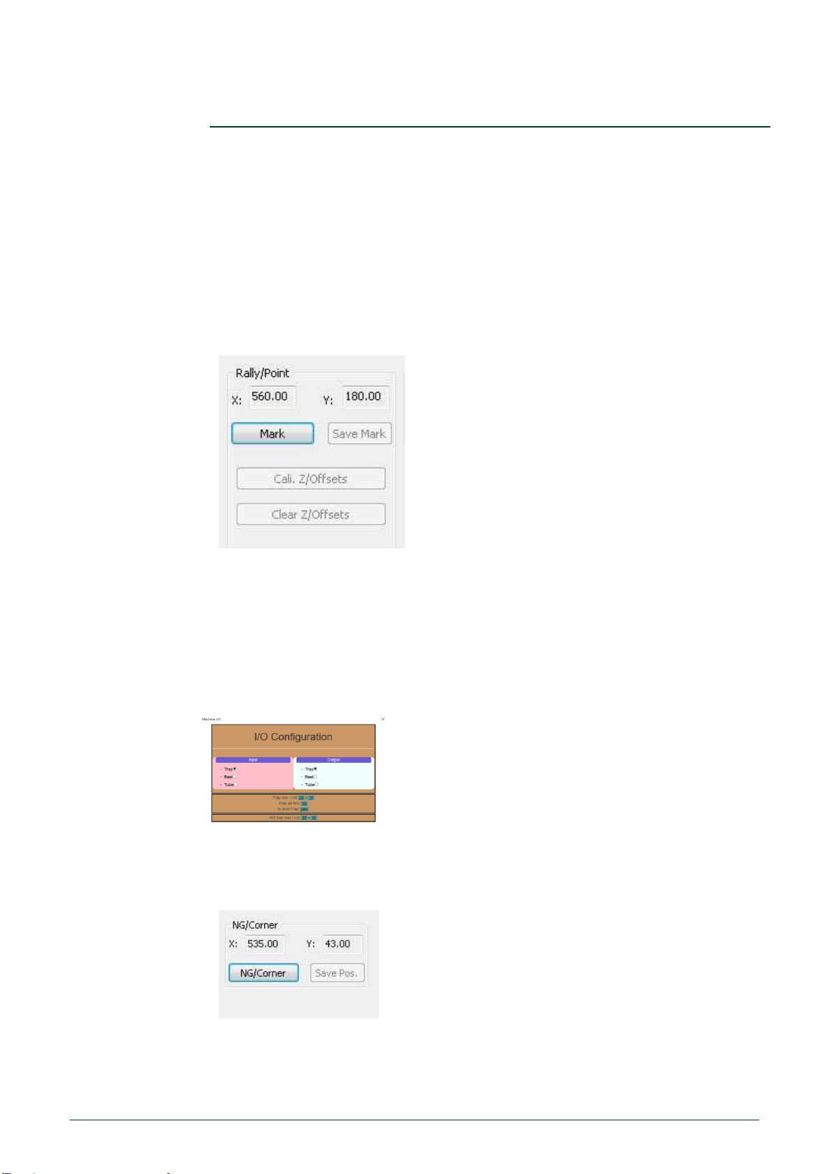
3.2.2. Added NG tray function .................................................................................................6
3.2.3. Added the position setting of the NG corner ..................................................................6
3.2.4. Added instant pause, status retention, and recovery features........................................7
3.2.5. New information display interface, real-time display of UPH and work order status.......7
3.3. SB0X Specifications.................................................................................................................7
3.3.1. Tool Bars.......................................................................................................................7
3.3.2. I/O settings....................................................................................................................7
3.3.3. Configuration settings....................................................................................................8
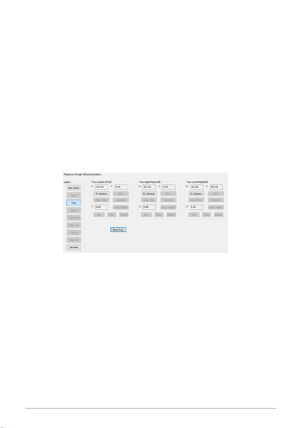
3.3.4. Positioning settings........................................................................................................8
3.3.5. Camera and Vision Check...........................................................................................11
3.3.6. Automatic programming...............................................................................................12
3.3.7. Reports........................................................................................................................12
3.3.8. Connect.......................................................................................................................12
4. Introduction of the mechanical system..............................................................................................13
4.1. System composition...............................................................................................................13
4.1.1. Total power supply and load switch.............................................................................13
4.1.2. Device switch button and emergency stop button........................................................13
4.1.3. Warning lights..............................................................................................................13
4.1.4. Security Door...............................................................................................................14
4.1.5. Control Circuit..............................................................................................................14
4.1.6. Programmers...............................................................................................................14
4.2. System Specification..............................................................................................................14
4.2.1. Motion parameters.......................................................................................................14
4.2.2. Visual parameters........................................................................................................15
4.2.3. Input and output components......................................................................................15
4.2.4. Power supply...............................................................................................................15
4.2.5. Air pressure.................................................................................................................15
5. Maintenance.....................................................................................................................................16
5.1. Daily Maintenance..................................................................................................................16
5.2. Regular Maintenance.............................................................................................................16
6. Trouble shooting...............................................................................................................................17
7. Appendix ..........................................................................................................................................18

SB-02&05
User Manual
XELTEK Automatics
SB0X
XELTEK. 2019. All rights reserved.
User Manual
Rev. 03 - 5th MAY 2020
4 of 200
1. System introduction
1.1. About this manual
This manual applies to SB02 & SB05 & SB05E & SB05X & SB05EX programming
systems.In addition to special instructions, this document is fully applicable to all the
systems.
1.2. Model comparison
2. System Operations
2.1. Installation
Please set the machine to a horizontal location and suspend the rolling wheel with a
height adjustment device.
The power plug should be connected to the I/F cable, please secure it in place.
2.2. Steps of power on/off
Power on:Visually check that the machine is in normal condition and turn on the
switch to on state;
Waiting for the industrial computer ready;
Press the control buttons on the front panel, respectively, for the
system button and programmer control button;
Open the application SB0X and SP7500 to enter debugging or working
status.
Power off:End the session and move the mechanic arms to the home point,then
Turn off the applications ,the industrial PC,the control button in turn.
2.3. Introduction for the applications
SB0xprogramming system consists of two parts ,the mechanic application SB0X and
the programming software SP7500.
SB02
SB05
SB05X
SB05E
SB05EX
Model
SP7500
SP7500
SP108X
SP7500
SP108X
Maximum
programmer
4
8
6
4
4
Maximum
sockets
16
32
48
16
32
Nozzles
1
4
4
2
2
I/O
tape&tube&tray
tape&tube&tray
tape&tube&tray
tape&tube&tray
tape&tube&tray

SB-02&05
User Manual
XELTEK Automatics
SB0X
XELTEK. 2019. All rights reserved.
User Manual
Rev. 03 - 5th MAY 2020
5 of 200
2.4. Quick Start
Step 1:Open the SP7500,load an exist project.
Step2:Open SB0X,click on ,connect the SB0X and SP7500.
Step3:Edit the IO,set the input and out of components,tray and tape are available.
Step4:Go to configuration setting ,set the orientations if need.
Step5:Go to positioning setting ,set the positions and heights of the sockets or
IIO cells.
Step6;Go to automatic sessions, start.
Tips:All the settings will be auto saved according to the adapters.

SB-02&05
User Manual
XELTEK Automatics
SB0X
XELTEK. 2019. All rights reserved.
User Manual
Rev. 03 - 5th MAY 2020
6 of 200
3. Application Instruction
3.1. SP7500 introduction
The application SP7500 in SB0X are same to the single SP7500 programmers.
The project files can be shared from each other.
More details please reference to SP7500 user manual.
3.2. New Specifications of SB0X
3.2.1. Automatically nozzle heights compensation
This function is suitable for multiple nozzle programming system (such as SB05);
Set the MARK point, test the height of four suction nozzles with one click, and the
corresponding compensation value will be calculated automatically;
In the normal programming process, the system will use the compensation value to
improve the height consistency of the pickup plate of each suction nozzle.
3.2.2. Added NG tray function
The system can take the tray as the NG tray when the I/O of the chips are all tapes.
3.2.3. Added the position setting of the NG corner

SB-02&05
User Manual
XELTEK Automatics
SB0X
XELTEK. 2019. All rights reserved.
User Manual
Rev. 03 - 5th MAY 2020
7 of 200
3.2.4. The second tray is added.
This tray can be used to collect NG chips or provide chips programmed in advance.
3.2.5. Added instant pause, status retention, and recovery features
The system will be able to stop or recovery at all situation immediately.
3.2.6. New information display interface, real-time display of UPH and work order status
3.3. SB0X Specifications
3.3.1. Tool Bars
From left to right ,the icons are:
Welcome-Start up interface, showing I/O configuration
Settings-Setting interface
Positioning-Positioning interface
Automatic-Automatic programming interface
Reports-Reports of sessions
Connect-connect the SB0X and the SP7500
Home-Back to the original point
3.3.2. I/O settings
Input and output settings can be selected in this part.
NG tray function has been added to this version !

SB-02&05
User Manual
XELTEK Automatics
SB0X
XELTEK. 2019. All rights reserved.
User Manual
Rev. 03 - 5th MAY 2020
8 of 200
3.3.3. Configuration settings
I/O Orientation:0,90,180.
Height:compensation for the picking or placing height.
Multiple nozzles:two or four nozzles can be selected,the machine will pick two or four
chips at a time.
Correction :the system will do the correction when chips were found not placed well.
3.3.4. Positioning settings
Initial Point
Fixed Camera -
Activate the camera below the countertop.
This function is used to adjust the actual target point of initial point.
Move the cross of the target to the center of the camera.
After setting the target point, the next is reference point.

SB-02&05
User Manual
XELTEK Automatics
SB0X
XELTEK. 2019. All rights reserved.
User Manual
Rev. 03 - 5th MAY 2020
9 of 200
Ref. Point
Activate the camera at the top side.
Adjust the camera to meet the target point.
After the setting of the reference point,please take out the target tool.
Nozzles position
Nozzle - Activate#nozzle
Save - Save the potion of the nozzle,and initial the U Axis to 0.
Auto Pos. - use the template to assist us to set the potions
Position of Programmers
Adjust the positions of the sockets
oCamera - Activate the socket part
▪Move the camera to the center of sockets and take an template for the function of
auto-position.
oSave - Use the coordinates of the current XY axis as the XY coordinates of the cell.
oAuto Pos. - Automatically set XY coordinates using the socket templates
oCamera(2)(Pick&Move) - Pick up the chip to the fixed camera and make a template.
▪Using the fixed camera to make a template for vision check.
oAutoHeight - Test the height for the unit.
▪Please make sure that there’s a chip in the sockets.
▪Please make sure that the air pressure sensor in right setting.
oPick - Pick up the chip in the socket.
oPlace - Place the chip back to the socket.
All modules Auto. Pos.
oAutomatically adjust the sockets’positions by vision system.
oThe current location of the sockets should not be too large for the corresponding
position configuration deviation, which cannot exceed the deviation range allowed by
the machine vision.
oMinor adjustments can only be made within the range of machine vision deviations.

SB-02&05
User Manual
XELTEK Automatics
SB0X
XELTEK. 2019. All rights reserved.
User Manual
Rev. 03 - 5th MAY 2020
10 of 200
Module Auto.Pos
oUse machine vision system for automatic position adjustment.
oThe current location of the sockets should not be too large for the corresponding
position configuration deviation, which cannot exceed the deviation range allowed by
the machine vision.
oMinor adjustments can only be made within the range of machine vision deviations.
Clamp control (Applies only to superpro/sb05)
oClamp_[XX] - XX:Corresponding Programmer flags/locations
oState
▪Red- Closed
▪Green - Open
oOn - Open
oOff - Close
Positions of input/output
Tray - Activate the tray position adjustment interface
oClick on the camera to activate the corresponding cell/slot.
Position adjustment of the input
oCamera - activate the corresponding cell/slot
oSave - Use the coordinates of the current XY axis as the XY coordinates of the cell
oAuto Pos. - N/A
oCamera(2)(Pick&Move) - N/A
oAutoHeight - Test the height for the unit.
▪Please make sure that there’s a chip in the sockets.
▪Please make sure that the air pressure sensor in right setting.
oPick - Pick up the chip in the cell.
oPlace - Place the chip back to the cell.

SB-02&05
User Manual
XELTEK Automatics
SB0X
XELTEK. 2019. All rights reserved.
User Manual
Rev. 03 - 5th MAY 2020
11 of 200
3.3.5. Camera and Vision Check
SB0X systems possess two camera for positioning and vision check respectively.
oAn example for taking a template
This is not a good
template
This is a good
template
oTaking the template for the socket positioning
Try to cover the whole socket;
We can use the calculate button to check the differences between from the picture
and the template.
The deviation will be showed in the next X\Y\A bar.

SB-02&05
User Manual
XELTEK Automatics
SB0X
XELTEK. 2019. All rights reserved.
User Manual
Rev. 03 - 5th MAY 2020
12 of 200
3.3.6. Automatic programming
Start
oStart the programming session
Pause
oOnly when the pause [paused] prompt to enter the pause state.
oThe machine will stop right after the current movement.
oThe button would be disable if the clear up process is under way.
Clear up
oAll the sockets will be cleared
Reset
oReset the status of the programmers
Vision check
oOn - Enable
Device check
oOn - Enable
3.3.7. Reports
Programming information
3.3.8. Connect
Connect to SP7500

SB-02&05
User Manual
XELTEK Automatics
SB0X
XELTEK. 2019. All rights reserved.
User Manual
Rev. 03 - 5th MAY 2020
13 of 200
4. Introduction of the mechanical system
4.1. System composition
4.1.1. Total power supply and load switch
The red knob above is the load switch, after opening the system on the whole machine
power, the industrial computer automatically start.
4.1.2. Device switch button and emergency stop button
Programmer:Button controls the power supply of the programmers.
System:Button controls the power supply of the motors.
Emergency Stop:Emergency button.
4.1.3. Warning lights
Lights:The middle orange light is lit when the machine is preparing;
The green light is lit when the system is running;
The red light is lit when it met an error or stop,

SB-02&05
User Manual
XELTEK Automatics
SB0X
XELTEK. 2019. All rights reserved.
User Manual
Rev. 03 - 5th MAY 2020
14 of 200
4.1.4. Security Door
Security door rule: When the system is running, the security door must be turned off.
Once the security door is turned on, the system will stop immediately.
4.1.5. Control Circuit
4.1.6. Programmers
On the left is the SB05 applicable programmer group, divided into two groups before and
after, a total of 8 modules, through the 8usb line alone communication.
On the right is the programmer group for SB02, and the 4 module is centralized to 1 USB
cable communications via the hub board.
4.2. System Specification
4.2.1. Motion parameters
Maximum machine efficiency: up to 2500UPH.
Composition: High performance Motion Control Board + servo system + screw and guide
rail.
Accuracy: X-axis: ±0.02Mm;y axis: ±0.02Mm;z axis: ±0.02mm.
Effective Stroke: X-axis: 1000Mm;y axis: 500Mm;z axis: 40mm.
Nozzle accuracy:±0.07mm.

SB-02&05
User Manual
XELTEK Automatics
SB0X
XELTEK. 2019. All rights reserved.
User Manual
Rev. 03 - 5th MAY 2020
15 of 200
4.2.2. Visual parameters
Camera: 512x512 pixels.
Visual Range: 30mmx30mm
Visual system adjustment accuracy: x= y=0.07 mm, θ=0.1°
4.2.3. Input and output components
A. Fixed Tray: The loading capacity of the tray disk is one.
B. Automatic Tray: To be burned tray disk load of 15 sets, place the trays in the position to
be programmed, click on the automatic Tray touch screen, it will automatically send a plate
to the host designated position and automatically moved out to the position (optional) after
the tray finished.Laser marks can be optional when the tray is on the way back.
C. Tape in: Tape feeder, strap width depends on the chip.
D. Tape out: Tape out machine, compile the bandwidth degree 12~40mm, air pressure or
heat seal.
E. Tube in: Tubular feed, the user can adjust the mounting position of each pipe according
to the width of the pipe used, can install up to 4, at the same time, the corresponding pipe
front end connecting block should be selected.
F. Tube out: Tubular discharge, according to the size of the chip different users need to
replace the different feeder mounting board, up to 4 parallel
4.2.4. Power supply
Operating voltage:200~245V/50~60Hz.
Power:2KW.
4.2.5. Air pressure
Pressure:0.6MPa.
Flow:130l/min

SB-02&05
User Manual
XELTEK Automatics
SB0X
XELTEK. 2019. All rights reserved.
User Manual
Rev. 03 - 5th MAY 2020
16 of 200
5. Maintenance
The maintenance of the equipment shall be carried out by professionals,
such as arbitrary demolition and maintenance, which may cause damage to
the equipment.When repairing and replacing parts, please choose the
original parts, any replacement of unqualified parts, may cause damage to
the equipment or be harmful to the Operation safety.
5.1. Daily Maintenance
Daily Check Items:
A. Temperature and Humidity: the temperature is between the 20℃~26℃and the humidity
is between the 45~70%.
B. Indoor environment: Requires air cleaning, non-corrosive gas.Confirm that there is no
debris in the range of screw, slide rails and robotic arm movement.
C. Check to see if there is no clutter on the fixed camera and if the lens is clean.
D. Check that the suction nozzle is dirty, deformed, clean or replace the suction nozzle.
E. Check that the tape gun is properly placed.
5.2. Regular Maintenance
Equipment is recommended to do the regular maintenance once 1~2 months.
Periodically check items:
1) Maintenance of air pressure circuit
Detect air pressure loops without leaks, remove or clean air pressure sources and air
pressure adjustments. Detect voltage regulator pressure regulating valve and confirm air
pressure (0.5Mpa).
Detect the pressure switch and confirm that the alarm air pressure is set to 0.5Mpa.
Clean Vacuum occurrence Kit filter sponge, as appropriate to replace.
Check the action of Z-axis cylinder and suction nozzle and blow clean suction nozzle.
2) Maintenance of transmission mechanism
X, Y, Z axis slide rail and ball screw need lubricating oil maintenance.
Check the X, Y, Z axis servo motor transmission belt has no loosening, wear, fracture.
The position of the motor and the balance of the belt are confirmed.
Check the fastening status of all screws and distribution cabinet screws on the machine,
be sure to confirm.
Check that the connectors and connectors are loose.
3) Maintenance and repair of the device for taking and releasing tablets.
4) Check the rotary motor. Check that the Z-axis cylinder is telescopic properly.

SB-02&05
User Manual
XELTEK Automatics
SB0X
XELTEK. 2019. All rights reserved.
User Manual
Rev. 03 - 5th MAY 2020
17 of 200
6. Trouble shooting
Q:Alarm on the servo ,No.21.0.
A: Servo signal problem,please check the code cable。
Q:Alarm on the servo ,No.16.0.
A: The motor is over loaded,please check the movement of the motor.
Q:Picking error。
A: Please investigate the picking process.The error is cause by one of the
two sensors.

SB-02&05
User Manual
XELTEK Automatics
SB0X
XELTEK. 2019. All rights reserved.
User Manual
Rev. 03 - 5th MAY 2020
18 of 200
7. Appendix
Part of the Servo drive Alarm information table
Alarm Code
Alarm information
Main
Second
11
0
Control power supply Insufficient voltage protection
12
0
Over voltage Protection
13
0
Insufficient voltage protection for main power supply
1
(insufficient PN voltage)
14
0
Over-current protection
1
IPM Exception Protection
15
0
Overheat protection
16
0
Overload protection
18
0
Regenerative discharge overload Protection
1
Regenerative Tr anomaly Protection
21
0
Encoder Communication Disconnection exception
1
Encoder Communication Exception Protection
23
0
Encoder Communication Data Exception protection
24
0
Too much protection for position deviation
1
Too much speed deviation protection
25
0
Excessive protection of mixing deviation
26
0
Over-speed protection
1
2nd Over speed protection
27
0
Instruction pulse input Frequency anomaly protection
2
Instruction Pulse split frequency anomaly protection
28
0
Pulse Regeneration Boundary protection
29
0
Position Deviation Counter Overflow protection
30
0
Safety Check-out

SB-02&05
User Manual
XELTEK Automatics
SB0X
XELTEK. 2019. All rights reserved.
User Manual
Rev. 03 - 5th MAY 2020
19 of 200
This manual suits for next models
6
Table of contents
Other Xeltek Motherboard manuals