Quick Install Guide
PWRLED – Front Panel Power LED
PWRSW – Power Switch
HD_LED – Hard Disk Activity LED
RESET – Reset Switch
These connectors are for peripherals such as
floppy drive, hard disk drives, and optical drives.
(i.e. DVD-ROM, CD-ROMS, etc)
Note: Drive cables are designed to fit in these
connectors in only one orientation.
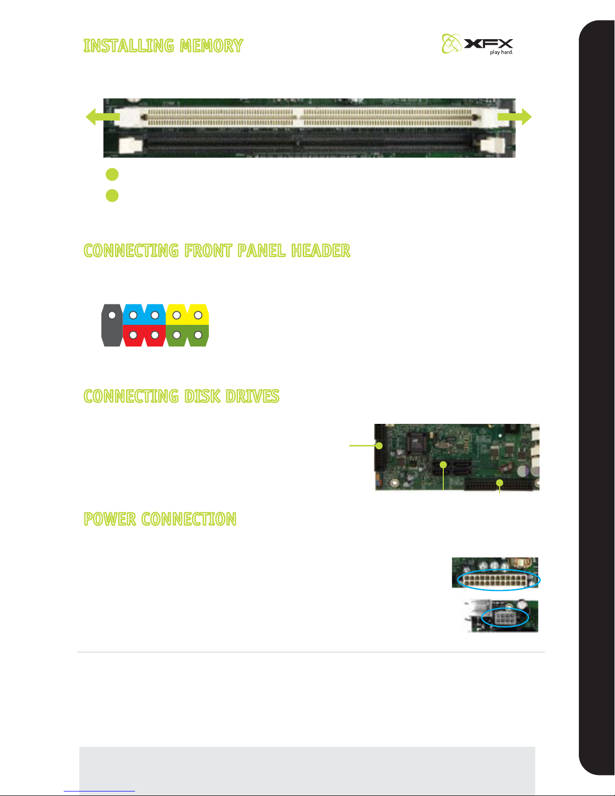
Unlock a DIMM slot by pressing the module clips outward.
Match the notch on the memory with the notch on the DIMM slot. Align the memory module to
the DIMM slot, and insert the module vertically into the DIMM slot. The plastic clips at both sides
of the DIMM slot automatically lock the DIMM into the connector.
DIMM Slot
RESET
PWRSWBlank
No Connect
PWRLED
– +
1
2
9
10
– +
HD_LED
INSTALLING MEMORYINSTALLING MEMORY
Refer to page 13 of the manual in the motherboard installation CD for additional details.
CONNECTING FRONT PANEL HEADERCONNECTING FRONT PANEL HEADER
Refer to page 19 of the manual in the motherboard installation CD for additional details.
CONNECTING DISK DRIVESCONNECTING DISK DRIVES
Refer to page 17 of the manual in the motherboard installation CD for additional details.
POWER CONNECTIONPOWER CONNECTION
Refer to page 16 of the manual in the motherboard installation CD for additional details.
1
2
Note: In general white and black wires are the negative leads (-) and the other colored
wires are the positive (+) leads. LED will not work if the negative and positive leads are
plugged in backwards.
SATA
Connectors
Floppy
Connectors
EIDE
Connectors
*The quick guides are used only for reference, please refer to the installation manual for detailed installation procedures.
This motherboard requires an ATX power supply.
Note: Power supply cables are design to fit the motherboard power
connectors in only one orientation.
• For general motherboard setup, make sure the 24-pin
ATX power connector, and the 8-pin 12V power
connector are properly connected to the power supply.
8-pin ATX 12 Power
Connector (PWR2)
24-pin ATX Power
Connector (PWR1)
To set up Raid using NVIDIA MediaShield Storage, refer to the manual in the motherboard installation CD.
(Page 82).
Please refer to the manufacture’s installation manual when installing any devices (i.e. graphics boards,
hard disk drives, optical drives, etc.) to the motherboard.


 User manual")