XLT Ovens XLT Gas Oven User manual

XLT Ovens
PO Box 9090
Wichita, Kansas 67277
TEL: 888-443-2751 FAX: 316-943-2769 WEB SITE: www.xltovens.com
XLT Oven & AVI Hood
Installation & Operation Manual
XD-9010B-GA
Rev 03 04/07/2011
2000887
This appliance is for professional use by qualified personnel. This appliance must be installed
by qualified persons in accordance with the regulations in force. This appliance must be installed with
sufficient ventilation to prevent the occurrence of unacceptable concentrations of substances harmful
to health in the room in which it is installed. This appliance needs an unobstructed flow of fresh air for
satisfactory combustion and must be installed in a suitably ventilated room in accordance with current
regulations. This appliance should be serviced by qualified personnel at least every 12 months or
sooner if heavy use is expected.
For use with the following AVI Hood Versions:
Standard (S) A
World (W) A
For use with the following XLT GAS Oven Versions:
Australian (AE) B
Standard (S) B
World (W) B
CAUTION
An electronic copy of this manual & warranty policy is available at: www.xltovens.com

2
WARNING & SAFETY INFORMATION
Post in a prominent location instructions to be followed in the event you smell gas. This infor-
mation can be obtained by consulting your local gas supplier.
FOR YOUR SAFETY
Do not store or use gasoline or other flammable
liquids or vapors in the vicinity of this or any other appliance.
Improper installation, adjustment, alteration, service or maintenance can cause prop-
erty damage, injury, or death. Read the installation, operating and maintenance in-
structions thoroughly before installing, using, or servicing this equipment.
In the event a gas odor is detected, shut off the gas at the main shutoff valve immediately.
Contact your local Gas Company or supplier.
Do not restrict the flow of combustion and/or ventilation air to the unit. Provide adequate
clearance for operating, cleaning, and maintaining the unit and adequate clearance for operat-
ing the gas shutoff valve when the unit is in the installed position.
Keep the area free and clear of combustible material. DO NOT SPRAY AEROSOLS IN THE
VICINITY OF THIS APPLIANCE WHILE IT IS IN OPERATION.
Ovens are certified for installation on combustible floors.
Electrical schematics are located inside the control box of the oven and at the end of this man-
ual. Disconnect input power to the unit before performing any maintenance.
This unit requires a Type I ventilation hood, which requires make-up and exhaust air to ensure
adequate air supply. The installation should conform to local codes.
This unit may be operated with either natural gas or LP fuel as designated on the nameplate
label located on the side of the unit.
This unit must be operated by the same voltage, phase, and frequency of electrical power as
designated on the nameplate label located on the side of the unit.
Minimum clearances must be maintained from combustible and non-combustible construction
materials.
Follow all local codes when installing this unit.
Follow all local codes to electrically ground the unit.
Appliance is not to be cleaned with high pressure water.
Ovens are certified for use in stacks of up to three (3) units of XLT products. Integration of
other manufacturer’s products into an oven stack is not recommended, and will void any war-
ranties. XLT Ovens assumes no liability for mixed product applications.
PLEASE RETAIN THIS MANUAL FOR FUTURE REFERENCE.
SAFETY DEPENDS ON YOU
WARNING
WARNING

3
For the best results with the XLT Oven and AVI Hood, carefully read this manual and all
of the warning labels attached to the products before installing and operating them, and follow the
instructions exactly. Keep this manual handy for quick reference.
Definitions and Symbols
A safety instruction (message) includes a “Safety Alert Symbol” and a signal word or
phrase such as WARNING or CAUTION. Each signal word has the following meaning:
Purchaser’s Responsibility
It is the responsibility of the purchaser:
To unload, uncrate, assemble, and move the ovens to their intended location.
To ensure that the gas and electric utilities are installed on site in accordance with local build-
ing codes and with the specifications in this manual.
To see that the gas and electric utilities are connected properly by a qualified installer using the
proper hardware.
To ensure a qualified installer has performed an initial start-up procedure.
In Australia, install oven in accordance with the latest version of AS5601 Gas Installation.
SAFETY MESSAGES
Tips give a special instruction that can save time or provide other benefits while installing or
using the product. The tip calls attention to an idea that may not be obvious to first-time us-
ers of the product.
TIP
NOTE
Notes indicates an area or subject of special merit, emphasizing either the product’s
capability or common errors in operation or maintenance.
CAUTION
Indicates a potentially hazardous situation, that if not avoided, can result in minor to
moderate injury or serious damage to the product. The situation described in the
CAUTION may, if not avoided, lead to serious results. Important safety measures are
described in CAUTION (as well as WARNING), so be sure to observe them.
WARNING
Indicates a potentially hazardous situation that, if not avoided, can result in serious
injury or death.
HIGH
VOLTAGE
This symbol indicates high voltage. It calls your attention to items or operations
that could be dangerous to you and other persons operating this equipment. Read
the message and follow the instructions carefully.

4
Receiving and Inspection
Upon receiving of all goods shipped by a Common Carrier, check for any exterior damage
that may indicate interior damage. If conditions permit, open all crates and do a full inspection for
any damage while the delivery driver is still there. If there is damage please note on the delivery
receipt and call the carrier to make a freight damage claim within 24 hours of receipt. Failure to
make a damage claim within the first 24 hours may void the opportunity to have the claim re-
solved.
Your new oven and hood system is the result of our dedication to help you produce the fin-
est quality baked goods. XLT Ovens has made a substantial and growing investment in capital
equipment and facilities, including state of the art CAD/CAM designing and fabricating software
and machine tools. The company has also developed ways to build quality into its products at each
stage of the manufacturing process, both through extensive use of automation and, most impor-
tantly, through an awareness that people are the central element in quality control.
XLT Ovens wants you to be totally satisfied with every aspect of owning and using your
oven and hood. Your feedback, both positive and negative, is very important to us as it helps us
understand how to improve our products and our company. Our goal is to provide you, our cus-
tomer, with equipment that we can be proud to build and you can be proud to own.
To receive technical support for the oven or hood you purchased, contact the designated
representative from whom you purchased the unit, or XLT Ovens at 888-443-2751 anytime day or
night, 365 days per year. Please be prepared to provide the Model and Serial Number.
Installation of all gas appliances and ventilation exhaust hoods should only be per-
formed by a qualified professional who has read and understands these instructions
and is familiar with proper safety precautions. Read this manual thoroughly before
installing or servicing this equipment.
Save this Manual
This document is the property of the owner of this equipment. Please make sure to leave
this copy with the store owner or “on site” manager, so it can be incorporated in the owners “on
site” book of manuals for future use.
XLT Ovens reserves the right to make changes in design and specifications, and/or make
additions to or improvements to its product without imposing any obligations upon itself to install
them in products previously manufactured.
NOTIFY CARRIER OF DAMAGE AT ONCE
WARNING
All Right and Left Hand designations in this manual are from the point of view as if stand-
ing directly in front of the ovens.

5
Warning & Safety Information..................................................................................................... 2
Safety Messages ........................................................................................................................... 3
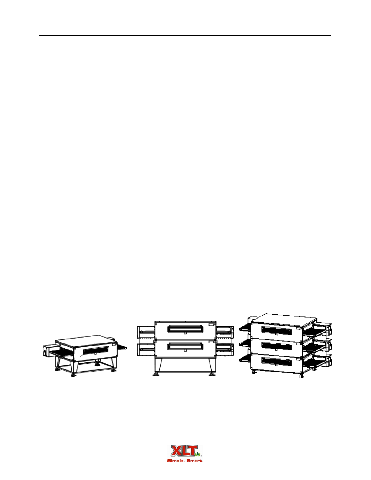
Oven Description.......................................................................................................................... 6
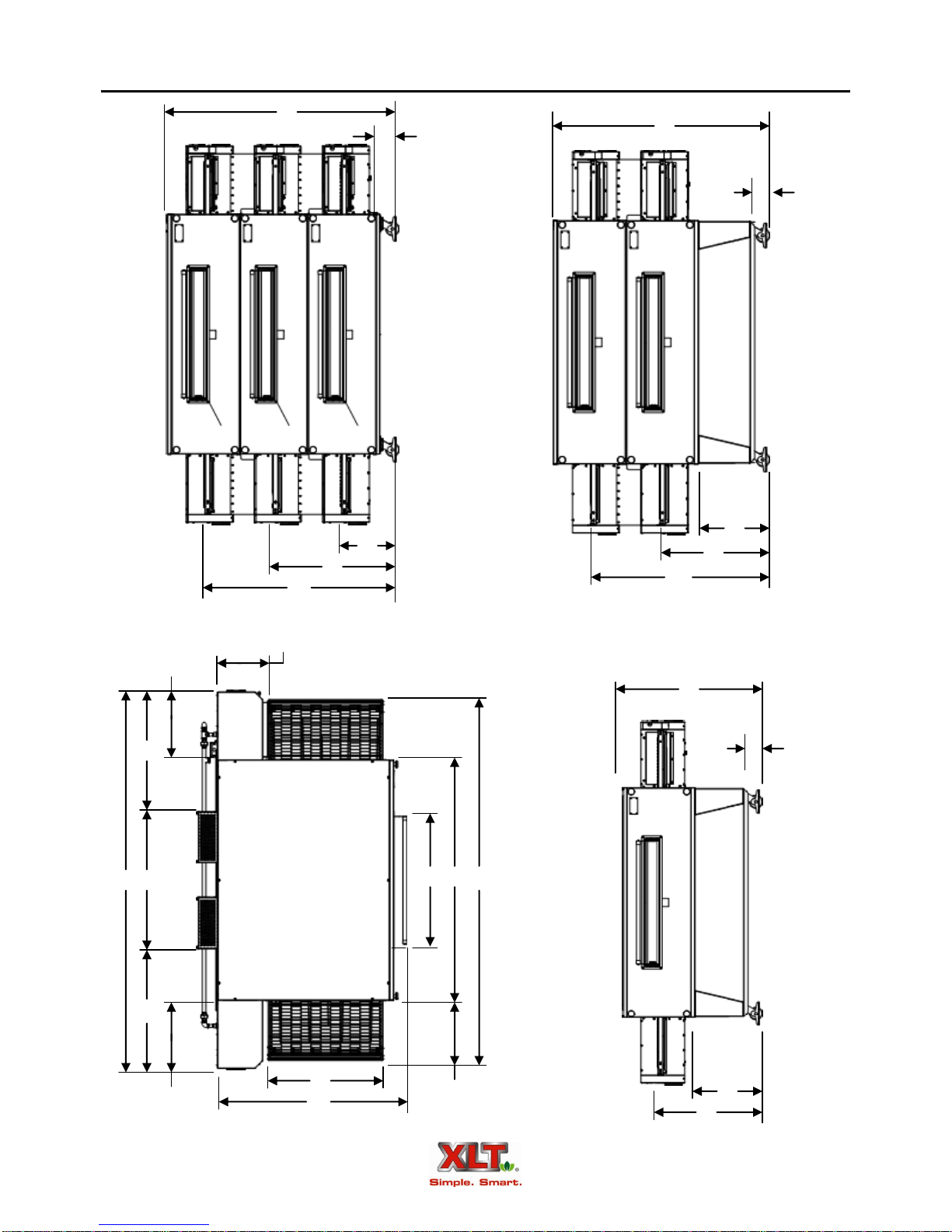
Oven Dimensions......................................................................................................................... 8
Gas & Electrical Connection Dimensions.................................................................................. 10
Oven Electrical Requirements.................................................................................................... 12
Oven Gas Requirements............................................................................................................. 13
Oven Only Rough-In Specifications ..........................................................................................15
Oven Assembly ..........................................................................................................................17
Oven Installation ........................................................................................................................ 23
Oven Ventilation Requirements & Guidelines........................................................................... 27
Oven Initial Start-Up.................................................................................................................. 29
Oven Operator Controls .............................................................................................................33
Oven Operation ..........................................................................................................................35
Oven Cleaning............................................................................................................................36
Oven Maintenance......................................................................................................................40
Oven Troubleshooting................................................................................................................ 41
Hood Description ....................................................................................................................... 44
Hood Dimensions.......................................................................................................................45
Hood Electrical Requirements................................................................................................... 47
Hood Ventilation Requirements................................................................................................. 64
Hood Rough-In Specifications...................................................................................................65
Hood Installation........................................................................................................................ 66
Variable Frequency Drive Adjustments..................................................................................... 85
Hood Operator Controls.............................................................................................................86
Hood Initial Start-Up.................................................................................................................. 87
Hood Valance Kit....................................................................................................................... 89
Hood Cleaning............................................................................................................................92
Hood Troubleshooting................................................................................................................94
International Distributors ...........................................................................................................94
Electrical Schematics .................................................................................................................95
Revision History Table
Revision Comments Date
01 Initial Release 1/19/2011
02 Updated Hood Installation Dimensions page 45 3/8/2011
03 Revised MJ/hr 04/07/2011
TABLE OF CONTENTS

6
Oven Description
1832B-W
2440B-W
3240B-W
3255B-W
3270B-W
3270SB-W
3855B-W
3870B-W
Food product is placed on the stainless steel wire conveyor belt on one side of the oven.
The conveyor then transports the food through the bake chamber at a user-controlled speed. This
provides repeatable and uniform food cooking. The conveyors can be easily configured to move
either left-to-right or right-to-left. A large center sandwich door allows the introduction or re-
moval of food items for cooking at shorter times. Temperatures up to 550º F or 288º C inside the
oven are achieved by means of a user-adjustable digital control.
The first 2 digits of the model number represent the conveyor width and the last two digits
indicate the bake chamber length. The ovens may be used in a single, double, or triple oven stack
configuration. A single or double configuration can be upgraded by adding additional decks up to
the maximum of three. All ovens are gas-fired and are available in Natural gas or LP gas models
(Electric ovens are also available). The 3270 and 3870 models have two burners, one on each side,
and have two control boxes. All other models have only a single burner with a single control box
that can be supplied on either end. All models can be configured for a split belt conveyor.
“-AE” indicates Australian Export configuration, certified to AGA AS 4563.
“-S” indicates Standard configuration, certified to ANSI Z83.11/CSA 1.8 & ANSI/NSF 4.
“-W” indicates World configuration, certified to CE GAD 90/396/EEC & BS EN 203-1.
This manual covers the following XLT Series Ovens and AVI Hood models:
1832-AE-B
2440-AE-B
3240-AE-B
3255-AE-B
3270-AE-B
3270S-AE-B
3855-AE-B
3870-AE-B
1832B-S
2440B-S
3240B-S
3255B-S
3270B-S
3270SB-S
3855B-S
3870B-S
AVI-1832A-S AVI-1832A-W
AVI-2440A-S AVI-2440A-W
AVI-3240A-S AVI-3240A-W
AVI-3255A-S AVI-3255A-W
AVI-3270A-S AVI-3270A-W
AVI-3855A-S AVI-3855A-W
AVI-3870A-S AVI-3870A-W
XLT Ovens are certified to the following Standards:
AVI Hoods are certified to the following Standards:
“-S” indicates Standard configuration, certified to UL 710, ULC-S646, NFPA 96, and ANSI/NSF 2.
“-W” indicates World configuration, certified to UL 710, ULC-S646, NFPA 96, and ANSI/NSF 2.

7
An easily removable front panel allows the full cleaning of the oven interior. All exposed
oven surfaces both exterior and interior are stainless steel. The conveyor is a one piece design and
is removed from the side which has the control box. No tools are required for disassembly and
cleaning of the conveyor or oven interior. The oven itself is mounted on lockable swivel casters
for easy moving and maintenance.
Accessories such as extended conveyor shelves and perforated crumb trays are available
from XLT. In addition, moving equipment such as carts and lifting jacks are available to help in-
stall and move ovens and hoods. Please contact XLT or your designated representative for more
information.
Oven Description
Oven Lid
Control Box (RH)
Control Box (LH)
(3270/3870 Only) Sandwich Door
Crumb Tray
Front Panel Knob
Single/Double Stack
Base Assembly Front Panel
Product Stop
Conveyor
Swivel Caster
Data Plate
Control
Box Lid
Chain Guard
Control
Panel
(RH)
Switch Control
Control Box Lid
Control
Panel
(LH)
Models 3270 & 3870 All Models

8
Oven Dimensions
M
N
K
L
M
N
K
L
P
N
P
K
L
Q
H
J
G F
B
C
D
* 19.77
[502] 19.77
[502]
17.55
[446]
A
E
20.87
[530]
NOTE: All dimensions in inches [mm].

9
TRIPLE
STACK A B C D E F G H J K L M N P Q WEIGHT
1832 19.41
[493] 32.13
[816] 67.25
[1708] 19.72
[501] 47.23
[1200] N/A* N/A* 39.92
[1014] 14.85
[377] 5.63
[143] 67.69
[1726] 20.66
[525] 16.75
[425] 36.73
[933] 56.72
[1441] 1240
[562]
2440 25.41
[645] 40.13
[1019] 75.25
[1911] 19.72
[501] 53.23
[1352] N/A* N/A* 39.92
[1014] 14.85
[377] 5.63
[143] 67.69
[1726] 20.66
[525] 16.75
[425] 36.73
[933] 56.72
[1441] 1500
[680]
3240 33.41
[849] 40.13
[1019] 75.25
[1911] 19.72
[501] 61.23
[1555] N/A* N/A* 39.92
[1014] 14.85
[377] 5.63
[143] 67.69
[1726] 20.66
[525] 16.75
[425] 36.73
[933] 56.72
[1441] 1830
[830]
3255 33.41
[849] 55.13
[1400] 90.25
[2292] 37.72
[958] 61.23
[1555] N/A* N/A* 39.92
[1014] 14.85
[377] 5.63
[143] 67.69
[1726] 20.66
[525] 16.75
[425] 36.73
[933] 56.72
[1441] 2100
[953]
3270 33.41
[849] 70.13
[1781] 105.25
[2673] 37.72
[958] 61.23
[1555] 109.72
[2787] 34.94
[887] 34.94
[887] 39.85
[1012] 5.63
[143] 67.69
[1726] 20.66
[525] 16.75
[425] 36.73
[933] 56.72
[1441] 2850
[1293]
3855 39.41
[1001] 55.13
[1400] 90.25
[2292] 37.72
[958] 67.23
[1708] N/A* N/A* 39.92
[1014] 14.85
[377] 5.63
[143] 67.69
[1726] 20.66
[525] 16.75
[425] 36.73
[933] 56.72
[1441] 2550
[1157]
3870 39.41
[1001] 70.13
[1781] 105.25
[2673] 37.72
[958] 67.23
[1708] 109.72
[2787] 34.94
[887] 34.94
[887] 39.85
[1012] 5.63
[143] 67.69
[1726] 20.66
[525] 16.75
[425] 36.73
[933] 56.72
[1441] 3300
[1497]
SINGLE
STACK A B C D E F G H J K L M N P Q WEIGHT
1832 19.41
[493] 32.13
[816] 67.25
[1708] 19.72
[501] 47.23
[1200] N/A* N/A* 39.92
[1014] 14.85
[377] 5.70
[145] 42.73
[1085] 20.66
[525] 31.78
[807] N/A N/A 500
[227]
2440 25.41
[645] 40.13
[1019] 75.25
[1911] 19.72
[501] 53.23
[1352] N/A* N/A* 39.92
[1014] 14.85
[377] 5.70
[145] 42.73
[1085] 20.66
[525] 31.78
[807] N/A N/A 600
[272]
3240 33.41
[849] 40.13
[1019] 75.25
[1911] 19.72
[501] 61.23
[1555] N/A* N/A* 39.92
[1014] 14.85
[377] 5.70
[145] 42.73
[1085] 20.66
[525] 31.78
[807] N/A N/A 720
[327]
3255 33.41
[849] 55.13
[1400] 90.25
[2292] 37.72
[958] 61.23
[1555] N/A* N/A* 39.92
[1014] 14.85
[377] 5.70
[145] 42.73
[1085] 20.66
[525] 31.78
[807] N/A N/A 850
[386]
3270 33.41
[849] 70.13
[1781] 105.25
[2673] 37.72
[958] 61.23
[1555] 109.72
[2787] 34.94
[887] 34.94
[887] 39.85
[1012] 5.70
[145] 42.73
[1085] 20.66
[525] 31.78
[807] N/A N/A 1100
[500]
3855 39.41
[1001] 55.13
[1400] 90.25
[2292] 37.72
[958] 67.23
[1708] N/A* N/A* 39.92
[1014] 14.85
[377] 5.70
[145] 42.73
[1085] 20.66
[525] 31.78
[807] N/A N/A 1050
[476]
3870 39.41
[1001] 70.13
[1781] 105.25
[2673] 37.72
[958] 67.23
[1708] 109.72
[2787] 34.94
[887] 34.94
[887] 39.85
[1012] 5.70
[145] 42.73
[1085] 20.66
[525] 31.78
[807] N/A N/A 1300
[590]
Oven Dimensions
NOTE: All dimensions in inches [mm]. All weights in pounds [kg].
DOUBLE
STACK A B C D E F G H J K L M N P Q WEIGHT
1832 19.41
[493] 32.13
[816] 67.25
[1708] 19.72
[501] 47.23
[1200] N/A* N/A* 39.92
[1014] 14.85
[377] 5.70
[145] 62.72
[1593] 20.66
[525] 31.78
[807] 51.77
[1315] N/A 890
[404]
2440 25.41
[645] 40.13
[1019] 75.25
[1911] 19.72
[501] 53.23
[1352] N/A* N/A* 39.92
[1014] 14.85
[377] 5.70
[145] 62.72
[1593] 20.66
[525] 31.78
[807] 51.77
[1315] N/A 1060
[481]
3240 33.41
[849] 40.13
[1019] 75.25
[1911] 19.72
[501] 61.23
[1555] N/A* N/A* 39.92
[1014] 14.85
[377] 5.70
[145] 62.72
[1593] 20.66
[525] 31.78
[807] 51.77
[1315] N/A 1300
[590]
3255 33.41
[849] 55.13
[1400] 90.25
[2292] 37.72
[958] 61.23
[1555] N/A* N/A* 39.92
[1014] 14.85
[377] 5.70
[145] 62.72
[1593] 20.66
[525] 31.78
[807] 51.77
[1315] N/A 1500
[680]
3270 33.41
[849] 70.13
[1781] 105.25
[2673] 37.72
[958] 61.23
[1555] 109.72
[2787] 34.94
[887] 34.94
[887] 39.85
[1012] 5.70
[145] 62.72
[1593] 20.66
[525] 31.78
[807] 51.77
[1315] N/A 2000
[907]
3855 39.41
[1001] 55.13
[1400] 90.25
[2292] 37.72
[958] 67.23
[1708] N/A* N/A* 39.92
[1014] 14.85
[377] 5.70
[145] 62.72
[1593] 20.66
[525] 31.78
[807] 51.77
[1315] N/A 1800
[816]
3870 39.41
[1001] 70.13
[1781] 105.25
[2673] 37.72
[958] 67.23
[1708] 109.72
[2787] 34.94
[887] 34.94
[887] 39.85
[1012] 5.70
[145] 62.72
[1593] 20.66
[525] 31.78
[807] 51.77
[1315] N/A 2300
[1043]
* Oven does not have left hand control box.

10
Gas & Electrical Connection Dimensions - Australian & World Ovens
8.21
[208]
9.85
[250]
28.19
[716]
29.83
[758]
48.18
[1224]
49.82
[1265]
9.30
[236]
18.91
[480]
23.24
[590]
24.88
[632]
43.23
[1098]
44.87
[1140]
9.30
[236]
18.91
[480]
9.30
[236]
18.91
[480]
23.24
[590]
24.88
[632]
NOTE: All dimensions in inches [mm].
For Models 3270 & 3870

11
For Models 1832, 2440, 3240, 3255 & 3855
25.24
[641]
24.88
[632]
12.35
[314]
18.91
[480]
Gas & Electrical Connection Dimensions - Australian & World Ovens
10.21
[259]
9.85
[250]
30.19
[767]
29.83
[758]
50.18
[1275]
49.82
[1265]
12.35
[314]
18.91
[480]
25.24
[641]
24.88
[632]
45.23
[1149]
44.87
[1140]
12.35
[314]
18.91
[480]
NOTE: All dimensions in inches [mm].

12
Oven Electrical Requirements
OVEN VOLTS AMPS FREQUENCY
Size
120 VAC
Single Double Triple
60 Hz
1832 6 12 18
2440 6 12 18
3240 6 12 18
3255 6 12 18
3270 12 24 36
3855 6 12 18
3870 12 24 36
Standard Ovens
OVEN VOLTS AMPS FREQUENCY
Size
220/230/240 VAC
Single Double Triple
50 / 60 Hz
1832 3 6 9
2440 3 6 9
3240 3 6 9
3255 3 6 9
3270 6 12 18
3855 3 6 9
3870 6 12 18
World Ovens
OVEN VOLTS AMPS FREQUENCY
Size
220/230/240 VAC
Single Double Triple
50 Hz
1832 3 6 9
2440 3 6 9
3240 3 6 9
3255 3 6 9
3270 6 12 18
3855 3 6 9
3870 6 12 18
Australian Ovens

13
Inlet Pressure
Oven Burner Max. Capacity NAT Gas LP Gas
Size BTU/HR KW/HR MJ/HR W/C mbar kPa W/C mbar kPa
1832 52,000 15.24 63 6-14 15-35 1.5-3.5 11.5-14 27.5-35 2.75-3.5
2440 65,000 19.05 79 6-14 15-35 1.5-3.5 11.5-14 27.5-35 2.75-3.5
3240 90,000 26.37 105 6-14 15-35 1.5-3.5 11.5-14 27.5-35 2.75-3.5
3255 150,000 43.95 169 6-14 15-35 1.5-3.5 11.5-14 27.5-35 2.75-3.5
3270 160,000 46.88 190 6-14 15-35 1.5-3.5 11.5-14 27.5-35 2.75-3.5
3855 150,000 43.95 169 6-14 15-35 1.5-3.5 11.5-14 27.5-35 2.75-3.5
3870 160,000 46.88 190 6-14 15-35 1.5-3.5 11.5-14 27.5-35 2.75-3.5
Manifold Pressure Orifice Sizes
Standard & World
Orifice Size
Australia
Oven Natural Gas LP Gas Natural Gas LP Gas Natural
Gas
LP
Gas
Size W/C mbar kPa W/C mbar kPa Inches MM Inches MM MM MM
1832 3.5 8.75 .875 10 25 2.5 .1285 3.26 .0820 2.08 3.56 2.24
2440 3.5 8.75 .875 10 25 2.5 .144 3.66 .0890 2.26 3.96 2.44
3240 3.5 8.75 .875 10 25 2.5 .1695 4.3 .1040 2.64 4.62 2.79
3255 3.5 8.75 .875 10 25 2.5 .219 5.56 .1285 3.26 5.94 3.66
3270 3.5 8.75 .875 10 25 2.5 .147 3.73 .0980 2.49 4.39 2.64
3855 3.5 8.75 .875 10 25 2.5 .219 5.56 .1285 3.26 5.94 3.66
3870 3.5 8.75 .875 10 25 2.5 .147 3.73 .0980 2.49 4.39 2.64
Gas RequirementsAustralian, Standard. & World
All values shown this page are per each oven

14
Natural Gas (8.75 mbar manifold) LP Gas (25 mbar manifold)
Country Symbol I2H I2L I2E I2E+ I3B/P I3+ I3P
Germany DE X X X
Austria AT X X
Belgium BE X X
Denmark DK X X
Spain ES X X X
Finland FI X X
France FR X X X X
Greece GR X
Ireland IE X X X
Iceland IS
Italy IT X X
Luxembourg LU
Norway NO X
Netherlands NL X X X
Portugal PT X X X
United Kingdom GB X X X
Sweden SE X X
Switzerland CH X X X X
Slovenia SI X
Slovakia SK X
Cyprus CY X X X
Estonia EE X
Latvia LT X
Lithuania LV
Malta MT X X
Hungary HU X X
Poland PL X
Czech Republic CZ X X
Natural Gas Propane Gas
Gas Group I2H I2E I2E+ I2L I3+ I3B/P (30) I3P
(30/37/50)
I3B (37)
Inlet pressure (mbar) 20 20 20/25 25 28/30/37/50 28-30/37/50 30/37/50 37
Number of injectors (1) per burner
Main burner opening size Fixed
Ignition Electric Direct Spark Igniter
Inlet connection BSP 3/4" male thread
World Oven Gas Group
Gas Matrix by Country

15
The gas supply and the electrical supply are to be provided by the customer prior to instal-
lation. The picture shows a typical utility rough-in for a triple stack oven. Preparing the utilities
this way allows for an easy third deck addition if a double stack oven is initially installed.
All installations must conform to local building and mechanical codes. It is required that
the ovens be placed under a ventilation hood. The gas supply should have a gas meter and regula-
tor large enough to handle all of the gas appliances, such as the furnace, hot water heater, and ov-
ens, in operation at the same time. Add up all of the BTU / kw / MJ ratings to determine the total
load. (See Oven Specifications page for supply requirements).
Oven Only Rough-In Specifications
1. All dimensions in inches [mm].
2. All dimensions on this page are recommended.
42.00
[1067]
48.00
[1219]
6.00
[152]
3.00
[76] Electrical Supply
Gas Manifold
6.00 [152]
From back of oven to wall
Utilities must be easily accessible when the ovens are in the installed position. Do not install utilities
behind the ovens.
NOTE
NOTE

16
Do not use Teflon tape on gas line connections as this can possibly cause gas valve
malfunction or plugging of orifices from shreds of tape. Use of Teflon tape may af-
fect warranty.
FOR EACH OVEN:
Electrical service for Standard Ovens must be 120VAC, 20 A, 60 Hz single phase circuits
with ground.
Electrical service for World Ovens must be 220/230/240VAC, 10 A, 50/60 Hz single phase
circuits with ground.
Electrical service for Australian Ovens must be 220/230/240 VAC, 10 A, 50Hz single
phase and installed in accordance with the latest version of AS/NZS 3000 wiring rules.
A separate circuit breaker must be provided for each oven deck.
Gas and electric connections must be accessible when the ovens are in the installed position.
Electrical plugs and cords must meet all local code requirements.
Gas hose assemblies with quick disconnects for each oven deck will be installed at each valve.
Oven Only Rough-In Specifications
Item # Description
1 1-½ [40] Shut-Off Valve
2 ¾ [20] Shut-Off Valve
3 6 [150] Nipple
4 ¾ [20] Nipple
5 Reducing Tee
6 Tee
7 Cap
8 Plug
All pipe fittings to be 1-½ [40] minimum
unless noted. NPT & BSP
1
3
2
4 5
6
7
8
3
3
4
CAUTION
NOTE
NOTE: All dimensions in inches [mm].

17
OvenAssembly
XLT ovens can easily be moved and stacked with the proper lifting equipment. The use of
lifting equipment is highly recommended.
WARNING & SAFETY INFORMATION
Base Assembly - Triple Stack
1. Flip the oven base upside down on the floor.
2. For triple-stack configurations, attach the four casters directly to the base with the supplied
3/8" x 1" hex bolts, washers, and lock-washers.
3. Flip the base assembly over and ensure the insulation is placed properly.
These ovens are heavy and can tip or fall causing bodily injury.
NEVER place any part of your body beneath any oven that is suspended by the
lifting jacks. A crush hazard exists if the oven falls or slips.
DO NOT place your hands on the lifting jack vertical pole beneath the jack’s
winch. As the jack’s winch descends when you turn the jack handle, a pinch
point is created between the winch and the pole.
WARNING
BE CAREFUL when rolling the oven on the cart, especially when going up or down
ramps and over bumps. Leave the straps/banding on until the oven is near the assem-
bly area.
CAUTION

18
OvenAssembly
Leg Angle
Leg
1. Flip the oven base upside down on the floor.
2. For single and double-stack configurations, attach the four legs to the bottom of the base with
the supplied 3/8" x 1" hex bolts, washers, and lock-washers. Do not fully tighten them at this
time. Leave them slightly loose so that the rest of the components can be more easily assem-
bled.
3. Place the four leg angles on top of the legs as shown. All of the leg angle holes should line up
with the holes in the bottom of the legs. Place two (2) washers on each leg at the inner corner
holes. These 2 washers are approximately the same thickness as the leg angles, and will keep
the caster level.
4. Attach the four casters to the legs as shown. The leg angles and washers are sandwiched be-
tween the casters and the leg base plates.
5. Tighten all fasteners.
6. Flip the base assembly over and ensure the insulation is placed properly.
Base Assembly - Single & Double Stack

19
Prepare the Oven for Lifting
1. Remove the two conveyor opening flaps and thumbscrews from the oven. Set them aside for
reinstallation later.
2. Install the lifting plates in place of the conveyor opening flaps using the same thumbscrews.
OvenAssembly
Conveyor
Opening Flap
Thumb
Screws Conveyor
Opening Flap
Thumb
Screws
Right Hand
Lifting Plate
Thumb
Screws
Thumb
Screws
Left Hand
Lifting Plate
The Lifting Pipe hole, marked for the appropriate oven size, must be installed closest
to the control box.
NOTE
NOTE
If using an AVI Hood System, conveyor flaps are not needed.
Top of Oven
Top of Oven

20
Lifting Jack Setup
Each lifting jack consists of two (2) parts; the pole/winch assembly, and the tripod base.
OvenAssembly
Lifting Pipe
Top of Oven
Jack
Cart
Bands
Front of Oven
2. Insert the lifting pipe through the oven bake chamber. Make sure the pipe is centered.
Make sure that the notch on tube of the winch assembly is aligned with the pin
in the tripod base as shown. These alignments are important and keep the jack
aligned properly.
Check for smooth operation. The cable should not be pinched and should pass
smoothly over the pulley on top of the pole assembly.
Inspect cable prior to each use.
If cable is frayed or shows signs of excessive wear and tear, DO NO USE until
cable is replaced.
At a minimum replace the cable annually with wire rope that meets or exceeds
the jack manufacturer’s specifications.
Do not exceed the stated capacity of the jack.
WARNING
1. Place the bottom of the pole into the socket of the tripod base.
Illustrations shown with XLT Oven on Cart, instructions also apply when oven is crate shipped.
Other manuals for XLT Gas Oven
2
This manual suits for next models
39
Table of contents
Other XLT Ovens Oven manuals

XLT Ovens
XLT Ovens TS3-W World Series User manual

XLT Ovens
XLT Ovens XD 9004G User manual

XLT Ovens
XLT Ovens RD 9007 PS Quick start guide

XLT Ovens
XLT Ovens XP-5201-208-4.5 Quick start guide

XLT Ovens
XLT Ovens 1832 Quick start guide

XLT Ovens
XLT Ovens XLT Gas Oven Quick start guide

XLT Ovens
XLT Ovens XLT Gas Oven User manual

XLT Ovens
XLT Ovens H3E-1832 Series User manual

XLT Ovens
XLT Ovens XD 9006B Quick start guide

XLT Ovens
XLT Ovens X3F3-1832 Series User manual