xCORE-200 explorerKIT Hardware Manual
IN THIS DOCUMENT
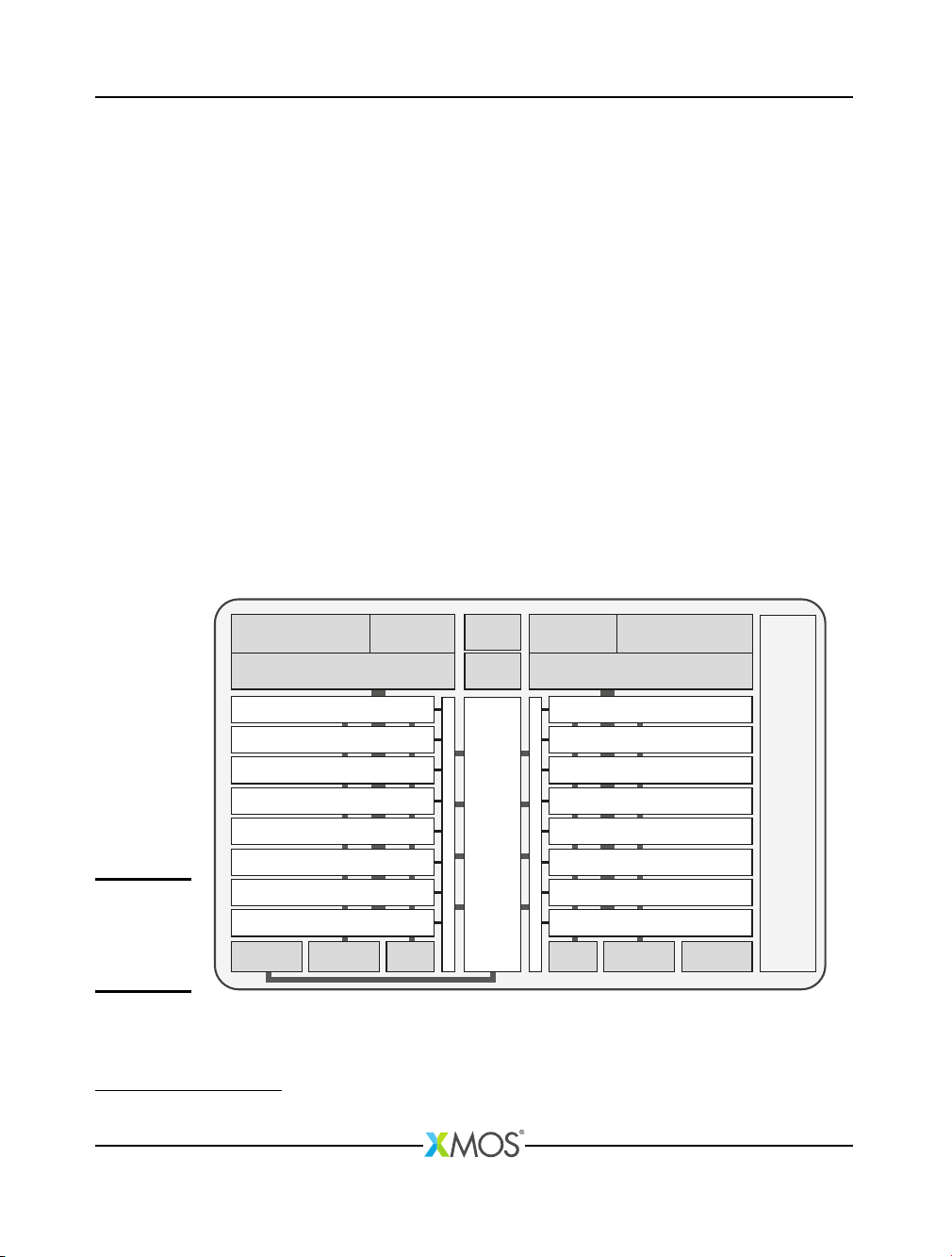
·Features
·xCORE Multicore Microcontroller Device
·GPIO headers (J1 & J3)
·Gyroscope and accelerometer
·USB connections
·RGMII connection
·xSYS connector
·General purpose push-button switches
·Servo connectors
·User LEDs
·QSPI Flash
·24MHz Crystal Oscillator
·Power connector
·Operating requirements
·Dimensions
·xCORE-200 explorerKIT Portmap
·xCORE-200 explorerKIT schematics
·RoHS and REACH
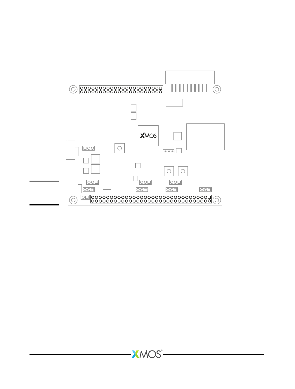
xCORE-200 explorerKIT is an evaluation board for the configurable xCORE-200
multicore microcontroller products from XMOS. It’s easy to use and provides lots
of advanced features on a small, extremely low cost platform.
xCORE lets you software-configure the interfaces that you need for your system;
so with xCORE-200 explorerKIT you can configure the board to match your exact
requirements. The xCORE-200 multicore microcontroller has sixteen 32bit logical
cores that deliver up to 2000MIPs completely deterministically, making xCORE-200
explorerKIT an ideal platform for functions ranging from robotics and motion
control to networking and digital audio.
Publication Date: 2015/7/27 Document Number: XM007647C
XMOS © 2015, All Rights Reserved