XMOS XK-1A User manual

XK-1A Development Board Tutorial
IN THIS DOCUMENT
·Introduction
·Illuminate an LED
·Flash an LED
·Flash and cycle LEDs at different rates
·Run tasks concurrently
·What to read next
1 Introduction
The XK-1A is a low-cost development board based on the XMOS XS1-L1 device. It
includes a single L1, four LEDs, two press-buttons, SPI flash memory, two 16-way
IDC connectors and an XSYS debugging interface.
This tutorial shows you how to write some simple XC programs that control and
respond to the XK-1A board components. In this tutorial you learn how to:
·illuminate the LEDs
·flash the LEDs at a fixed rate
·flash the LEDs in sequence
·respond to a button press
·connect multiple boards together
2 Illuminate an LED
This part of the tutorial shows you how to illuminate an LED on your XK-1A, using
an XC port and an output statement.
2.1 Create a project
2.2 Add the application code
The program below illuminates an LED on an XK-1A.
# i nc lude < xs1 .h >
out port led = XS1_ POR T_4 F ;
Publication Date: 2012/11/8 Document Number: X7366A
XMOS © 2012, All Rights Reserved

XK-1A Development Board Tutorial 2/20
int m ain () {
led <: 0 b0001 ;
while (1)
;
return 0;
}
Copy and paste the code into your project, and then choose
File ·Save
() to save
your changes to file.
2.3 Examine the code
Take a look at the code in the editor. The declaration
out port led = XS1_PORT_4F;
declares an output port named
led
, which refers to the 4-bit port 4F. On the XK-1A,
the I/O pins of port 4F are connected to the LEDs labeled LED0, LED1, LED2 and
LED3.
Show image of port map..
XS1_PORT_4F[1]
LED0
LED1
LED2
LED3
BUT1
BUT2
XS1_PORT_4F[0]
XS1_PORT_4F[2]
XS1_PORT_1L
XS1_PORT_1K
XS1_PORT_4F[3]
XS1-L1
X7366A

XK-1A Development Board Tutorial 3/20
XC input and output statements make it easy to express I/O operations on ports.
The statement
led <: 0b0001;
causes the value specified to the right of
<:
to be output to the port specified to
its left (
led
). The port then drives LED0 high and the other LEDs low, causing LED0
to illuminate yellow and the other LEDs to remain off.
The empty
while
loop prevents the program from terminating, which ensures that
the LED remains illuminated.
2.4 Build and run your project
To build and run your project, follow these steps:
1.
In the
Project Explorer
, click your project to select it, and then choose the
menu option Project ·Build Project ( ).
The XDE displays its progress in the
Console
. When the build is complete, the
XDE adds the compiled binary file to the subfolder bin/Debug.
2. Choose Run ·Run Configurations.
3.
In the
Run Configurations
dialog, in the left panel, double-click
XCore Appli-
cation.
4. In the right panel, in Name, enter the name illuminate.
X7366A

XK-1A Development Board Tutorial 4/20
5.
In
Project
, ensure that your project is displayed. If not, click
Browse
to open
the Project Selection dialog, select your project, and then click OK.
6.
In
C/C++ Application
, click
Search Project
to open the
Program Selection
dialog, select your application binary, and then click OK.
7.
In
Device options
, in
Run on
, select the option
hardware
, and in
Target
,
ensure that the option “XMOS XTAG-2 connected to L1[0]” is selected.
If your hardware is not displayed, ensure that your XK-1A is connected to your
PC, and then click Refresh list.
8. Click Run to save your configuration and run it.
The XDE loads the binary onto your XK-1A, displaying its progress in the
Console. When the binary is loaded, the Console is cleared.
9. On your XK-1A, verify that LED0 is illuminated yellow.
10.
In the
Console
, click the
Terminate
button () to stop your application running.
2.5 Exercise
To complete this part of the tutorial, perform the following steps:
1. Modify your application so that it illuminates all four LEDs.
Show a tip..
You should change the value output to the port
led
so that all four LEDs are
driven high.
Show a sample answer..
# i nc lude < xs1 .h >
out port led = XS1_ POR T_4 F ;
int m ain () {
led <: 0 b1111 ;
while (1)
;
return 0;
}
2. Click the Run button ( ) to reload your last Run Configuration.
The XDE determines that your source code has been updated and re-builds it,
displaying progress in the Console.
If your application contains errors, the XDE displays a dialog asking if you want
to continue launching the application. Click
No
, locate the first error in the
Console
and double-click it to go to the offending line in the editor. When you
have fixed all errors, re-run your application.
X7366A

XK-1A Development Board Tutorial 5/20
3.
On your XK-1A, verify that all four LEDs are illuminated, and then click the
Terminate button () to stop your application running.
3 Flash an LED
This part of the tutorial shows you how to flash an LED at a fixed rate, using an XC
timer and an input statement.
3.1 Create a new project
3.2 Add the application code
The program below flashes a single LED on an XK-1A.
# i nc lude < xs1 .h >
# defin e FL ASH_ PERIO D 20 000000
out port led = XS1_ POR T_4 F ;
int main ( void ) {
time r tmr ;
unsi gne d isOn = 1;
unsi gne d t;
tmr : > t;
while (1) {
led <: isOn ;
t += FLASH_PERIOD;
tmr when t imer afte r (t ) :> void ;
isOn = !isOn;
}
return 0;
}
Copy and paste the code into your project, and then choose
File ·Save
() to save
your changes to file.
3.3 Examine the code
Take a look at the code in the editor. The declaration
timer tmr;
declares a variable named
tmr
, and allocates an available hardware timer. The L1
provides 10 timers, which can be used to determine when an event happens, or to
delay execution until a particular time. Each timer contains a 32-bit counter that is
incremented at 100MHz and whose value can be input at any time.
The statement
tmr :> t;
X7366A

XK-1A Development Board Tutorial 6/20
inputs the value of
tmr
‘s counter into the variable
t
. Having recorded the current
time, the statement
t += FLASH_PERIOD;
increments this value by the required delay, and the statement
tmr when timerafter(t) :> void;
delays inputting a value until the specified time is reached. The input value is not
needed, which is expressed as an input to void.
3.4 Build and run your project
To build and run your project, follow these steps:
1.
In the
Project Explorer
, click your project to select it, and then choose the
menu option Project ·Build Project ( ).
The XDE builds your project, displaying its progress in the
Console
. When
the build is complete, the XDE adds the compiled binary file to the application
subfolder bin/Debug.
2. Create a new Run Configuration for your application named flash, and run it.
Show reminder..
Follow these steps:
3. Choose Run ·Run Configurations.
4.
In the
Run Configurations
dialog, in the left panel, double-click
XCore Appli-
cation.
5. In the right panel, in Name, enter the name flash.
6.
In
Project
, ensure that your project is displayed. If not, click
Browse
to open
the Project Selection dialog, select your project, and then click OK.
7.
As there are now two applications in your project, the XDE is unable to select
one automatically. To select, in
C/C++ Application
, click
Search Project
to
open the
Program Selection
dialog, select your application binary, and then
click OK.
8.
In
Device options
, in
Run on
, select the option
hardware
, and in
Target
,
ensure that the option “XMOS XTAG-2 connected to L1[0]” is selected.
If you did not stop your previous application running, your hardware may be
displayed as “XMOS XTAG-2 connected to None”.
9. Click Run to save your configuration and run it.
The XDE loads the binary onto your XK-1A, displaying its progress in the
Console. When the binary is loaded, the Console is cleared.
X7366A

XK-1A Development Board Tutorial 7/20
10.
On your XK-1A, verify that LED0 is flashing on-off, and then click the
Terminate
button () to stop your application running.
3.5 Switch between projects
The
Run
button ( ) can be used to switch between projects. To complete this
part of the tutorial, follow these steps:
1.
Click the arrow to the right of the
Run
button and select the Run Configuration
named illuminate.
2. On your XK-1A, verify that all four LEDs are illuminated.
3.
Click the arrow to the right of the
Run
button and select the Run Configuration
named flash.
4. On your XK-1A, verify that LED0 is flashing on-off.
5.
Modify the source of the flashing LED application to change the value of
FLASH_PERIOD from 20000000 to 40000000.
6. To build and run, just click the Run button.
The XDE launches the Run Configuration you most recently selected.
7.
On your XK-1A, verify that LED0 is flashing on-off at half the rate it was flashing
previously, and then click the
Terminate
button () to stop your application
running.
3.6 Exercise
To complete this part of the tutorial, perform the following steps:
1.
Modify your flashing LED application so that both LED0 and LED1 are flashed,
with LED0 flashed twice as fast as LED1.
Show a tip..
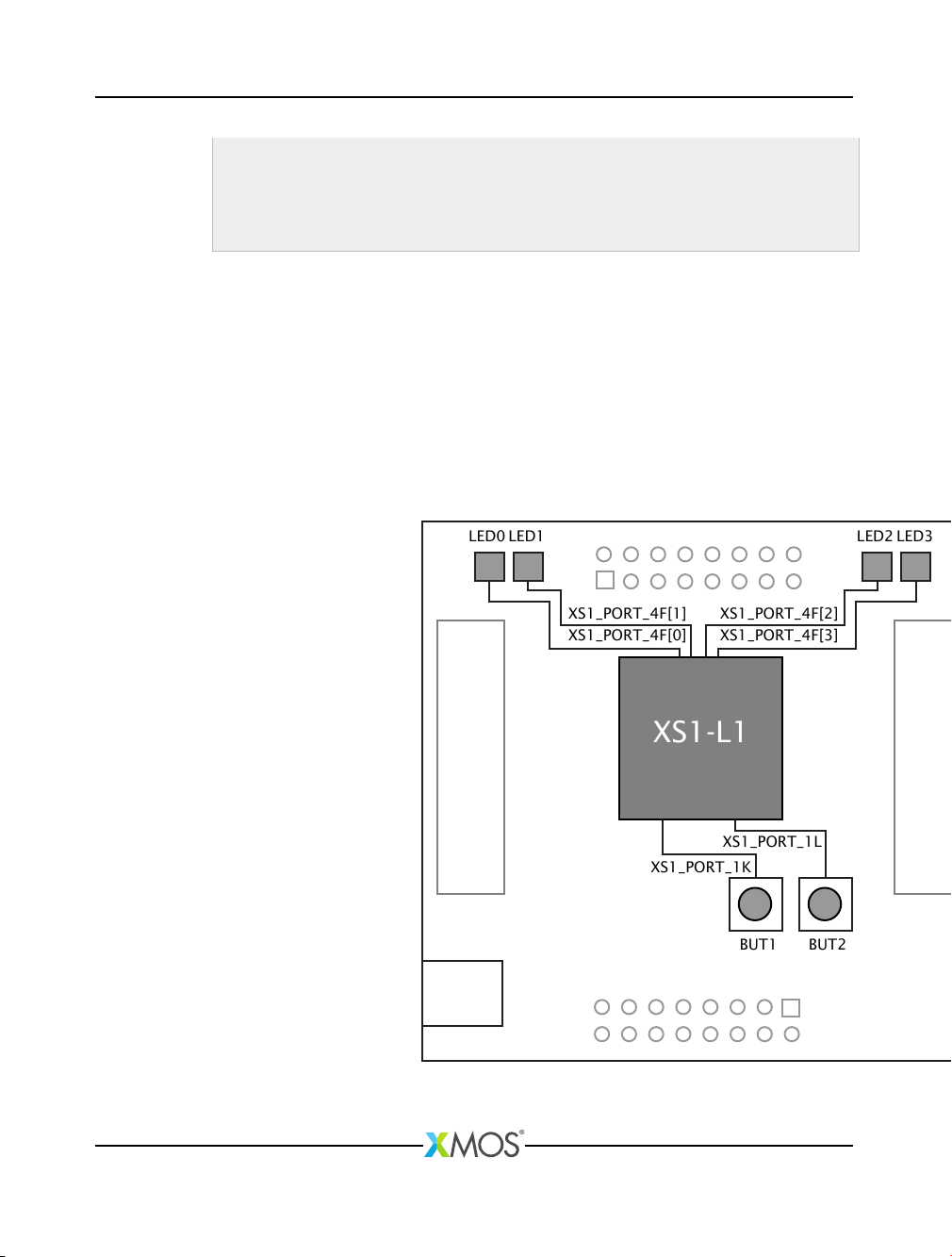
You should output the following pattern to the port
led
: 0b0011, 0b0010,
0b0011, 0b0010, 0b0001, 0b0000, 0b0001 and 0b0000.
Explain the solution in more detail..
You can define an array of integers an initialize it with the values 0b0011,
0b0010, 0b0011, 0b0010, 0b0001, 0b0000, 0b0001 and 0b0000. Then use a
loop to output this sequence of values to the port 4F.
Show a sample answer..
# i nc lude < xs1 .h >
# defi ne FL ASH_ PERIO D 20 000000
out port led = XS1_ POR T_4 F ;
X7366A

XK-1A Development Board Tutorial 8/20
int patt ern [] = {0 b0011 ,
0b0010 ,
0b0011 ,
0b0010 ,
0b0001 ,
0b0000 ,
0b0001 ,
0 b0000 };
int main ( void ) {
time r tmr ;
unsi gne d t;
unsi gne d i = 0;
tmr : > t;
while (1) {
t += FLASH_PERIOD;
tmr when t imer afte r ( t) :> v oid ;
led <: p att ern [ i ];
i = (i +1) % 8;
}
return 0;
}
2. Run your application.
3.
On your XK-1A, verify that the two LEDs are flashing at different speeds, and
then click the Terminate button () to stop your application running.
4 Flash and cycle LEDs at different rates
This part of the tutorial shows you how to flash an LED while cycling it along the
LEDs on your XK-1A.
4.1 Create an application
The program below inputs from one of two timers in a loop.
# i nc lude < xs1 .h >
# defin e FL ASH_ PERIO D 10 000000
# defin e CY CLE_ PERIO D 50 000000
out port led = XS1_ POR T_4 F ;
int main ( void ) {
timer tmrF , t mrC ;
uns igned timeF , t imeC ;
tmrF : > time F ;
tmrC : > time C ;
while (1) {
X7366A

XK-1A Development Board Tutorial 9/20
select {
case tmrF w hen tim eraf ter ( timeF ) : > void :
/* add code to re spon d to ti meout */
break ;
case tmrC w hen t imer af te r ( timeC ) :> void :
/* add code to re spon d to ti meout */
break ;
}
}
return 0;
}
Before continuing to the next part of this tutorial, create a new project using this
code.
4.2 Examine the application code
Take a look at the application code in the editor. The first statement in
main
inputs
the value of the timer
tmrF
into the variable
timeF
, and the second statement
inputs the value of the timer tmrC into the variable timeC.
In the
while
loop, the
select
statement waits for the an input on either
tmrF
or
tmrC
to become ready. It then performs the selected input and executes any code
after it up until the keyword break.
If more than one input becomes ready at the same time, only one is executed in a
single iteration of the loop; the other input is selected on the following iteration.
4.3 Exercise 1
To complete this part of the tutorial, perform the following tasks:
1. Modify the application so that:
·
On each input from
tmrC
, the program changes which LED is flashed, cycling
between all four LEDs in sequence.
·
On each input from
tmrF
, the program changes the state of the current LED
bewteen on and off.
Show a sample answer..
# i nc lu de < x s1 . h >
# defin e FL AS H_ PE RIOD 100 000 00
# defin e CY CL E_ PE RIOD 500 000 00
out port led = XS 1_P ORT _4F ;
in t main ( v oid ) {
unsi gne d led On = 1;
unsi gne d le dVal = 1;
X7366A

XK-1A Development Board Tutorial 10/20
timer tmrF , t mrC ;
uns ig ne d timeF , time C ;
tmrF : > time F ;
tmrC : > time C ;
while (1) {
select {
case tmrF w hen t imer af te r ( timeF ) :> void :
ledOn = ! le dOn ;
if ( l edOn )
led <: l edVa l ;
else
led <: 0;
timeF += FL AS H_ PER IO D ;
break ;
case tmrC w hen t imer af te r ( timeC ) :> void :
ledVa l <<= 1;
if ( le dV al == 0 x10 )
ledVal = 1;
timeC += CY CL E_ PER IO D ;
break ;
}
}
return 0;
}
2. Build your project, create a new Run Configuration, and run it.
Show reminder..
Follow these steps:
3.
In the
Project Explorer
, click your project to select it, and then choose the
menu option Project ·Build Project ( ).
If any errors are reported in the
Console
, double-click an error to locate it in
the editor, fix the error and then re-build your application.
4. Choose Run ·Run Configurations.
5.
In the
Run Configurations
dialog, in the left panel, double-click
XCore Appli-
cation.
6. In the right panel, in Name, enter a name for the Run Configuration.
7.
In
Project
, ensure that your project is displayed. If not, click
Browse
to open
the Project Selection dialog, select your project, and then click OK.
8.
In
C/C++ Application
, click
Search Project
to open the
Program Selection
dialog, select your application binary, and then click OK.
9.
In
Device options
, in
Run on
, select the option
hardware
, and in
Target
,
ensure that the option “XMOS XTAG-2 connected to L1[0]” is selected.
X7366A

XK-1A Development Board Tutorial 11/20
10. Click Run to save your configuration and run it.
The XDE loads the application binary onto your XK-1A, displaying its progress
in the Console. When the binary is loaded, the Console is cleared.
11.
On your XK-1A, verify that a flashing LED is cycled between the four LEDs, and
then click the Terminate button () to stop your project running.
4.4 Exercise 2
To complete this part of the tutorial, perform the following tasks:
1.
Add an additional case to the
select
statement that responds to Button 1 being
pressed by displaying the string “pressed” on the console, and then waits for
Button 1 to be released and displays the string “released”.
Note that Button 1 drives a 1-bit port high. Pressing the button causes it to stop
driving the port, and releasing results in it driving again. You can test for these
conditions using the input condition pinseq(0) and pinseq(1).
Show image of port map..
XS1_PORT_4F[1]
LED0
LED1
LED2
LED3
BUT1
BUT2
XS1_PORT_4F[0]
XS1_PORT_4F[2]
XS1_PORT_1L
XS1_PORT_1K
XS1_PORT_4F[3]
XS1-L1
To print a message to the console, you can include the standard C library header
stdio.h and use the the library function printf.
Explain the solution in more detail..
X7366A

XK-1A Development Board Tutorial 12/20
Follow these steps:
2. At the top of your source file, include the header file stdio.h.
3. Define an input port named but1 and initialize it with the value XS1_PORT_1K.
4. In the select statement, add the following case statement:
case but1 when pinseq(0) :> void:
5.
In the body of this case, first call the function
printf
to display the first message;
then input from the button when the value sampled on the pin equals 1; and
then call printf again to display the second message.
Show a sample answer..
# i nc lu de < x s1 . h >
# i nc lu de < s tdio . h >
# defin e FL AS H_ PE RIOD 100 000 00
# defin e CY CL E_ PE RIOD 500 000 00
out port led = XS 1_P ORT _4F ;
in port b ut1 = XS1 _P ORT _1 K ;
in t main ( v oid ) {
unsi gne d led On = 1;
unsi gne d le dVal = 1;
timer tmrF , t mrC ;
uns ig ne d timeF , time C ;
tmrF : > time F ;
tmrC : > time C ;
while (1) {
select {
case tmrF w hen t imer af te r ( timeF ) :> void :
ledOn = ! le dOn ;
if ( l edOn )
led <: l edVa l ;
else
led <: 0;
timeF += FL AS H_ PER IO D ;
break ;
case tmrC w hen t imer af te r ( timeC ) :> void :
ledVa l <<= 1;
if ( le dV al == 0 x10 )
ledVal = 1;
timeC += CY CL E_ PER IO D ;
break ;
case but1 w hen p in se q (0) : > vo id :
print f (" P res sed \ n" );
but1 when pi nse q (1) : > vo id ;
print f (" R ele as ed \ n") ;
X7366A

XK-1A Development Board Tutorial 13/20
break ;
}
}
return 0;
}
6. Run your application.
A flashing LED should cycle between the four LEDs on your XK-1A.
7.
Verify that pressing and holding button BUT1 causes the message “pressed” be
displayed in the
Console
and the LEDs to stop flashing. Releasing the button
should cause the message “released” to be displayed and the flashing LED
should continue cycling.
Note that you may need to push the button down firmly on your XK-1A to
operate it.
8.
In the
Console
, click the
Terminate
button () to stop your application running.
5 Run tasks concurrently
This part of the tutorial shows you how to run tasks concurrently on different
threads, using the XC par statement and channel communication.
5.1 Create a project
The program below creates two concurrent threads, which run two separate tasks
independently of each other.
# i nc l ud e < xs 1 .h >
# i nc l ud e < s tdi o . h >
# de fine FL ASH_ PER IOD 10000000
# de fine CY CLE_ PER IOD 50000000
out port led = XS1 _ P O R T _ 4 F ;
in p ort but1 = XS1_PORT_1K ;
void f l a s hLEDs4 b i t P ort ( out po rt led , int fla s hPerio d , int cyclePeriod ) {
/* Cod e to fl ash 4 LEDs c o n n e c t e d to a 4- bit port in a c ycle */
unsi g n e d ledOn = 1;
unsi g n e d ledVal = 1;
ti me r t mrF , tmr C ;
unsi gn ed time F , ti meC ;
tm rF : > time F ;
tm rC : > time C ;
wh ile (1) {
select {
ca se tm rF wh en t ime rafter ( t ime F ) :> vo id :
le dOn = ! l edOn ;
if ( le dOn )
led <: l edVal ;
X7366A

XK-1A Development Board Tutorial 14/20
else
led <: 0;
ti meF += F LA SH_PER IOD ;
br eak ;
ca se tm rC wh en t ime rafter ( t ime C ) :> vo id :
le d V al <<= 1;
if ( l ed Val == 0 x 10 )
ledVal = 1;
ti meC += C YC LE_PER IOD ;
br eak ;
}
}
}
vo id r e sp o nd T oB u tt on ( in p or t b ut ) {
/* Cod e to respo n d to a butt o n p ress */
wh ile (1) {
bu t wh en pin se q (0 ) : > v oid ;
pr intf (" Pressed \n ") ;
bu t wh en pin se q (1 ) : > v oid ;
pr intf ( " Released \n ") ;
}
}
in t ma in ( vo id ) {
par {
f l as h LE D s 4b i t Po r t ( le d , F LA SH _ PE RI OD , C Y CL E _P E R IO D ) ;
re sp on dT oB ut to n ( but 1 );
}
return 0;
}
Before continuing to the next part of this tutorial, create a new project using this
code.
5.2 Examine the application code
Take a look at the code in the editor. In
main
, the two statements inside the braces
of the
par
are run concurrently: the current thread allocates a new hardware thread;
the current thread then runs the function
flashLEDs4bitPort
; and the new thread
runs the function
respondToButton
. The L1 device has a total of eight available
hardware threads.
To complete this part of the tutorial, perform the following tasks:
1. Build your project, create a new Run Configuration, and run it.
2.
Verify that a flashing LED cycles between the four LEDs on your XK-1A. Pressing
and holding button BUT1 should cause the message “pressed” be displayed
in the
Console
and the LEDs should continue to flash. Releasing the button
should cause the message “released” to be displayed.
3. In the Console, click the Terminate button () to stop your project running.
X7366A

XK-1A Development Board Tutorial 15/20
5.3 Communicate between threads
A
channel
provides a synchronous, bidirectional link between two threads. It
consists of two channel ends, which two threads can use to interact on demand
using the XC input and output statements.
The program below creates two threads which are connected using a channel, and
communicates a value over this channel.
void snd ( c ha ne nd co ut ) {
cout <: 1;
}
void rcv ( c ha ne nd cin ) {
int x ;
cin :> x ;
}
in t main ( void ) {
chan c;
par {
sn d (c );
rc v (c );
}
return 0;
}
The function
snd
declares a channel end parameter
cout
, which refers to one end
of a channel. It uses the XC output statement to output the value 1 to a receiving
thread.
The function
rcv
declares a channel end parameter
cin
and uses the XC input
statement to input a value to the local variable x.
The function
main
declares a channel
c
. The locations of its two channel ends are
established through its use in two statements of the par.
5.4 Exercise 1
To complete this part of the tutorial, perform the following tasks:
1.
Modify your application so that after pressing and releasing button BUT1, the
flashing LED changes direction. This requires the function respondToButton to
communicate with the function flashLEDs4bitPort.
Explain the solution in more detail..
Follow these steps:
2. In the function respondToButton:
·Add a parameter declaration chanend c.
X7366A

XK-1A Development Board Tutorial 16/20
·After the button is released, output a value 0 to this channel.
3. In the function flashLEDs4bitPort:
·Add a parameter declaration chanend c.
·Add a variable declaration unsigned direction and initialize to 0.
·
Add a case to the
select
statement that inputs from channel
c
, and in the
body of this case update the variable direction.
·
Modify the body of the case statement that inputs from
tmrC
so that the next
LED flashed depends upon the value of the variable direction.
Show a sample answer..
# i nc l ud e < xs 1 .h >
# i nc l ud e < s tdi o . h >
# de fine F LA SH _P ERI OD 1 00 00000
# de fine C YC LE _P ERI OD 5 00 00000
out port led = XS1 _ P O R T _ 4 F ;
in p ort but1 = XS1 _PORT_1K ;
void f l a s hLEDs4 b i t P ort ( out po rt led , chanend c , int f lashP e riod , int
>cyclePeriod ) {
/* Cod e to fl ash 4 LEDs c o n n e c t e d to a 4- bit port in a c ycle */
unsi g n e d ledOn = 1;
unsi g n e d ledVal = 1;
unsi g n e d di r e c t i o n = 0;
ti me r t mrF , tmr C ;
unsi gn ed time F , ti meC ;
tm rF : > time F ;
tm rC : > time C ;
wh ile (1) {
select {
ca se tm rF wh en t ime rafter ( t ime F ) :> vo id :
le dOn = ! l edOn ;
if ( le dOn )
led <: l edVal ;
else
led <: 0;
ti meF += F LA SH_PER IOD ;
br eak ;
ca se tm rC wh en t ime rafter ( t ime C ) :> vo id :
if ( direction ) {
le d V al <<= 1;
if ( led Val == 0 b10 000 )
ledVal = 1;
}
else {
le d V al >>= 1;
if ( led Val == 0)
le dV al = 0 b 1000 ;
}
ti meC += C YC LE_PER IOD ;
br eak ;
case c :> int x :
X7366A

XK-1A Development Board Tutorial 17/20
direction = ! d irection ;
br eak ;
}
}
}
void r e s p o ndToButt o n ( in po rt but , c h anend c ) {
/* Cod e to respo n d to a butt o n p ress */
wh ile (1) {
bu t wh en pin se q (0 ) : > v oid ;
pr intf (" Pressed \n ") ;
bu t wh en pin se q (1 ) : > v oid ;
pr intf ( " Released \n ") ;
c <: 0;
}
}
in t ma in ( vo id ) {
chan c;
par {
f l as h LE D s 4b i t Po r t ( le d , c , F LA S H_ PE RI O D , C Y C LE _ PE R I OD ) ;
r es p on d To Bu t to n ( b ut1 , c ) ;
}
return 0;
}
4. Run your application.
A flashing LED should cycle between the four LEDs on one of the XK-1As.
5.
On your XK-1A, verify that pressing and releasing button BUT1 causes the
flashing LED to change direction, and then click the
Terminate
button () to stop
your project running.
5.5 Exercise 2
This part of the tutorial shows you how to put ports and threads on different
processor cores. It requires you to have two XK-1As available. Follow these steps:
1. Connect the two XK-1As together.
2. Choose File ·New ·XDE Source File ().
X7366A

XK-1A Development Board Tutorial 18/20
3.
In the
New XDE Source File
dialog, in
File Name
, enter the name
Dual-XK1A.xn
.
4. In Location, ensure that your project folder is selected.
5. Click Finish.
The XDE creates an empty source file, adds it to your application and opens it
in the editor.
6.
At the bottom left of the editor, click the
Source
tab, copy the code in the
window below into your new source file, and then save it.
<? xml ve rsio n =" 1.0 " e nco di ng = " UTF -8 " ?>
< Net wo rk xm ln s =" http :// www . xmos . com "
xmln s : xsi = " ht tp :// w ww . w3 . org /2 00 1/ X ML Sc hema - i ns ta nce "
xs i : sc he ma Lo ca ti on = " http :// w ww . xmos . com http :// www . xmos . com "
>>
<Declarations >
< Decla ration > core st dcor e [2] </ Decla ration >
</Declarations >
<Packages >
< P ac ka ge Id = " P1 " T yp e = " XS1 - L1A - TQ 12 8 " >
<Nodes >
< No de Id = " Ma st er " Type = "XS1 - L 1A " In Pa cka ge Id = " 0"
Os ci lla to r = "20 MHz " S ys te mF re qu en cy = " 400 MHz " >
<Boot >
< So ur ce Lo ca ti on = " S PI : b o ot Fl a sh " />
< Bo ote e NodeI d =" Slave " Co re = "0 "/ >
</ Bo ot >
< Core N um be r = " 0" R e fe r en c e = " s td co re [ 0] " >
< Port L oca tio n =" XS 1_ PO RT_ 1A " Name = " PO RT _SP I_ MI SO " />
< Port L oca tio n =" X S1 _P ORT _1B " Name =" P OR T_S PI_ SS " />
< Port L oca tio n =" XS 1_ PO RT_ 1C " Name = " PO RT_ SP I_C LK " />
< Port L oca tio n =" XS 1_ PO RT_ 1D " Name = " PO RT _SP I_ MO SI " />
< Port L oc ati on = " XS1_ PO RT _4 A " Nam e= " PO RT_ LE D "/ >
</ Co re >
</ No de >
</ No des >
</ Package >
< P ac ka ge Id = " P2 " T yp e = " XS1 - L1A - TQ 12 8 " >
<Nodes >
< No de Id = " Slav e " Type = "XS1 - L 1A " In Pa cka ge Id = "0 "
Os ci lla to r = "20 Mhz " S ys te mF re qu en cy = " 400 MHz " >
<Boot >
< Sou rce Locat io n =" X MO SLI NK " />
</ Bo ot >
< Core N um be r = " 0" R e fe r en c e = " s td co re [ 1] " >
< Port L oca tio n =" X S1 _P ORT _1K " Name =" P OR T_B UTT ON " />
</ Co re >
</ No de >
</ No des >
X7366A

XK-1A Development Board Tutorial 19/20
</ Package >
</Packages >
<Links >
< L in k E nc o di n g = " 2 w ir e " D e la ys = " 4 ,4 " >
< Li nk En dpo in t No de Id = " Maste r " Link = " X0LD " />
< Li nk En dpo in t No de Id = " Sl av e " Li nk = " X0LC " />
</ Li nk >
</ Li nks >
<ExternalDevices >
< De vice NodeId = " Master " Core =" 0" N ame =" b oo tF la sh "
Class = " SPIF las h " Type = " AT2 5F S01 0 ">
< At tri but e Nam e =" POR T_ SP I_ MIS O " Value =" P OR T_S PI _MI SO " />
< At tr ibut e Nam e =" POR T_ SP I_S S " Value = " POR T_S PI_ SS " />
< At tri bu te Name = " PO RT_ SP I_C LK " Value =" P OR T_ SP I_C LK " />
< At tri but e Nam e =" POR T_ SP I_ MOS I " Value =" P OR T_S PI _MO SI " />
</ Dev ice >
</ExternalDevices >
<JTAGChain >
< JTAG De vi ce NodeI d =" M ast er " Pos it ion = "0 "/>
< JTA GD ev ic e Node Id = " Sl ave " Pos it io n ="1 "/ >
</JTAGChain >
</ Network >
7. Make it default target
8.
In the
Project Explorer
, expand your new file to reveal the header file
platform.h
, and expand this header to reveal the symbols
stdcore[0]
and
stdcore[1].
These symbols name the two processor cores for your new target, which can be
referred to in your XC application.
9.
In your XC source file, change the header include file
<xs1.h>
to
<platform.h>
.
10.
Modify the declaration of the port
led
to place it on the first core, as shown
below:
on stdcore [0]: out port led = XS1_PORT_4F;
11. Modify the declaration of the port but1 to place it on the second core.
12.
Modify the call to the function
flashLED
to place it on the first core, as shown
below:
on stdcore [0]: flashLED(arguments );
13. Modify the call to the function respondToButton to place it on the second core.
14.
In the
Project Explorer
, expand your project and application folder, and then
double-click on the file Makefile.
X7366A

XK-1A Development Board Tutorial 20/20
15.
In the Makefile editor, in
Target
, select the option
Dual-XK1A
, and then choose
File ·Save () to save your changes to file.
16. Run your application.
A flashing LED should cycle between the four LEDs on one of the XK-1As.
Pressing and releasing button BUT1 on the other XK-1A should cause the
direction of the flashing LED to change.
6 What to read next
This tutorial provides only a basic introduction the XK-1A hardware.
For more information on the board refer to the XK-1A Hardware Manual1.
For more information on programming in XC see Programming XC on XMOS
Devices2.
Copyright © 2012, All Rights Reserved.
Xmos Ltd. is the owner or licensee of this design, code, or Information (collectively, the “Information”) and
is providing it to you “AS IS” with no warranty of any kind, express or implied and shall have no liability in
relation to its use. Xmos Ltd. makes no representation that the Information, or any particular implementation
thereof, is or will be free from any claims of infringement and again, shall have no liability in relation to any
such claims.
1http:/www.xmos.com/published/xk1ahw
2http:/www.xmos.com/published/xc_en
X7366A
This manual suits for next models
1
Table of contents
Other XMOS Motherboard manuals