xCORE VocalFusion 4-Mic Kit for Amazon AVS Hardware Manual 4/25
2 Introduction
The
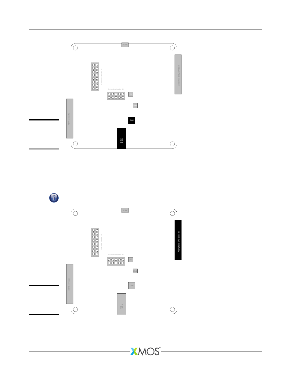
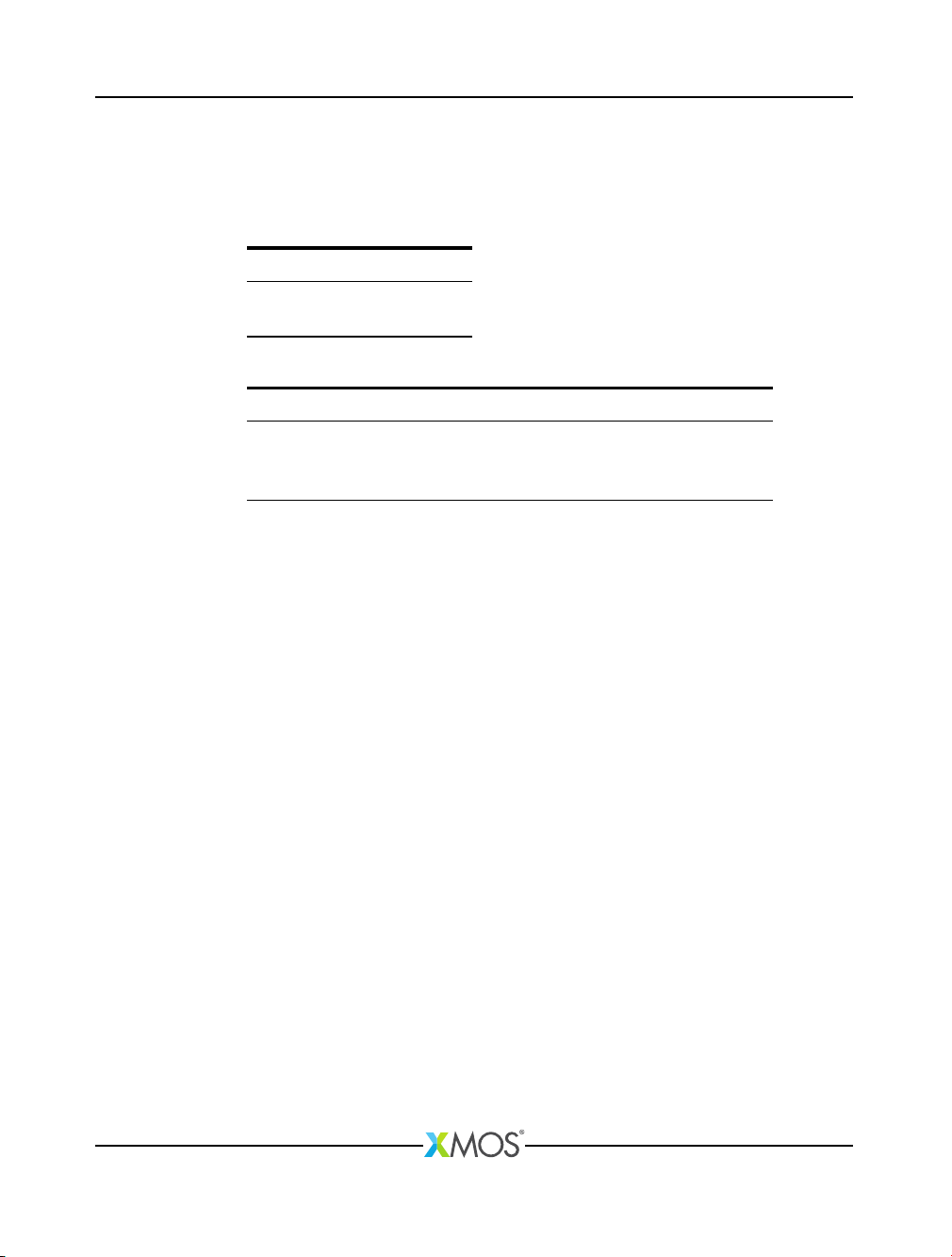
xCORE VocalFusion 4-Mic Kit for Amazon AVS
(XK-VF3000-L33-AVS) consists
of an xCORE VocalFusion BaseBoard (XP-VF3000-BASE, Figure 1) and a separate
linear microphone array (LINEAR MICROPHONE ARRAY E, Figure 2) using Infineon
IM69D1301MEMS microphones.
The VocalFusion BaseBoard is based on the XMOS XVF3000 device, running a
software which integrates the xCORE microphone capture and voice processing
library to provide: beamforming, acoustic echo cancellation, noise suppression,
de-reverberation and automatic gain control.
The XVF3000 device has 16 32-bit logical processing cores and integrates 2MBytes
Quad Serial Peripheral Interface (QSPI) flash in a TQ128 package.
For general information on the XVF3000 device see the xCORE-200 Architecture
Overview
2
. For device specific information on the XVF3000 device see the XVF3000
Datasheet3.
1http://www.infineon.com/microphones
2http://www.xmos.com/published/xcore-architecture
3http://www.xmos.com/published/xvf3000_3100-tq128-datasheet
XM011897A