XMOS xCORE VocalFusion User manual

Getting started with xCORE VocalFusion Speaker
IN THIS DOCUMENT
·Requirements
·xCORE VocalFusion Features
·Install xTIMEcomposer Tools
·Download the Firmware
·Build the Firmware
·Run the Firmware
·Evaluation Procedure
This document describes how to get started with the xCORE VocalFusion Speaker
evaluation system and firmware. You will be guided through setting up the system,
downloading the firmware and programming the board. It is assumed that you are
familiar with the XMOS xTIMEcomposer programming tools. Additional information
and documents are available at http://www.xmos.com/vfspeaker.
1 Requirements
To evaluate xCORE VocalFusion Speaker, the following hardware/software is re-
quired:
·xCORE VocalFusion Speaker baseboard version 1.11
Figure 1:
xCORE
VocalFusion
baseboard
1
Version 1.0 of the baseboard may be used for USB evaluation however the I
2
S hardware setup is different from the
instructions provided in this guide as J6 is not present
Publication Date: 2017/12/2 Document Number: XM011320A
XMOS © 2017, All Rights Reserved

Getting started with xCORE VocalFusion Speaker 2/22
·Microphone board - Linear or circular with ribbon cable
Figure 2:
C43
microphone
board
Figure 3:
L33
microphone
board
·xTAG
- connects to the xTIMEcomposer tools so you can load application binaries
onto the target board
Figure 4:
xTAG
·Two micro-USB cables
- one cable provides connection to the baseboard, the
other connects the xTAG debug adapter to a host computer
·xTIMEcomposer
- the development tools provide everything you need
to program, debug and simulate your applications; download free from
http://www.xmos.com/tools2
·XMOS VocalFusion firmware download
- (1.1.1 or later). Available from
http://www.xmos.com/vfspeaker.
·A host computer with two USB ports
- macOS and Windows are supported for
USB configurations. For I
2
S configurations an audio source with an I
2
S master
interface providing a 24.576MHz MCLK is also required
2Requires an xmos.com account
XM011320A

Getting started with xCORE VocalFusion Speaker 3/22
·A single amplified loudspeaker
- This should have no audio enhancement
functionality: any audio processing will seriously degrade AEC performance
·Internet connection
- required to register the tools before you can use them,
and to access firmware repositories from within xTIMEcomposer
Parameter control will also require a host system capable of compiling the control
utility vfctrl. Please see the VocalFusion Control Users Guide3for details.
3http://www.xmos.com/published/vocalfusion-control-users-guide
XM011320A

Getting started with xCORE VocalFusion Speaker 4/22
2xCORE VocalFusion Features
The following features are supported:
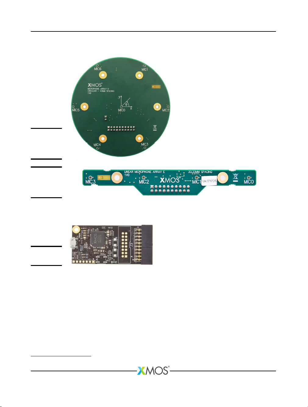
·Linear and circular/rectangular microphone array configurations
·4 microphone adaptive beamformer with 180 or 360 degree coverage options
·
Mono, full-duplex (barge-in) AEC with reference/far-end source from USB play-
back from host (also option of I2S)
·Stationary & diffuse noise suppression (tunable up to 15dB)
·De-reverberation
·
Control of microphone processing parameters via xSCOPE, USB or I2C (example
command line driven host application supplied)
·
16 or 48kHz host sample rate (processed microphone output is upsampled from
16kHz to 48kHz)
·Host connection via:
·
USB Audio Class 1.0 compliant device for AEC reference/far-end input and
processed mic output
·I2S mode for AEC reference/far-end input and processed mic output
·
Mixed mode using I
2
S for reference/far-end input and USB for processed mic
output
The processed output can be optimized for human communications (i.e. Internet
calls) or Automatic Speech Recognition (ASR) engines. The ASR output has less
processing applied which improves ASR performance but may subjectively sound
worse to a human.
Three main modes of operation for USB audio input to host are provided:
·1 channel: processed output is sent to the host (either ASR or communications
optimized)
·
2 channels: processed output is sent to the host on both channels (one optimized
for ASR, the other human communications)
·
6 channels: processed output, AEC reference/far-end and raw microphone data
are sent to the host
The first two configurations could be used in a deployment scenario. The primary
use of the third is for evaluation.
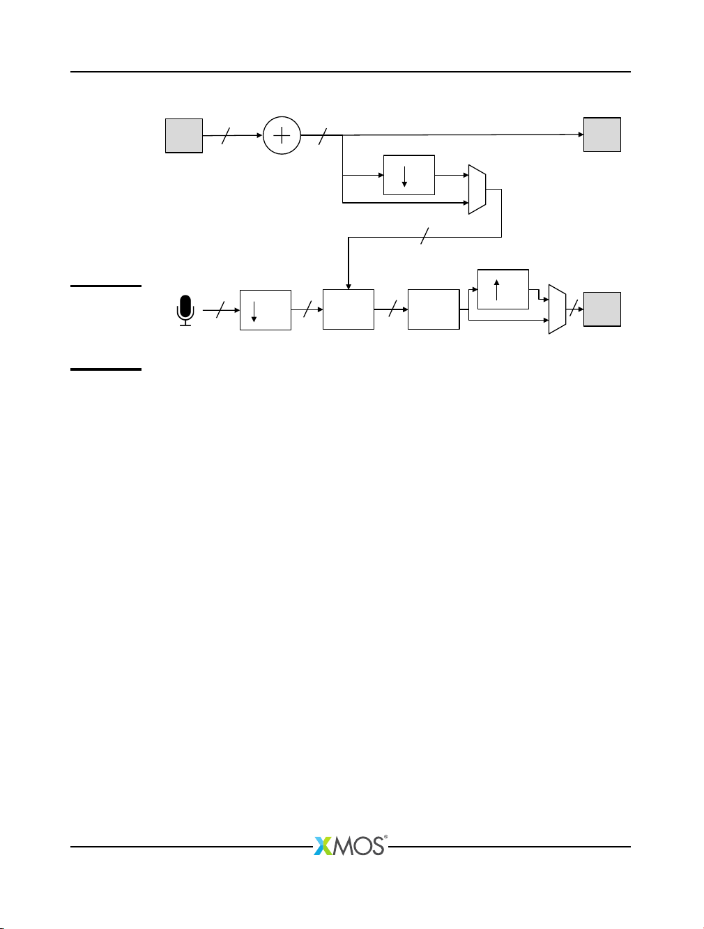
Figure 5shows the basic layout of the processing in xCORE VocalFusion. It shows
a stereo to mono down-mix, optional down-sampling and up-sampling as well as
the main Acoustic Echo Cancellation and Beamforming & Post-processing blocks.
XM011320A

Getting started with xCORE VocalFusion Speaker 5/22
Far-end
In
Far-end
Out
3
BAP
192 AEC
3
MIC
Out
4 4 1
2 1
4
3.072MHz
16KHz
16/48KHz
1
16KHz
16/48KHz 16/48KHz
AEC = Acoustic Echo Cancellation
BAP = Beamforming & post-processing
Mix
Down-sample
Down-sample
Up-sample
16KHz
Figure 5:
Block
diagram of
VocalFusion
Speaker
3 Install xTIMEcomposer Tools
xTIMEcomposer provides everything required for programming xCORE processors.
The tools are provided free of charge to users registered on the xmos.com
website. Versions are available for Windows, macOS and Linux platforms from
https://www.xmos.com/support/tools.
xCORE VocalFusion requires version 14.3.2, with a Java Runtime Environment (JRE)
version 1.6 or later installed. See the xTIMEcomposer download page for further
information on using xTIMEcomposer and Java requirements.
4 Download the Firmware
The xCORE VocalFusion firmware contains source-code that includes the voice
processing, control and I/O processing.
The firmware is provided as a single zip archive named sw_vocalfusion.
Download the firmware images from:
https://www.xmos.com/vfspeaker
5 Build the Firmware
You need to import the firmware source code into the tools, build it and then
execute it on the target board. Build either using the xTIMEcomposer IDE or from
the command line.
XM011320A

Getting started with xCORE VocalFusion Speaker 6/22
5.1 Build Firmware under xTIMEcomposer IDE
The following section details how to build the firmware and generate a binary.
5.1.1 Start xTIMEcomposer IDE
The first time you start xTIMEcomposer IDE you will be prompted for your MyXMOS
registration details, you will need to be connected to the Internet.
When xTIMEcomposer starts you will be prompted to specify the location of your
workspace. This is where your Eclipse workspace files will be kept and where the
firmware will be imported to. Once the workspace location has been set you will be
prompted with a project explorer window which will either contain your existing
Eclipse projects or be empty if you have setup a new workspace.
You may need to close the WHAT’S NEW in 14.0.0? RELEASE NOTES & COMPATIBIL-
ITY window by clicking the cross at on the tab at the top
5.1.2 Import the Firmware
To import the sw_vocalfusion firmware zip archive, follow these steps:
1/ Select File ·Import (Figure 6)
XM011320A

Getting started with xCORE VocalFusion Speaker 8/22
Figure 7:
Firmware
import type
3/ In
Select archive file
, click
Browse
and select the zip file you have just down-
loaded. When you have browsed to the downloaded archive and clicked
Open
, a
list of available modules and applications will be seen. They should all already be
selected so just click
OK
to import xCORE VocalFusion, if needed, and all of its
modules and libraries. (Figure 8)
4/ Click Finish to complete the import.
A dialogue will display a warning that some configurations exist in the project but
not in the makefile. If you intend to later import the TrulyHandsfree
TM
library and
build keyword enabled build configurations click “no” otherwise click “yes”.
XM011320A

Getting started with xCORE VocalFusion Speaker 9/22
Figure 8:
Firmware
import
selection
The projects should now appear in the Project Explorer window. (Figure 9)
5.1.3 Build the Firmware
To build the firmware, you need to select the desired build configuration, for
example 1i1o2_cir43, and set it as the current project, configure the build options
for make and then build the project.
Click on app_vf_spk_base in Project Manager and select
Project ·Build Configu-
rations ·Set Active. (Figure 10)
XM011320A

Getting started with xCORE VocalFusion Speaker 10/22
Figure 9:
Firmware
import
selection
Figure 10:
Selecting The
Active Build
Configura-
tion
With the desired configuration selected in the menu, click to set it as the active
build configuration.
Right-click on the project in the Project Explorer and select Build Project.
XM011320A

Getting started with xCORE VocalFusion Speaker 11/22
Expect build time of 2-3 minutes, depending on selected configuration. You will
note build warnings in the build. These do not affect functionality, and will be
removed in a future release of the firware.
Navigate to the
app_vf_spk_base ·bin ·1i1o2_cir43
folder in Project Explorer
where the compiled binary app_vfspk_base_1i1o2_cir43.xe has been generated.
(Figure 11)
Figure 11:
Compiled
binary in
Project
Explorer
5.2 Build from Command Line
First open an xTIMEcomposer command prompt. This will automatically setup the
required environment and paths to allow the compiler to run. Next navigate to the
following directory which can be found in the firmware package:
sw_vocalfusion/app_vf_spk_base
To build the firmware of your choice, you need to specify the desired configuration,
for example, 1i1o2_cir43. This is then passed via the
CONFIG
variable on the
command line. For example:
xmake CONFI G =1 i1o2 _cir 43
To see a list of supported build configurations type xmake allconfigs
Be sure to choose a build config that matches the microphone topology you are
XM011320A

Getting started with xCORE VocalFusion Speaker 13/22
6 Run the Firmware
The following section details how to run the compiled firmware binary.
6.1 Running from xTIMEComposer
To run the firmware you need to set up a Run Configuration for the xCORE Vocal-
Fusion project.
Click Run ·Run Configurations in the top menu bar. (Figure 12)
Figure 12:
Selecting Run
Configura-
tions
In the Run Configurations window, double-click xCORE Application.
If C/C++ Application is not auto-completed, click
Browse
and navigate to the
compiled binary in your project. For example:
app_vf_spk_base/bin/1i1o2_cir43/app_vf_spk_base_1i1o2_cir43.xe.
XM011320A

Getting started with xCORE VocalFusion Speaker 14/22
Your Run Configuration should now appear similar to the following (Figure 13):
Figure 13:
Run Configu-
ration
settings
Check that Target is set correctly, as shown in (Figure 13). If this is not the case,
ensure that the device is connected correctly and click on
Refresh list
. If this is
not enough, try to unplug and plug the xTAG adapter and use the
Refresh list
button again.
Click Apply to save the configuration.
Click
Run
to download the application to the xCORE VocalFusion board, and run it.
The board will now running the desired firmware.
6.1.1 Erase board
If the board is reset or power cycled, it will boot into any firmware programmed
in its flash. If firmware is ran rather than flashed, it is good practice to erase the
flash first. Should the board reset or power cycle after run, empty flash ensures it
will not run another version unexpectedly.
XM011320A

Getting started with xCORE VocalFusion Speaker 15/22
Figure 14:
Flash
configuration
for erase,
page 1
The erase command is listed in §6.2. An alternative to using the command line is
to create a pseudo flash configuration in xTIMEcomposer.
·
Select
Run ·Flash Configurations
(Figure 14). In Flash Configurations, double-
click xCORE Application.
·
Now select the application’s XN file for C/C++ Application; click
Browse
and
navigate to:
app_vf_spk_base/src/core/vfspk_base_usb.xn
·
Switch to
XFlash Options
tab (Figure 15), and enter the following in Other
XFlash Options:
--erase-all --target-file
·
Check that Target is set correctly. If this is not the case, ensure that the device is
connected correctly and click on Refresh list. If this is not enough, try to unplug
and plug the xTAG adapter and use the Refresh list button again.
·Click Apply to save the configuration.
XM011320A

Getting started with xCORE VocalFusion Speaker 17/22
6.2 Running from the Command Line
Optionally the XE file can be run on a target outside of the xTIMEComposer IDE.
From a xTIMEComposer command prompt, run the chosen XE file on the target
using the command:
xr un < fi le _n ame >. xe
Ensure that the relevant binary is run for the connected microphone configuration
(i.e. circular vs linear and spacing)
If the board is reset or power cycled, it will boot into any firmware programmed
in its flash. If using xrun rather than xflash to run firmware, it is good practice to
erase the flash first. Should the board reset or power cycle after xrun, empty flash
ensures it will not run another version unexpectedly:
xfla sh -- erase - all -- target - file a pp_ vf _s pk _b ase / src / core / vfs pk_ b ase _u sb . xn
XM011320A

Getting started with xCORE VocalFusion Speaker 18/22
7 Evaluation Procedure
The following section contains specific information about how to demonstrate
xCORE VocalFusion. Please jump to the relevant section that matches your audio
host connection:
·Full USB Configuration
·Full I2S Configuration
·USB with I2S AEC Reference
7.1 Full USB Configuration
The default configuration is fully USB based and allows evaluation of the key
xCORE VocalFusion features. It uses USB Audio Class 1.0 transport to stream the
microphone signal(s) to the host and playback the AEC reference/far-end signal
from the host to the on-board DAC. This evaluation will be using the following
build:
·1i2o2_lin33_48khz/1i2o2_cir43_48khz: 2 channel input, 2 channel output
This build has processed output for communications (optimized for human listen-
ing) on channel 0 and processed output for
ASR
(optimized for machine listening)
on channel 1.
7.1.1 Hardware Setup
Host
Host
VocalFusion
xTAG
USB
USB
Figure 16:
Connection
diagram (USB)
According to Figure 16:
·
Connect the xCORE VocalFusion Base Board to your computer using the micro-
USB cable provided
·
Connect the xTAG adapter to the xCORE VocalFusion Base Board via the xSYS
DEBUG connector
XM011320A

Getting started with xCORE VocalFusion Speaker 19/22
·
Use the second USB cable to connect the USB receptacle on the xTAG to a host
computer with xTIMEComposer installed
·
Connect the 3.5mm AUDIO OUT on the xCORE VocalFusion Base Board to an
amplified speaker - once again ensuring the speaker has no audio processing
enabled.
For best AEC performance ensure that the microphone board is protected from
vibrations resulting from the loudspeaker operation. Layer of suitable soft material
between the speaker and the microphone board will dampen vibrations.
For best performance the linear microphone array should be facing towards the
user(s)
7.1.2 Evaluation Procedure
You will play a sound track through loudspeaker into the room, speak or use
another loudspeaker as near-end speech, and record output of xCORE VocalFusion.
The output will have echo cancellation applied, beamforming and further postpro-
cessing such as echo suppression. It will leave the near-end speech sounding much
clearer than it would in the raw microphone recording.
·
Once successfully enumerated the device will appear as a USB Audio Device
named XMOS VocalFusion Spk (UAC1.0)
·
Select the new sound card as your computers default audio device. On a Mac
use Audio MIDI Setup or alt-click on the sound icon in the tool bar. In Windows
uses the sound preferences in Control Panel
·
It is best to allow the program to adjust to the acoustics of the room before
playing an AEC reference/far-end (typically 10 seconds of talking).
·
Play the AEC reference/far-end signal from any audio program (e.g. iTunes) to
the board - ensure it can be heard being played out of the speaker.
·
Use your favorite application (e.g. Audacity) to record from the device and
playback the results of the processed audio.
In both cases the AEC reference/far-end signal played to the device over USB is
down-mixed to mono and output to the right speaker only. Output to the left
speaker is muted.
7.1.3 Windows Specific
You can use any sound subsystem on Windows such as MME, DirectSound and
WASAPI. With WASAPI in Audacity, if you get no sound and level meters not moving,
check that the Audacity project sample rate matches the USB device’s sample rate.
Windows includes a USB Audio Class 1.0 driver to support the xCORE VocalFusion
device.
XM011320A

Getting started with xCORE VocalFusion Speaker 20/22
When a configured evaluation kit is connected to a Windows PC, the native driver is
installed and the device details are stored in Windows’ USB cache. If subsequently
a different version of the evaluation kit is connected (for example, an evaluation kit
with a firmware using the same VID and PID but exposing a different configuration
of audio channels) then the Windows’ USB cache is not updated and the USB audio
connection to the evaluation kit will not operate correctly.
If this occurs, typically when changing between 16kHz and 48kHz firmware con-
figurations, disconnect the evaluation kit and use the USBDeview utility (freeware
available from
http://www.nirsoft.net/utils/usb_devices_view.html
) to unin-
stall all instances of XMOS USB audio devices. Then re-connect the evaluation kit;
fresh instances of the UAC1 driver will then be correctly installed.
7.2 Full I2S Configuration
The device can optionally receive the AEC reference/far-end signal via I
2
S (slave/-
master) and also output the processed microphone output over I
2
S (slave/master).
The sample rate for the I
2
S interface can be either 48kHz or 16kHz. The host rate
of 48kHz is used in this example to allow high quality audio to be played back.
The below procedure uses following configurations:
·
1i0o0_lin33_i2s_only_48khz/1i0o0_cir43_i2s_only_48khz: 2 channel input, 1
channel output
Note that xCORE VocalFusion is I
2
S slave in these configurations, and will require
an external 24.576MHz master clock.
7.2.1 Hardware Setup
Embedded
Host
Host
VocalFusion
xTAG
I2S
USB
Figure 17:
Connection
diagram (I2S)
In order to demonstrate I
2
S being used for input and output put the AEC
reference/far-end signal and the processed microphone signal the following
modifications must be made to the xCORE VocalFusion board. According to
Figure 17:
XM011320A
Table of contents