Xo XOUIM1565O User manual

I worked really hard
on this manual -
so please read it...
XOUIM1565S & XOUIM1565SP
XOUIM1565O & XOUIM1565OP
UNDERCOUNTER GOURMET ICE MAKER

2
UNDERCOUNTER
When buying any XO appliance
you can be confident you have chosen a
high quality, innovative and stylish product
from a company that cares about you!
If you require service or have questions,
Help is only a phone call away -
call: 973-403-8900
Talk to one of our undercounter experts.
CONGRATULATIONS
on purchasing your XO.
Before you proceed, take just
a moment to register your XO at:
Ensuring warranty coverage should you need service
Providing ownership verification for insurance purposes
Let’s XO notify you in the event of product changes or recalls.
www.xoappliance.com/register-your-product/
REGISTRATION HELPS YOU BY -

Before You Get Started
Safety Instructions
Electrical and Grounding Instructions
Care and Cleaning
Stainless Steel
Interior Washing
Cleaning
Sanitization
Maintenance Schedule
Winterizing
Trouble Shooting
Before You Call For Service
Warranty
4 - 7
Installation Instructions
S
Plumbing
With & Without Drain Pump
Reversing the Door
Door panel Installation
Outdoor Use
izes and Installation Dimensions
8 - 23
27 - 35
36 - 38
3
where things are
please read and follow
all safety instructions
It’s for your
own good...
Honest.
Installer Checklist
Find Your Model
Operating Instructions 24
- 26
Features & Specifications
Operating Instructions

4
heres’s ten steps for a quick & easy install
RISK OF CHILD ENTRAPMENT!
An empty refrigerator is a very dangerous attraction to children.
Remove door gaskets, latches, lids, lock and/or doors from unused or discarded appliances,
or take other actions to guarantee them harmless.
Always dispose of old appliances in accordance with local laws and regulations.
Inspect cabinet opening for water, drain and electrical connections.
The 1/4” O.D. water supply line must include isolation valve and should include an inline water
filter (consult manual). Do NOT use a self-piecing valve for the supply connection. Water
supply must have a minimum pressure of 20 psi and a maximum of 80 psi. Cold water
should be between 50 F and 90 F - NOTE: warmer water will slow ice production.
is strongly recommended.
Drain tubing will be 5/8” ID gravity fed or 3/8” ID for a pump model. All horizontal drain
runs must drop 1/4” per foot. The drain should include an air gap device to prevent
siphoning and a sanitary trap. A restricted or inadequite drain can result in poor ice
production and possible flooding.
Electrical requirement is 15a dedicated, grounded circuit - outdoor installs must use a GFI.
Route water supply tubing to the water inlet located at the rear of the unit.
Connect the drain tubing to either the pump discharge or the barbed gravity fed elbow.
Be sure nothing is kinked, and excess slack is removed.
Be sure the electrical connection is secure into the wall outlet.
Slide the machine into location or cavity being careful not to allow for any kinks to occur
in the water inlet and drain tubing.
Adjust the Ice Maker to level using the leg levelers.
Add approximately 2-3 quarts of water to the bin and make certain it is draining properly
and check for leaks. If water does not drain, stop and verify tubing is not restricted.
Wash down the interior of the machine with a mild detergent solution (consult manual)
Turn the machine on and allow it to make ice for approximately 30-35 minutes to verify
ice is being produced and water is draining freely. Be sure to check the cube size, shape
and clarity. Discard the first batch of ice.
adjust if needed.
Always do one last check to be sure all water and drain connections are leak free.
1
2
3
4
5
6
7
8
9
10
oo

5
GOURMET ICE MAKER
STAINLESS STEEL
XOUIM1565S & XOUIM1565SP
PANEL READY
XOUIM1565O & XOUIM156OP
2
these are the models
covered in this
book
take a minute to circle your model above
and record your serial number
here in case you need it later
INDOOR / OUTDOOR

Please read through completely before using your XO Unit
Periodic maintenance is essential for safe operation - the unit must be easily pulled out for full access.
The appliance must be positioned so that the plug and water shutoff are readily accessible.
Empty your XO unit before attempting to move the appliance. Moving while loaded may damage or
distort the frame.
The compressor will get HOT during operation / touching it may cause injury.
During installation follow all safety tips provided in this manual / appropriate safety equipment such as
safety glasses and work gloves should be worn.
Two people should move or lift your XO unit to prevent injury or damage.
Remove all interior and exterior packing materials prior to installation and dispose of properly.
Always use only approved cleaning and descaling products to maintain your XO Ice Maker.
For maximum efficiency, keep the door tightly shut unless removing ice.
Before installing, allow your XO unit to sit upright for 2 hours at the install site. This will allow the cooling
system to stabilize after transportation. Failure to follow this step may cause problems.
Location
Your XO unit should be located away from direct sunlight and heat sources (stove, heaters, etc.) which may
increase electrical consumption. High or low ambient temperature may cause units to work improperly.
Optimal operation occurs in the ambient temperatures of 50 - 68 F and water temperature below 50 .
The floor must be strong enough to support your XO unit fully loaded.
Your XO unit must not be installed in areas of where water or e
xcessive moisture are present.
Your XO unit’s final installation must observe the correct minimum air clearances around and behind the
unit to ensure adequate ventilation. In addition, all ventilation openings must be kept clear and free of
obstructions, failure to do so will result in damage to the unit.
WARNING
NEVER use external heat sources to accelerate defrosting
NEVER permit unauthorized service or modifications to your XO unit
NEVER tamper with the sealed refrigerant system - this unit uses R134a Refrigerant.
It should never be used in the vicinity of any flammable or explosive ignition sources.
ALWAYS FOLLOW THE ELECTRICAL SAFETY INSTRUCTIONS OUTLINED IN THIS MANUAL.
6
your safety matters
Never store bottles, cans or perishable food products such as meat or cheese in your XO Ice Maker.
Your XO unit must not be installed near
where flammable, corrosive or hazardous materials are present.

Failure To Follow All Electrical Safety Measures May Result in Serious Injury,
Fire Or Death
All electrical work should only be performed by an
experienced, licensed electrician.
All XO units MUST be grounded for safe operation and
come equipped with a
3 Prong molded cord/plug for that
purpose.
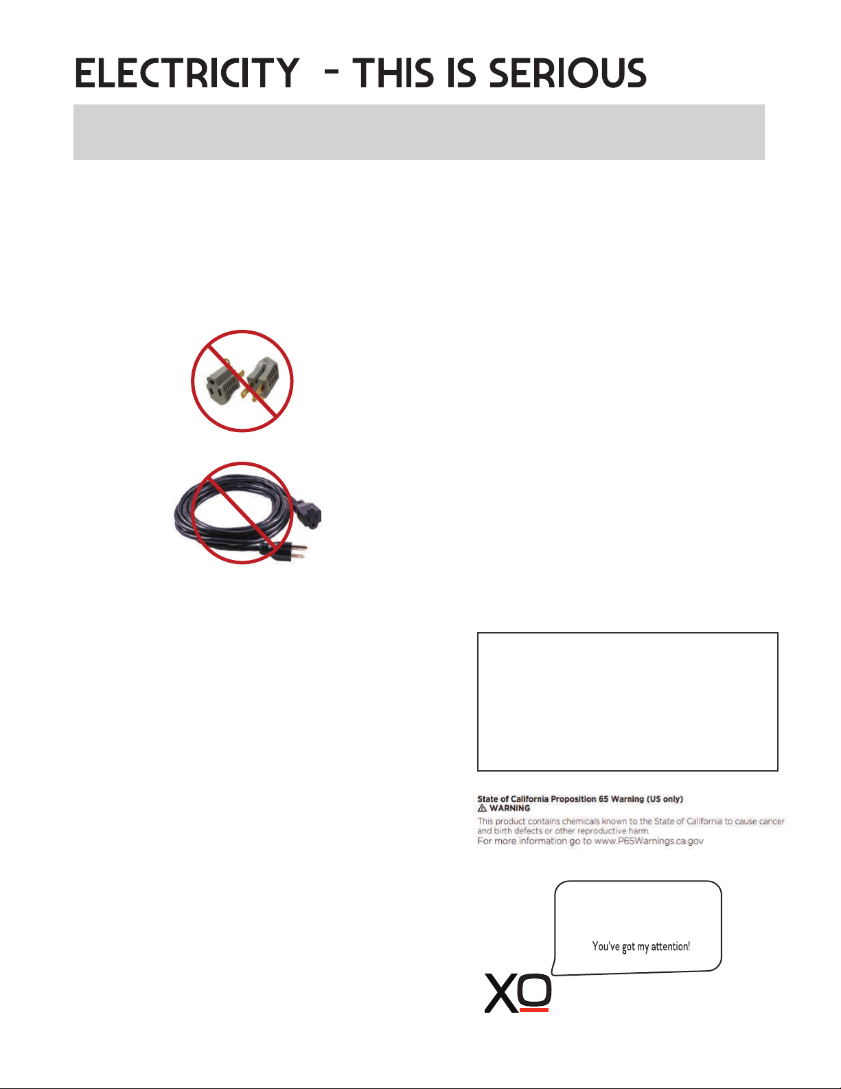
NEVER remove or disable the 3rd prong with an adapter.
NEVER use an extension cord to operate your XO unit.
Your XO unit is built to operate on 115V 60Hz and
should be plugged directly into a dedicated 15 amp
3 prong outlet. If you are uncertain as to the
voltage, amperage capacity or if the 3rd prong is
properly grounded - consult a licensed electrician.
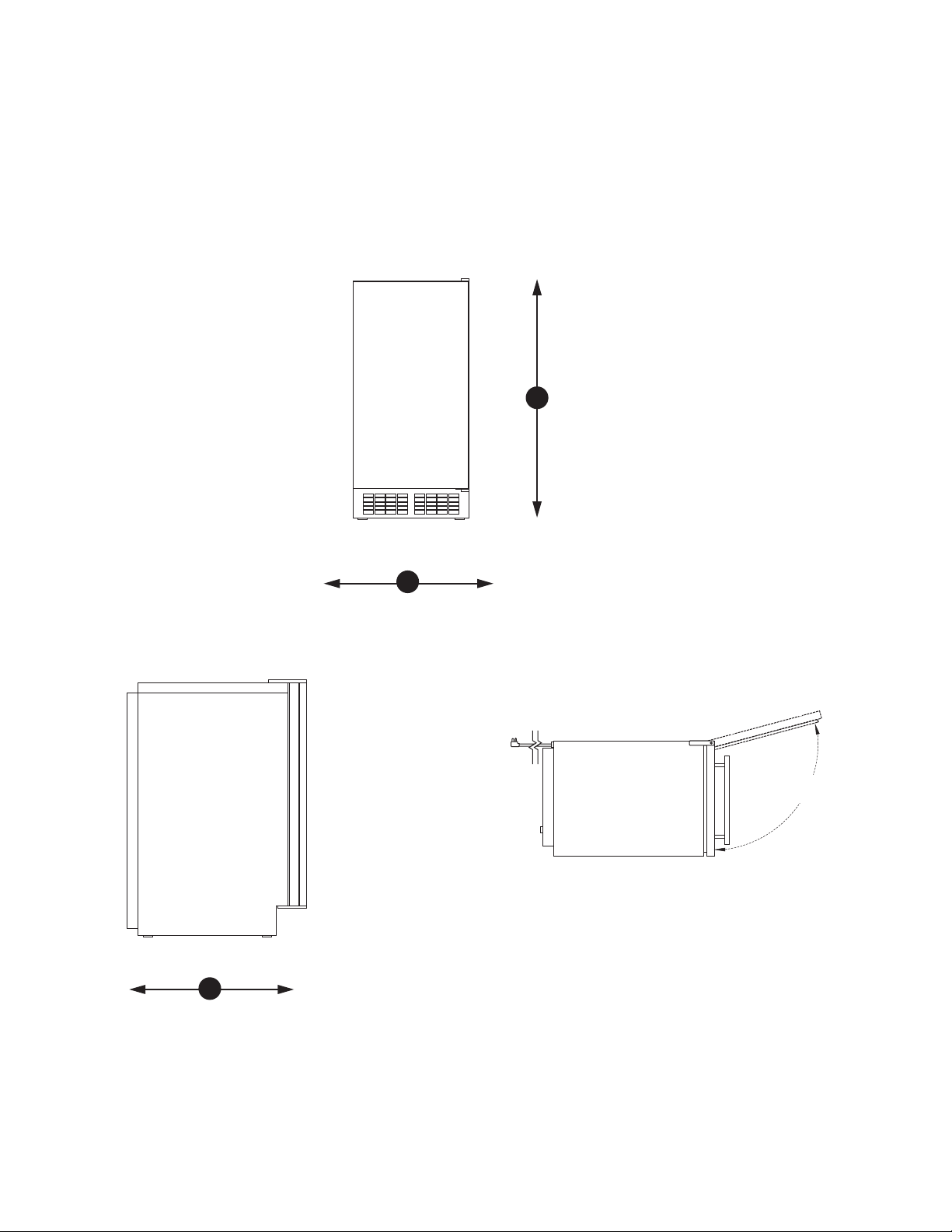
To maximize the depth of the installation recess -
your outlet should be mounted flush with the wall.
Your XO unit should not share the circuit with any other
electrical devices as this may cause overloading,
overheating, blown fuses or tripping circuit breakers.
In a worst case this can pose a fire hazard.
NEVER handle your XO unit in wet conditions as this
can pose a severe danger of electric shock.
Exercise care when moving your XO unit to avoid
damage to the electrical cord. If the electrical cord of
your XO unit becomes worn or damaged it must be
replaced immediately by a qualified technician.
NEVER unplug your unit by pulling on the cord.
Unplug by gripping the plug firmly and pull out
straight from the outlet.
FOR INDOOR OR OUTDOOR USE:
XO Ice Makers shown in this manual are rated for
Indoor and Outdoor use.
These units are designed to operate in ambient
temperatures between 50 and 90 F.
Avoid installing the unit where it may be exposed to
heat or direct sun, dusty or damp conditions or in a
location where it may be rained on or splashed by
water.
Never install the unit where flammable or corrosive
chemicals (such as pool chemicals) are present.
Installation in seaside environments where high
concentrations of salt are present will require more
frequent cleaning to avoid corrosion.
Use in any uncontrolled area or otherwise exposed
to the elements is hazardous and voids the warranty.
In regions where high humidity exists (greater than 70%)
condensation may appear on the door and/or door
gaskets. This is normal and will disappear as humidity
drops.
SERVICE 115V - 60 Hz - 1 phase
AMPS 15 Amp Circuit Breaker
Requires a Dedicated Outlet
GFI required for Outdoor Installations
All electrical work must be performed by
a licensed electrician
7
Serious injury, fire or death...
Okay -
o o

8
a perfect fit
install under counter
When installing, remember you need
to leave ready access to both the power
Cut access to an adjoining cabinet to
locate outlet and water there.
ALL XO UNDERCOUNTER
UNITS ARRIVE PRE-WIRED
WITH LOW PROFILE PLUGS
FOR EASY INSTALLATION
4"
(100mm)
7"
(178mm)
34” MINIMUM
(864mm)
15”
WHEN INSTALLING WITH
THE HINGE SIDE NEXT TO A WALL -
LEAVE ADEQUATE SPACE FOR
YOUR DOOR HANDLE
90°
Door Swing
WALL
Clearance
Gap
(381mm)
MINIMUM

9
a perfect fit
your xo is this big ( or small, as the case would be )
XOUIM1565G & XOUIM1565GP ICE MAKER
33-
HIGH
(857mm)
3/4”
W
H
height & width
depth
23-3/8”
(594mm)
D
THE OVERALL DEPTH SHOWN (22-5/8”) INCLUDES THE DOOR WITH 3/4” PANEL.
THE DEPTH OF THE ICE MAKER CABINET ONLY IS 21-3/16”
14-7/8” WIDE
(378mm)
TOP VIEW
105 º

10
before you install
check a few things
115V~60Hz
e
Is the installation location COOL, DRY, LEVEL and away from direct sun.
The water supply valve must provide positive shut off capability and be readily accessible.
Does the unit have a dedicated 115V three prong grounded outlet? (use GFI outdoors)
The Cold Water supply is 1/4” O.D. tube, it should be 50 to 90 F and be between 20 and 80 psi.
(NOTE: as the inlet water temperature increases - production efficiency goes down.)
YOU WILL NEED -
A few simple hand tools:
Pump pliers, adjustable wrench, #2 Phillips head screwdriver, level, razor knife
AND a few hardware items:
Teflon tape or Pipe dope
5/8” I.D. drain hose and hose clamps (if installing a gravity drain model)
1/4” O.D. water supply hose
Air Gap Device and/or Sanitary Trap (depending on your installation).
Water filter with isolation valve
Depending on your installation you will probably require additional site specific plumbing fittings
Water source valve
Water source tub
Drain hose
o o

11
All water contains some impurities and minerals.
Your XO Ice Maker is designed to produce crystal clear, gourmet ice. It does this by
reducing the mineral content in the water as the ice is forming.
PURER WATER YIELDS PURER ICE.
Cubes are formed by cold water spraying against a chilled mold. Pure water freezes faster
than water containing impurities. The spraying action causes the cubes to be built up in layers
as the pure water freezes more quickly and the water containing impurities is washed away by
the spray and falls into the water bin to be diluted and drained away.
When the ice maker senses the cubes are fully formed and ready, the ice cube molds are
heated slightly causing them to drop out of the mold and into the ice holding bin.
Periodic maintenance is required to ensure that your ice maker is performing at its best.
See the maintenance section of this book and the Maintenance Schedule.
FILTERS AND WATER TREAMENT
The correct filter is always recommended. It has the ability to remove odors as well as
particulate from water prior to reaching the ice maker.
(consult www.xoappliance.com for more information on which filter is right for you)
Water softeners exchange one mineral for another (salt) which can cause inferior ice quality
such as soft, mushy ice that clumps together. If you are using a water softener, you should
install a bypass to supply untreated water to the ice maker.
Water produced by Reverse Osmosis and deionized water are not recommended. It is more
corrosive than tap water and can cause harm to the equipment over time.
water quality

12
Plan the arrangement of the water supply pipes. You will need both a water supply line and
a drain (see section on installing a gravity drain unit or pump drain unit)
If the tap water has a high level of minerals, an inline filter will be required.
Attach the water supply line to the rear of the unit
with flexible tube to the fitting indicated here.
The tubing must be long enough to permit the
unit to be pulled out for service.
Water supply should be between 20psi and 80psi.
Attach the drain to the connection indicated here
If you are installing an XOUIM1565S unit with a
gravity drain, the line must be pitched down
1/4” per ft to ensure correct drainage.
If the drain is positioned at a higher elevation than
the connection on the rear of the unit, a pump
will be required. Use model XOUIM1565GP.
This unit comes with a pre-installed drain pump
capable on discharging to a drain up to 8’ above
the unit.
IMPORTANT: The keep drains as short and straight
as possible for optimal performance.
The electric power, water supply pipeline and drain pipeline must be in compliance with all
provisions under the local laws and building regulations.
IMPORTANT: The product is designed for use in a fixed condition but it may be required to
pull the product out for service. Therefore, do not install any material at the front, upper or
lower end of the product which may be an obstacle when pulling the product out.
Once the unit is in place, use the leveling legs to ensure the unit is level.
Each side should have at least 1/16" of space for projection of the screw head near the bottom.
the plumbing
REAR
VIEW
ELECTRICAL CORD
DRAIN
WATER
SUPPLY
1/4” O.D.

13
INSTALLING THE XOUIM1565S without a drain pump.
Position the ice maker in front of the opening. Level the unit using the leveling legs.
Wash and flush the water supply tube and connect the unit to the cold water isolation valve.
Prepare the drain. The drain must be pitched downward at a drop of 1/4” per foot to drain properly.
Horizontal runs of 5’ or more must be anchored to a wall for support to prevent sagging.
A sanitary trap and air gap must be installed in the line prior to entering the home’s drain system.
The trap prevents sewer gas from flowing back to the ice maker.
The air gap device prevents siphoning drain water back into the ice maker.
Cut the 5/8” ID drain hose (not supplied) to the required length. Immerse the hose in warm water to make
installation easie
hose to the drain using hose clamps.
r, then using a threaded hose barb connection sealed with teflon tape, connect the drain
Turn the water supply on and check to ensure there are no leaks.
If there are no leaks, plug the unit into the electrical outlet.
Press the switch to the “ICE” position. The compressor will run approximately 3 - 5 minutes.
Slide the unit back into it’s final position and recheck to ensure it is level.
REMEMBER to adhere to all local building codes and regulations
with gravity drain
DRAIN VENT
THE DRAIN POINT
MUST BE LOWER
THAN THE DRAIN
OUTLET OF THE
ICE MAKER
AI
DEVICE
R GAP
SANITARY TRAP
If you purchase a gravity drain unit
and find you need one with a pump
the XOUIM1565S can easily be
retrofitted with one in the field.
Simply order a XOUIMPUMP from
www.xoappliance.com

14
INSTALLING THE XOUIM1565SP with DRAIN PUMP.
Position the ice maker in front of the opening.
Level the unit using the leveling legs.
Wash and flush the water supply tube and connect the unit to the cold water isolation valve.
Cut the 3/8” diameter drain hose to the required length. Immerse the hose in warm water to make
installation easie
(9’ of 3/8” ID drain hose is included with pump models)
r, then connect the drain hose to the drain using hose clamps.
IMPORTANT: Check local codes to determine if an air gap is required between the drain and the pump.
Turn the water supply on and check to ensure there are no leaks.
If there are no leaks, plug the unit into the electrical outlet.
Fill the ice container with clean tap water approximately 3/4 full. The drain pump should turn on and pump
the water out. Check again for leakage.
Press the switch to the “ICE” position. The compressor will run approximately 3 - 5 minutes.
Fill the ice container to 3/4 full once more. Block the drain tube while the pump is running.
The pump should continue to run.
Slide the unit back into it’s final position and re-check to ensure it is level.
REMEMBER to adhere to all local building codes and regulations
with drain pump
DRAIN VENT
THE DRAIN POINT
MAY BE HIGHER
THAN THE DRAIN
OUTLET OF THE
ICE MAKER
SANITARY TRAP
AIR GAP DEVICE

reversing the door
Your XO Ice Maker is shipped with the hinge on the right hand side but it can be easily reversed.
IMPORTANT NOTE: Stainless Steel door models and Panel Ready models use different hinges
and Panel Ready models require additional steps when reversing the door.
1. While supporting the door, remove the two (2) screws
(shown in RED) that hold the Top Hinge in place.
The Top Hinges are virtually the same for
Stainless Steel and Panel Ready models.
Remove the door by lifting it straight up.
2. Remove the two (2) screws that hold the Bottom Hinge in
place. Remove the two (2) corresponding screws on the left
hand side. Install the Bottom Hinge in the left hand position
and install the remaining two (2) screws into the holes on the
r
NOTE: The Panel Ready unit has an additional screw that
comes up from the bottom that must be also be removed.
In addition, you must reverse the DOOR STOP INSERT
shown in Step 2A before re-installing.
ight hand side.
.
TOP HINGE
RIGHT HAND
POSITION
LEFT HAND
POSITION
15
BOTTOM HINGE
RIGHT HAND
POSITION
LEFT HAND
POSITION
2A.
on the left side, you must reverse the DOOR STOP INSERT located
on the underside of the bottom hinge. Simply remove the hex head
bolt that doubles as the hinge pin (shown in BLUE) -
flip the stop over (shown in RED)
and re-install the hex head bolt.
Panel Ready Units Only: Before re-installing the bottom hinge
VIEWS OF
BOTTOM HINGE
SEEN FROM BELOW
BEFORE AND AFTER
REVERSING THE STOP

16
reversing the door cont.
3. At the rear of the unit, there are three (3) screws
along the top. Remove these screws.
On the top front of the unit, there is one (1) additional
screw on the left hand side, remove this screw.
The Top Cover plate will now lift off.
.
REAR OF UNIT
TOP COVER
4. Remove the Top Hinge Support which is held in
place by one (1) screw from the right hand side and
transfer it to the left hand side re-attaching it with the
screw.
Replace the Top Cover plate using the three (3)
screws along the rear of the unit. The screw removed
from the top front on the left hand side - must be screwed
i
Remove the plugs from the left hand side screw holes
on the top cover and door and move them to the right
hand side.
nto the corrosponding hole on the right hand side.
TOP HINGE
SUPPORT
Panel Ready Units Skip to Step 5A
5. Center the hole in the bottom left hand side of the door on the bottom hinge pin and slide the door
down into place. Install the top hinge using the two screws removed in Step 1.
5A. Panel Ready Units Only:
Turn the door so the bottom edge is facing up.
a Remove the DOOR STOP (shown in RED)
b Remove the ANGLE BRACKET (shown in Black)
c Flip the ANGLE BRACKET over and install
using one screw at the other side of the door.
d Replace the DOOR STOP with the mirror image
door stop supplied with the unit using the screws
removed earlier.
Pop the small plastic bushing out and replace it after
the panel is installed. SKIP TO STEP 2 ON PAGE 20
a
b
c
d

AFTER INSTALLTION UNDER COUNTER, OVERLAY DOOR MUST BE ABLE TO OPEN 90 .
o
overlay panel dimensions xouim1565o & xouim1565op
29 3/8”
MIN.
14 3/4"
FRONT
The panel has a minimum height of 29 3/8” - If making the panel 29 3/8” tall
no further adjustments are needed.
If the panel is taller than 29 3/8”
proceed to pages 18 and 19,
a notch or recess is required.
TOP
MAXIMUM PANEL THICKNESS 3/4”
PANEL MAXIMUM WEIGHT: 20 lbs.
17
3/4"
WATCH THE INSTALLATION
VIDEO ON OUR CHANNEL
https://www.youtube.com/channel/UCT-Ip-dM9hoPydpxZfrZzRA
www.xoappliance.com

AFTER INSTALLTION UNDER COUNTER, OVERLAY DOOR MUST BE ABLE TO OPEN 90 .
o
overlay panel dimensions xouim1565o & xouim1565op
14 3/4"
FRONT
3/4"
A
B
5/8"
NOTCH HEIGHT
30” DOOR
DETAIL A
30 1/8"
14 5/8"
3/4"
A
B
5/8"
9/16"
DETAIL A
SCALE 1 : 1
1"
DETAIL B
BACK
Door panels taller than 29 3/8” require a notch
as seen in Detail A & B on the hinge side.
If making the panel 29 3/8”, no notch (detail A,B)
is required.
The bottom of the notch should always be 29 3/8”
from the bottom of the panel.
To get the exact measurement subtract 29 3/8“
from the panel height.
EXAMPLES:
PANEL HEIGHT NOTCH HEIGHT
30” 5/8”
30 1/4” 7/8”
TOP
TOP
MAXIMUM PANEL THICKNESS 3/4”
PANEL MAXIMUM WEIGHT: 20 lbs.
18
DOORS
TALLER THAN
29 3/8”
5/8"
NOTCH HEIGHT
30 1/4” DOOR
30 1/8"
14 5/8"
3/4"
A
B
5/8"
9/16"
DETAIL A
SCALE 1 : 1
1"
5/8” 7/8”

MAXIMUM PANEL THICKNESS 3/4”
PANEL MAXIMUM WEIGHT: 20 lbs.
19
AFTER INSTALLTION UNDER COUNTER, OVERLAY DOOR MUST BE ABLE TO OPEN 90 .
o
overlay
handling handleless doors:
panel dimensions xouim1565o & xouim1565op
Handleless doors have a profile similar to that shown
Instead of a notch, if the design of the door will allow, a recess can be cut out with a router
to accommodate the hinge extension.
The bottom of the recess must be 29 1/4” up from the bottom of the door and 5/8” high -
the door, at the deepest point of the finger groove, must be at least 30” from the bottom
of the door.
5/8”
5/8”
1”
SIDE VIEW REAR VIEW
29 1/4”
TO BOTTOM
OF DOOR

installing the overlay panel
Installing the overlay panel is easy if you folllow these simple steps.
You will need the following tools:
A drill with 3/16” and 5/16” bits - and a #2 Phillipshead screwdriver
1.
2. Place the door face down on a flat surface and
remove the door gasket from the groove (shown in RED)
gently starting at one corner. Lay it flat in a safe place,
you will be replacing it shortly.
In the four (4) corners of the groove, you will see four (4)
holes. These are for screws that will assist in securing the
panel.
3. Before proceeding, attach the handle (if used) to your overlay door panel in the desired position
remembering to countersink the screw heads so they do not prevent the overlay panel from laying
flat against the door.
4. Attach the BLACK support plate to the bottom of the door using the three (3) screws (shown on RED).
.
While supporting the door, remove the two (2) screws
(shown in RED) that hold the Top Hinge in place.
Then remove the door by lifting it straight up.
TOP HINGE
REMOVED
+ + ++ ++ ++
BOTTOM OF DOOR
20
This manual suits for next models
3
Table of contents
Other Xo Ice Maker manuals