XONOX CT 200 User manual

X O N O X
T e c h n o l o g y G m b H / / 3 5 6 2 5 H u e t t e n b e r g / / G e r m a n y
P h o n e + 4 6 6 4 4 1 9 6 3 6 4 0 / / F a x + 4 9 6 4 4 1 9 6 3 6 4 1 0 / / . x o n o x - t e c . c o m
Operating Manual
XONOX CT 200

X O N O X
T e c h n o l o g y G m b H / / 3 5 6 2 5 H u e t t e n b e r g / / G e r m a n y
P h o n e + 4 6 6 4 4 1 9 6 3 6 4 0 / / F a x + 4 9 6 4 4 1 9 6 3 6 4 1 0 / / . x o n o x - t e c . c o m

Operating Manual CT 200
X O N O X
T e c h n o l o g y G m b H / / 3 5 6 2 5 H u e t t e n b e r g / / G e r m a n y
P h o n e + 4 6 6 4 4 1 9 6 3 6 4 0 / / F a x + 4 9 6 4 4 1 9 6 3 6 4 1 0 / / . x o n o x - t e c . c o m
Page 3 of 14
Content
1.
General ........................................................................................................................ 4
1.1.
General instructions .................................................................................................................................. 4
1.2.
Scope of supply ......................................................................................................................................... 4
2.
Product description ....................................................................................................... 5
2.1.
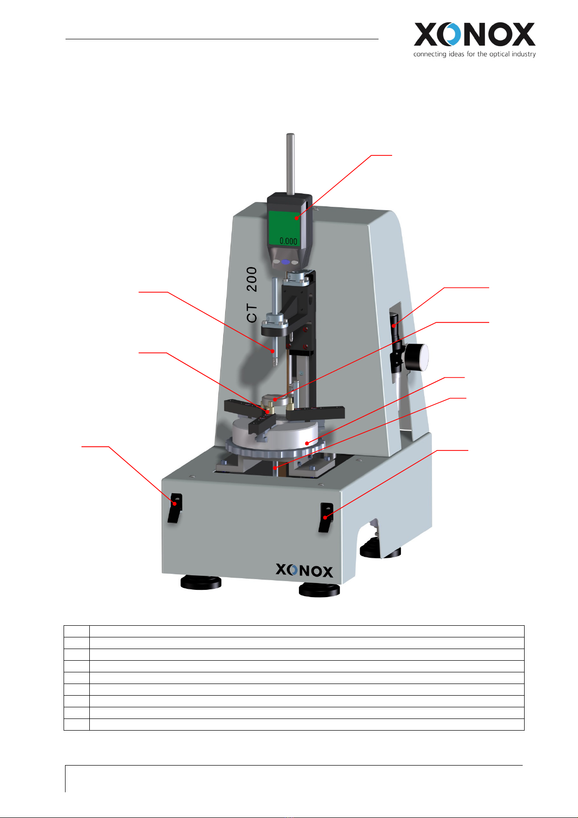
Configuration ............................................................................................................................................ 5
2.2.
Operation elements .................................................................................................................................. 6
3.
Installation ................................................................................................................... 7
3.1.
Adjustment ................................................................................................................................................ 7
3.1.1.
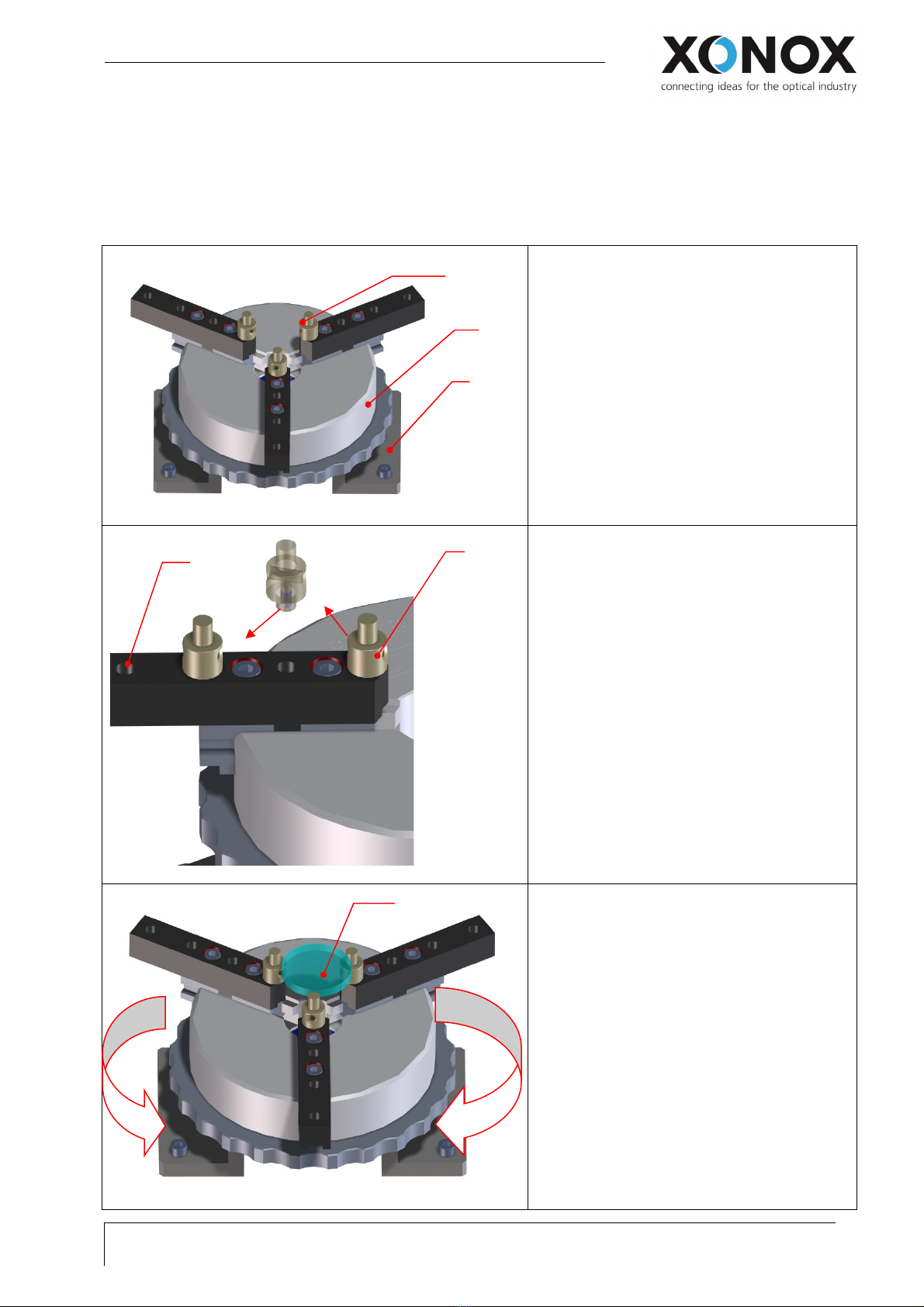
Adjustment of the Lenses...................................................................................................................... 7
3.1.2.
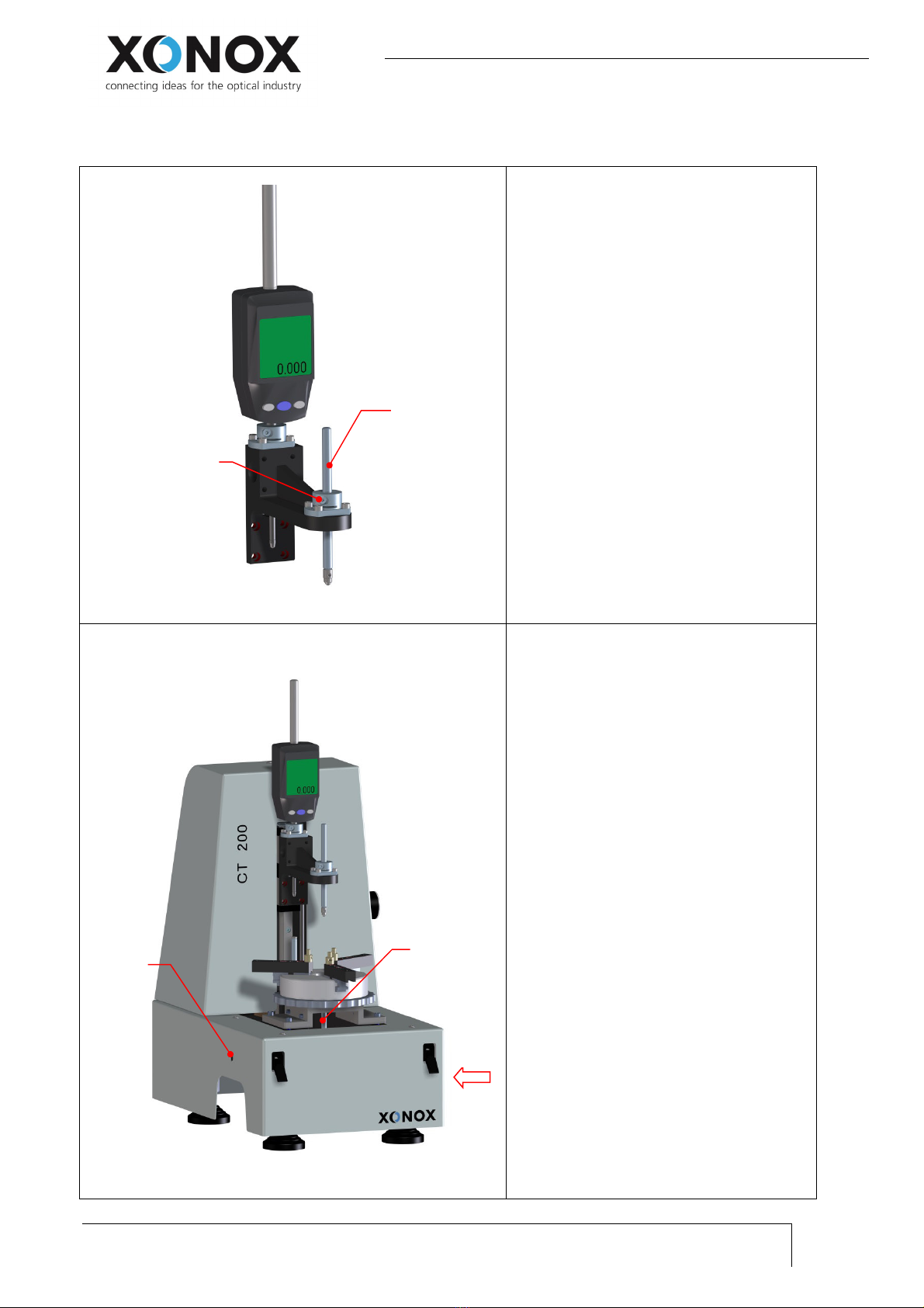
Adjustment of the upper and lo er measuring key button ................................................................. 8
3.2.
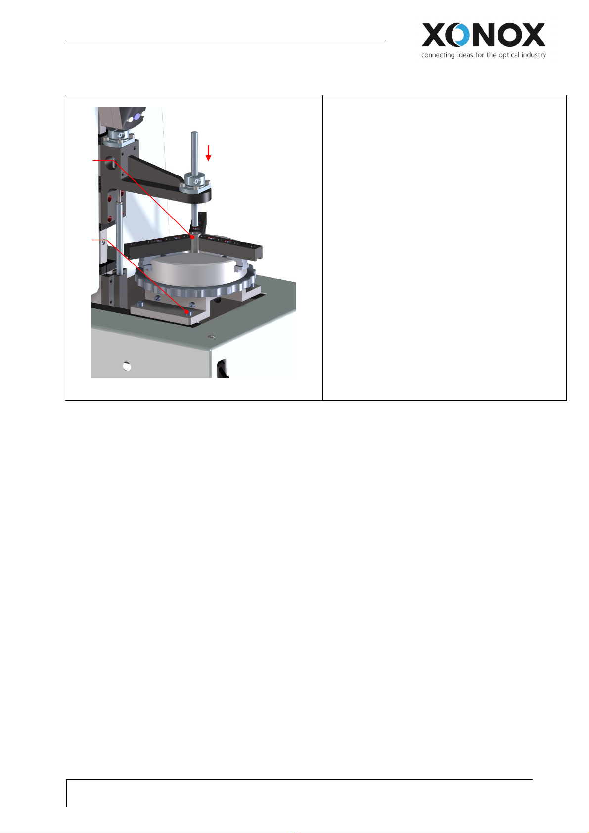
Alignment .................................................................................................................................................. 9
4.
Safety Instructions ...................................................................................................... 10
4.1.
General safety instructions ..................................................................................................................... 10
5.
Function and measurement ........................................................................................ 11
5.1.
Function of the measuring gauge ............................................................................................................ 11
5.2.
Calibration ............................................................................................................................................... 11
5.3.
Measuring procedure .............................................................................................................................. 12
5.4. Using the probe tips 12
6.
ppendix .................................................................................................................... 13
6.1.
Technical Data ......................................................................................................................................... 13
6.2.
Pneumatic plan ....................................................................................................................................... 14

Operating Manual CT 200
General
Page 4 of 14
X O N O X T e c h n o l o g y G m b H / / 3 5 6 2 5 H u e t t e n b e r g / / G e r m a n y
P h o n e + 4 6 6 4 4 1 9 6 3 6 4 0 / / F a x + 4 9 6 4 4 1 9 6 3 6 4 1 0 / / . x o n o x - t e c . c o m
1. General
1.1. General instructions
Dear Customer,
always keep the instruction manual near to the XO OX CT 200.
Only qualified people are allowed to use the XO OX CT 200.
1.2. Scope of supply
The scope of supply consists of:
-
- XO OX CT 200
- 3x lens support tips short
-
- 3x lens support tips long
- Respective holder
- Gauge block 10mm
- Probe tips 1x steel plan, 2x PEEK 5mm, 2x PEEK 3mm
- Alignment bushing
- Combination pliers
- Allen key 3mm
- Mitutoyo digital gauge 543-564D + remote control

Operating Manual CT 200
Product description
X O N O X
T e c h n o l o g y G m b H / / 3 5 6 2 5 H u e t t e n b e r g / / G e r m a n y
P h o n e + 4 6 6 4 4 1 9 6 3 6 4 0 / / F a x + 4 9 6 4 4 1 9 6 3 6 4 1 0 / / . x o n o x - t e c . c o m
Page 5 of 14
2. Product description
2.1. Configuration
Illustration 1: XONOX CT 200 exposition with inscription
1 Mitutoyo digital gauge 543-564D
2 Input valve (pneumatic)
3 Respective holder + gauge block 10mm
4 Lower probe
5 Manual chuck
6 Switch lower probe UP/DOW
7 Switch upper probe UP/DOW
8 Holding adapter for lenses
9 Upper probe
1
5
9
8
7
6
2
4
3

Operating Manual CT 200
Product description
Page 6 of 14
X O N O X T e c h n o l o g y G m b H / / 3 5 6 2 5 H u e t t e n b e r g / / G e r m a n y
P h o n e + 4 6 6 4 4 1 9 6 3 6 4 0 / / F a x + 4 9 6 4 4 1 9 6 3 6 4 1 0 / / . x o n o x - t e c . c o m
2.2. Operation elements
Mituoyo digital gauge 543-564D
- Turn on and off
- Display for indication of measurements
- Adjustment Preset:
See chapter 5.1 or
operating manual measuring gauge 543-564D
Remote control for Mitutoyo digital gauge 543-564D
Manual chuck
centering the lens
Switch for the upper probe
UP / DOW
Switch for the lower probe
UP / DOW

Operating Manual CT 200
Installation
X O N O X
T e c h n o l o g y G m b H / / 3 5 6 2 5 H u e t t e n b e r g / / G e r m a n y
P h o n e + 4 6 6 4 4 1 9 6 3 6 4 0 / / F a x + 4 9 6 4 4 1 9 6 3 6 4 1 0 / / . x o n o x - t e c . c o m
Page 7 of 14
3. Installation
3.1. Adjustment
3.1.1. Adjustment of the Lenses
Illustration 2: Centering device without lens
1. Holding adapter for lenses
2. Manual chuck
3. Adapter for manual chuck
Illustration 3: Change position of holding adapter for lenses
1. Front position oft he holding Adapter for
lenses
2. Change position, depending on lens
diameter
3. Thread for holding adapter for lenses
Illustration :Holding oft he lens
1. Open the manual chuck
2. attaching the lens
3. Clamp the lens by softly closing the
manual chucks
1
3
2
1
3
2
2a
2b
1
3

Operating Manual CT 200
Installation
Page 8 of 14
X O N O X T e c h n o l o g y G m b H / / 3 5 6 2 5 H u e t t e n b e r g / / G e r m a n y
P h o n e + 4 6 6 4 4 1 9 6 3 6 4 0 / / F a x + 4 9 6 4 4 1 9 6 3 6 4 1 0 / / . x o n o x - t e c . c o m
3.1.2. Adjustment oft he upper and lower measuring ey button
Illustration 5: Adjusting the upper probe
1. Release the clamping
2. Adjust the measuring key
3. Lock the clamping
Illustration 6: Adjust the lower probe
1. Hold the lower probe
2. Release the probe
3. Adjust the lower probe
4. Lock the clamping
1;3
2
2;4
1
3

Operating Manual CT 200
Installation
X O N O X
T e c h n o l o g y G m b H / / 3 5 6 2 5 H u e t t e n b e r g / / G e r m a n y
P h o n e + 4 6 6 4 4 1 9 6 3 6 4 0 / / F a x + 4 9 6 4 4 1 9 6 3 6 4 1 0 / / . x o n o x - t e c . c o m
Page 9 of 14
3.2. Alignment
Illustration 7: Centering by using the alignment bushing
1. loose the 4 screws of the adapter for the manual
chuck.
2. Insert the alignment bushing
3. Putting down the upper probe
4. Adjust the manual chuck until upper probe fits
easily through the alignment bushing..
5. tighten the screws of the adapter fort he manual
chuck
2
3
1

Operating Manual CT 200
Safety Instructions
Page 10 of 14
X O N O X T e c h n o l o g y G m b H / / 3 5 6 2 5 H u e t t e n b e r g / / G e r m a n y
P h o n e + 4 6 6 4 4 1 9 6 3 6 4 0 / / F a x + 4 9 6 4 4 1 9 6 3 6 4 1 0 / / . x o n o x - t e c . c o m
4. Safety Instructions
4.1. General safety instructions
Only qualified people are allowed to use the XO OX CT 200.
While measuring do not put any extremity in operation range (see picture at the bottom).
Consider the risks of injury (cuts) and crushing.
Illustration 8: area of danger

Operating Manual CT 200
Function and measurements
X O N O X
T e c h n o l o g y G m b H / / 3 5 6 2 5 H u e t t e n b e r g / / G e r m a n y
P h o n e + 4 6 6 4 4 1 9 6 3 6 4 0 / / F a x + 4 9 6 4 4 1 9 6 3 6 4 1 0 / / . x o n o x - t e c . c o m
Page 11 of 14
5. Function and measurement
5.1. Function of the measuring gauge
Illustration 9: Switch of the Mituto o 543-564D
1. On-off button of the measuring gauge
2. Adjusting the preset of 10mm:
- Press and hold the [SET/ZERO] key for long time
Change between I C- and Preset system
- Press the [SET/ZERO] key quickly (Preset-system)
adjustment
- Press and hold the [SET/ZERO] key for long time
(Preset-system)
Leading sign is accentuated
Press Mode to change the leading sign
- Press the [SET/ZERO] key quickly (Preset-system)
Moves to next digit
Adjust the preset of 10mm
- Press the [SET/ZERO] key quickly (Preset-system)
Run over the Preset menu until nothing is
accentuated anymore
- Press SET on the radio control
Preset value is supposed automatically
5.2. Calibration
Illustration 10: Operation of calibration with gauge block
10mm
1. Inlay the gauge block in the respective
holder
2. Clamp the gauge block
3. Upper probe DOW
4. Lower probe UP
5. Reset the value 10mm of the measuring
gauge
6. Lower probe DOW
7. Upper probe UP
Depending on the operation accuracy, the
calibration should be regularly repeated.
1
1
2
4; 6
3; 7

Operating Manual CT 200
Function and measurements
Page 12 of 14
X O N O X T e c h n o l o g y G m b H / / 3 5 6 2 5 H u e t t e n b e r g / / G e r m a n y
P h o n e + 4 6 6 4 4 1 9 6 3 6 4 0 / / F a x + 4 9 6 4 4 1 9 6 3 6 4 1 0 / / . x o n o x - t e c . c o m
5.3. Measuring procedure
Illustration 11: Switch for handling oft he measuring key
button
1. Upper probe DOW (1)
2. Lower probe UP (2)
3. Measuring value is shown on measuring
gauge
4. Lower probe DOW (3)
5. Upper probe UP (4)
Illustration 12: Control of the measuring key button
Labels regarding the respective switches for the
control of the measuring key button
5.4. Using the probe tips
In order to avoid damages to the polished surfaces by using contaminated plastic balls in the measuring
tips, we recommend using a separate set of probe tips for measuring ground surfaces!
1;5 2;4

Operating Manual CT 200
Appendix
X O N O X
T e c h n o l o g y G m b H / / 3 5 6 2 5 H u e t t e n b e r g / / G e r m a n y
P h o n e + 4 6 6 4 4 1 9 6 3 6 4 0 / / F a x + 4 9 6 4 4 1 9 6 3 6 4 1 0 / / . x o n o x - t e c . c o m
Page 13 of 14
6. Appendi
6.1. Technical Data
Working range 60mm travel of measuring gauge on different adjustable positions
Diameter range 10-200mm
Measuring system Digital gauge with 0.5μ resolution
Accuracy Digital gauge:+/-2,0μ
Repeat accuracy: 1μ
Total accuracy depending on lens geometry
Dimension(WxDxH) 300x460x650mm
Weight Approx. 30kg
Connections Power: 100-240V/50-60Hz
Compressed air 6 bar
Color Light grey RAL7035

Operating Manual CT 200
Appendix
Page 14 of 14
X O N O X T e c h n o l o g y G m b H / / 3 5 6 2 5 H u e t t e n b e r g / / G e r m a n y
P h o n e + 4 6 6 4 4 1 9 6 3 6 4 0 / / F a x + 4 9 6 4 4 1 9 6 3 6 4 1 0 / / . x o n o x - t e c . c o m
6.2. Pneumatic plan
Other manuals for CT 200
1
Table of contents
Popular Laboratory Equipment manuals by other brands

VWR
VWR HIGH PERFORMANCE PIPETTOR user guide

Applied Biosystems
Applied Biosystems StepOne Installation, networking, and maintenance

Roland
Roland VersaUV LEF2-200 Product guide

Hitachi
Hitachi FlexSEM 1000 user guide

Mott Manufacturing
Mott Manufacturing Optima 2550 Series User and Instruction Guide

Metrohm
Metrohm Eco KF Titrator product manual

Fisher Scientific
Fisher Scientific Isotemp 550 Series instruction manual

PASCO
PASCO PS-3214 Product guide

ThermoFisher Scientific
ThermoFisher Scientific iCAP 7000 Plus Series operating manual

SUSS
SUSS MJB4 Safety and installation

MLT
MLT FS-9-25 Instructions for use

BIO RAD
BIO RAD PTC-200 Operation manual