Xtramus XG2 User manual

XG2
User Manual
USM: V1.0

1
E-mail: [email protected]om
Website: www.Xtramus.com
XTRAMUS TECHNOLOGIES®
Xtramus Technologies
Website: www.xtramus.com
Tel: +886-2-8227-6611
Fax: +886-2-8227-6622
Copyright
Copyright © 2008 Xtramus Technologies. All Rights Reserved. The information contained in this document is the
property of Xtramus Technologies. No part of this publication may be reproduced, stored in a retrieval system, or
transmitted, in any form or by any means, without the prior written permission of Xtramus Technologies.
Disclaimer
The information contained in this document is subject to change without notice and does not represent a commitment
on the part of Xtramus Technologies. The information in this document is believed to be accurate and reliable, however,
Xtramus Technologies assumes no responsibility or liability for any errors or inaccuracies that may appear in the
document.
Trademarks
NuStreams is a trademark or registered trademark of Xtramus Technologies. All other trademarks and registered
trademarks are the property of their respective owners.
Warranty
Xtramus Technologies warrants to recipient that hardware supplied with this document will be free from significant
defects for a period of three (3) months from the date of delivery, under normal use and conditions. Defective Product
under warranty shall be, at Xtramus Technologies’ discretion, repaired or replaced. To the extent permitted by
applicable law, all implied warranties, including but not limited to imply warranties of merchantability, non-infringement
and fitness for a particular purpose, are hereby excluded, and the liability to Xtramus Technologies, if any, for damages
relating to any allegedly defective product shall be limited to the actual price paid by the purchaser for such product. In
no event will Xtramus Technologies be liable for costs of procurement of substitute products or services, lost profits, or
any special, direct, indirect, consequential, or incidental damages, however caused and on any theory of liability,
arising in any way out of the sale and/or license of products or services to recipient even if advised of the possibility of
such damages and notwithstanding any failure of essential purpose of any limited remedy.

2
E-mail: [email protected]om
Website: www.Xtramus.com
XTRAMUS TECHNOLOGIES®
REVISION HISTORY
Date FW
Version FPGA
Version USM
Version History
Feb, 2009 1.0 First version

3
E-mail: [email protected]om
Website: www.Xtramus.com
XTRAMUS TECHNOLOGIES®
Table of Contents
Table of Contents.............................................................................................3
1. General Description...................................................................................4
1.1 Features...............................................................................................................5
2. Appearance...............................................................................................6
2.1 Front and Rear Side.............................................................................................6
2.2 Top side................................................................................................................6
2.3 Right side.............................................................................................................6
2.4 Left Side...............................................................................................................8
3. Procedure of Installation............................................................................9
3.1 Choice of UTP Cable and Optical fiber.................................................................9
3.1.1 10GBASE-T (Copper Wire)........................................................................................9
3.1.2 10GBASE-R (Optical Fiber).....................................................................................10
3.2 Connection of UTP Cable and Optical fiber........................................................ 11
3.2.1 10GBASE-T (Copper Wire)......................................................................................11
3.2.2 10GBASE-R (Optical Fiber).....................................................................................11
3.3 Application for your network...............................................................................14
3.3.1 Application for University .........................................................................................14
3.3.2 Application for Online Game Company....................................................................15
3.3.3 Application for Home User.......................................................................................16
4. Additional Function..................................................................................18
4.1 Loopback............................................................................................................18
4.1.1 Operation via Console Port......................................................................................18
5. Maintenance............................................................................................21

4
E-mail: [email protected]om
Website: www.Xtramus.com
XTRAMUS TECHNOLOGIES®
1. General Description
XG2 is 10Gbps Ethernet media converter
between optical fiber and copper wire. No
matter what kind of media applied for 10Gbps
Ethernet, it used to be the optical fiber as the
media for transmission. Until recently,
10GBASE-T that based on IEEE 802.3an which
was formally announced at June 2006, uses
Cat.6a/Cat.7 cable as transmission media with
RJ-45 connector becomes a commercial
standard in the market. With this kind of
revolutionary and cost-effective solution, 10Gbps speed Ethernet transmission is not as costly as
optical fiber before.
However, the possible transmission length of 10GBASE-T is up to 100 meter only, hence, data
transmission between two far away places with 10GBASE-T is not possible. Using fiber as the
media still dominates transmission of long distance. How will you configure network between
these two media? Here comes the XG2 for the best solution.
XG2 is a media converter for connection between 10GBASE-R and 10GBASE-T. For example,
administrator of ISP can has FTTx service from Central Office to the user’s street or large
organization building by fiber. Without extra equipment specialized for fiber, XG2 convert media
from fiber to copper wire, and then distributed to any nearby location with 10Gbps Ethernet
switch, or to xDSL modem via DSLAM. Data stream can be transmitted with copper wire cable
easily and cost effectively afterward.
XG2 is a two ways converter with RJ-45 and SFP+ connector. Data stream can be converted
bi-directionally from 10GBASE-R to 10GBASE-T and vice versa. With full duplex Wirespeed
forwarding capability between these two media, XG2 bring you the best and simple solution for
the 10Gbps Ethernet conversion between media of copper wire and fiber.

5
E-mail: [email protected]om
Website: www.Xtramus.com
XTRAMUS TECHNOLOGIES®
1.1 Features
•Real-Time conversion between 10GBASE-T and 10GBASE-R
¾Interface of 10GBASE-T that based on IEEE 802.3an
¾Interface of 10GBASE-R that based on IEEE802.3ae
•Conversion of media type between fiber (SFP+ connector) and twisted pair copper wire
(RJ-45 connector).
•Real-time LED display of running status
¾SFP+ status: Remind user the SFP+ fiber connector is connected
¾LR status: LED is green when connector of LR Transceiver is plugged. LED is amber
when connector of SR Transceiver is connected. 10GBASE-LR, a Long Range Optical
technology, delivers serialized 10Gbps Ethernet over a 1310 nm wavelength connection
on single-mode fiber via IEEE 802.3 Clause 49 64B-66B Physical Coding Sub layer (PCS)
using a line rate of 10.3125.
¾Link/ACT status: Display the Network linked/active status
¾Loopback status: Indicate the Loopback test status ofAand B ports. Loopback test is the
method to send out signal and quickly back to the same source entity to test the transmission
and route problem of infrastructure.
¾System operation status
•Console port for extra management
•Both SFP+ and RJ-45 port can connect to other 10Gbps Ethernet switch for expansion. It will
not obstruct the original Ethernet traffic.
•Subsidiary device for test on 10Gbps Ethernet switch with 10GBAST-T and/or 10GBASE-R
ports.
•High-speed 10Gbps fiber/copper wire converter without packet loss.
•Enable loopback function via console port.

6
E-mail: [email protected]om
Website: www.Xtramus.com
XTRAMUS TECHNOLOGIES®
2. Appearance
2.1 Front and Rear Side
There are holes with fan for ventilation
2.2 Top side
As the graph above, the name plate of XG2
2.3 Right side
Right side has ports that connect with physical transmission media.
Ventilation Hole
10G Base-T Port
Status LED
SFP+ Transceiver
Port
FAN

7
E-mail: [email protected]om
Website: www.Xtramus.com
XTRAMUS TECHNOLOGIES®
Connection Ports
Port ID Media Label Description
A Copper 10G
Base-T 10Gbps Ethernet UTP port for RJ-45
connector
B Optical Fiber SFP+ 10G Ethernet optical fiber port for SFP+
connector
Note: For network flow conversion, the media speed of two ends has to be symmetrical;
otherwise, packet loss happens during conversion. Hence, the connection speed of copper UTP
port A must be 10Gbps connection, for the conversion of 10Gbps SFP+ connection.
10M/100M/1000Mbps UTP connection is not applicable to XG2.
LED Status
Type Label LED Description
Amber Remind user that the SFP+ form factor
transceiver (connector) is connected.
Green Transceiver (connector) with powered
optical fiber is connected.
Fiber
Connector
(Transceiver)
Status
SFP+
OFF No SFP+ transceiver (connector) is
plugged.
Green Connector of LR Transceiver is plugged.10BASE-R
Mode LR (*Note 1) Amber Connector of SR Transceiver is plugged.
ON (Green) Display the Network linked/Active status.
ON at Port A: connection of network
cable at port A is linked.
ON at Port B: connection of optical fiber
at port B is linked.
OFF No connection
Connection
Status Link/ACT
A B
Blinking Data is receiving.
ON (Green) Loopback mode of A and B ports is
enabled. Loopback test is the method to
send out signal and quickly back to the
same source entity to test the
transmission and route problem of
infrastructure. When loopback is enabled,
XG2 returns incoming data flow back to
original entity.
Loopback Test
Status (A+ B )
OFF Loopback test is disabled.
Blinking Green Status of system operation. System is
ready.
System Status SYS
Amber System is starting.
*Note 1: For the difference between LR and SR mode, Please refer to section 3.1.2, 10GBASE-R
(Optical Fiber)

8
E-mail: [email protected]om
Website: www.Xtramus.com
XTRAMUS TECHNOLOGIES®
2.4 Left Side
Connection Ports
Type Label Description
9 pin RS-232
Console 38400, n, 8, 1 Control of Loopback test and other application
Power Socket 12V DC
Plug power from DC 12V adapter.
Note: XG2 media converter has to convert and transmit
data flow for both copper and fiber connection that has
larger power consumption. Please do use the power
adapter that comes with XG2 to prevent damage.
LED Status
Type Label Description
Power Status Power LED is ON when power jack of adapter is plugged.
Console Port
Power LED
Power Socket

9
E-mail: [email protected]om
Website: www.Xtramus.com
XTRAMUS TECHNOLOGIES®
3. Procedure of Installation
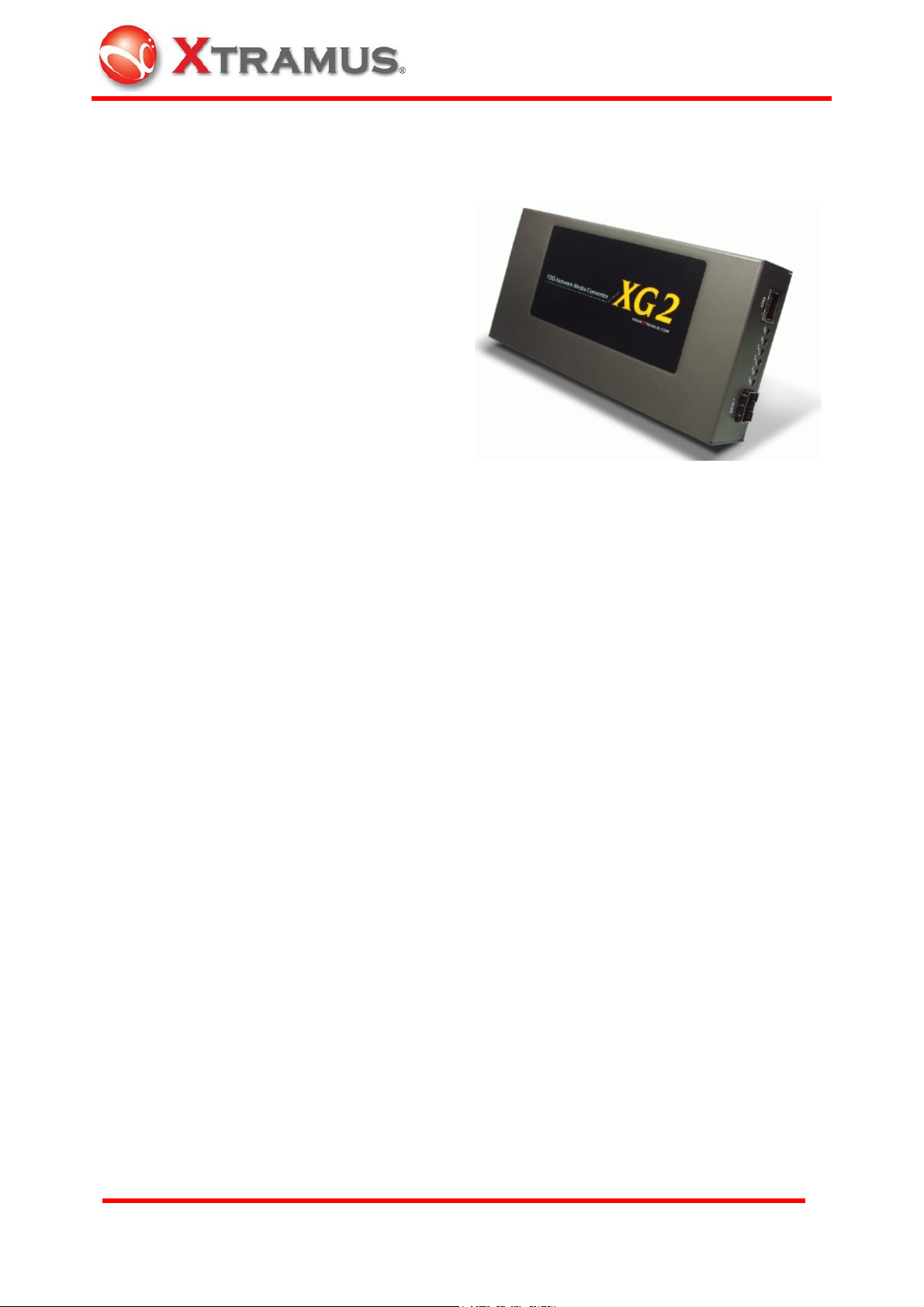
This chapter tells you how to install XG2 in your network environment.
XG2 is an equipment that administrator only has to plug fiber/cable and then it works, as easy as
general Ethernet switch without extra configuration.
Hence, the most important things are not the operation of XG2. The configuration of cabling,
selections of physical media and applications in your environment is more important.
3.1 Choice of UTP Cable and Optical fiber
3.1.1 10GBASE-T (Copper Wire)
10GBASE-T, or IEEE 802.3an-2006, is a standard released in 2006 to provide 10 gigabit/second
connections over unshielded or shielded twisted pair cables, over distances up to 100 meters
(330 ft). 10GBASE-T cable infrastructure can also be used for 1000BASE-T, allowing a gradual
upgrade from 1000BASE-T, and auto-negotiation to select which speed to use.
Connectors
10GBASE-T uses 650 MHz versions of the venerable IEC 60603-7 8P8C (RJ-45) connectors,
that is already widely used in Ethernet.
Cables
10GBASE-T works up to 55 m (180 ft) with existing Category 6 cabling. In order to allow
deployment at the usual 100 m (330 ft), the standard uses a new partitioned Category 6a cable
specification, designed to reduce crosstalk between UTP cables.
Category of UTP network cable for reference
Cat 5
Provides performance of up to 100 MHz, and was frequently used on 100 Mbps Ethernet
networks. May be unsuitable for 1000BASE-T gigabit Ethernet.
Cat 5e
Provides performance of up to 100 MHz, and is frequently used for both 100 Mbit/s and Gigabit
Ethernet networks.
Cat 6
Provides performance of up to 250 MHz, more than double of category 5 and 5e. It works up to
55 m (180 ft) for 10Gbps Ethernet.
Cat 6a
Provides performance of up to 500 MHz, double of category 6. It is suitable for 10GBASE-T. It
works up to 100 m (330 ft) for 10Gbps Ethernet. All the cables above does not have
individually-shielded pairs as the picture below, including Cat 6a.

10
E-mail: [email protected]om
Website: www.Xtramus.com
XTRAMUS TECHNOLOGIES®
Cat 7
This standard specifies four individually-shielded pairs (STP) inside an overall shield. Designed
for transmission at frequencies up to 600 MHz. It has better performance than Cat 6a.
3.1.2 10GBASE-R (Optical Fiber)
10GBASE-R is 10Gbps Ethernet connection that based on IEEE802.3ae. It uses fiber as
transmission media with different specification of fiber, connector and transceiver. XG2 uses two
standards, 10GBASE-LR and 10GBASE-SR.
10GBASE-SR
10GBASE-SR ("short range") uses 64B/66B encoding and 850 nm wavelength lasers. It is
designed to support short distances over deployed multi-mode fiber cabling, it has a range of
between 26 meters (85 ft) and 82 meters (270 ft) depending on cable type. It also supports 300
meters (980 ft) operation over new, 50 µm 2000 MHz•km OM3 multi-mode fiber (MMF).
The transmitter can be implemented with a VCSEL (Vertical Cavity Surface Emitting Laser) which
is low cost and low power. MMF has the advantage of having lower cost connectors than SMF
(single-mode fiber) due to its wider core.
10GBASE-SR delivers the lowest cost, lowest power and smallest form factor optical modules.
10GBASE-LR
10GBASE-LR ("long range") is a Long Range Optical technology delivering serialized 10 gigabit
Ethernet over a laser with 1310 nm wavelength connection on single-mode fiber via IEEE 802.3
Clause 49 64B-66B Physical Coding Sub layer (PCS) using a line rate of 10.3125.

11
E-mail: [email protected]om
Website: www.Xtramus.com
XTRAMUS TECHNOLOGIES®
Single-mode optical cabling is used to interconnect transceivers at a distance spaced at 10
kilometers (6.2 mi), but it can often reach distances of up to 25 kilometers (16 mi) with no data
loss.
Fabry-Perot lasers are commonly used in 10GBASE-LR optical modules. Fabry-Perot lasers are
more expensive than VCSELs (mentioned above) but their high power and focused beam allow
efficient coupling into the small core of single mode fiber.
Fiber Specification
Fibers which support many propagation paths or transverse modes are called multi-mode fibers
(MMF). Fibers which can only support a single mode are called single-mode fibers (SMF).
Multi-mode fibers generally have a larger core diameter, and are used for short-distance
communication links and for applications where high power must be transmitted. Single-mode
fibers are used for most communication links longer than 200 meters.
Fiber Buffer/Jacket
color Meaning
Yellow Single-mode optical fiber, long distance connection
Orange Multi-mode optical fiber, short distance connection
3.2 Connection of UTP Cable and Optical fiber
3.2.1 10GBASE-T (Copper Wire)
10GBASE-T uses the same RJ-45 connector that is the same as original 100M/1000Mbps
Ethernet network. Plug the RJ-45 connector into the port of 10Gbps, then it is ready to work.
Watch the LED status of Link/ACT of port Ato know the connection status.
3.2.2 10GBASE-R (Optical Fiber)
The connection of optical fiber can be departed to 4 sections
Optical Fiber
Fiber Connector
SFP+ Transceiver
Plug into Connect Connect
Cat. 6, Cat. 6a UTP Cable
RJ-45 Connector
Plug into
LR or SR Mode
Transceiver

12
E-mail: [email protected]om
Website: www.Xtramus.com
XTRAMUS TECHNOLOGIES®
Optical Fiber:
As the description above, there are Single-mode and Multi-mode optical fiber. Both of them can
be used for XG2
Fiber Connector:
Unlike RJ-45 connector, the fiber can be removed from SFP+ transceiver easily. At two ends of
fiber, it has connector that can attach to SFP+ transceiver. There are two fibers for one SFP+
transceiver. One fiber is for receiving and one fiber is for transmission. The picture below is
called LC connector that can attach to SFP+ transceiver.
Transceiver (Connector):
SFP+ Transceiver is the hardware that is pluggable into the body of XG2. Unlike RJ-45
connector that there is no component inside at all, SFP+ Transceiver is an active component that
consumes power from XG2 and it has the key function that convert signals between optical data
flow and electronic data flow.
A: Handgrip to remove module from XG2 easily
B: Connection from LC fiber connector that is described above
C: Bottom of the transceiver module
D: Electronic conductor to XG2 body
E: Size of matchstick.
For different transmission purpose, the component inside SFP+ form factor can be 10BASE-LR
or 10BAST-SR mode.
When SFP+ transceiver is plugged into the XG2, the LED of SFP+ isAmber. If the inserted SFP+
transceiver is attached by a fiber with LC connector with going on signaling, the LED becomes
Green. The LED of LR is either Green for 10BASE-LR mode or Amber for 10BASE-SR mode.
Details are shown at the table below
A
B C D
E

13
E-mail: [email protected]om
Website: www.Xtramus.com
XTRAMUS TECHNOLOGIES®
LED Status
Type Label LED Description
Amber Remind user that the SFP+ form
factor transceiver (connector) is
connected.
Green Transceiver (connector) with powered
optical fiber is connected.
Fiber
Connector
(Transceiver)
Status
SFP+
OFF No SFP+ transceiver (connector) is
plugged.
Green Connector of LR Transceiver is
plugged.
10BASE-R
Mode LR
Amber Connector of SR Transceiver is
plugged.
SFP+ LED LR LED Description
No SFP+ form factor transceiver (connector) is plugged.
(Amber)
(Green) LR mode SFP+ form factor transceiver (connector) is plugged.
No powered fiber is connected
(Amber)
(Amber) SR mode SFP+ form factor transceiver (connector) is plugged.
No powered fiber is connected
(Green)
(Green) LR mode SFP+ form factor transceiver (connector) is plugged.
Powerd fiber is connected
(Green)
(Amber) SR mode SFP+ form factor transceiver (connector) is plugged.
Powerd fiber is connected
The size and specification of transceiver are independent from the Ethernet protocol transmitted
and received inside fiber.
Hence, there is no problem for the fiber connection between XG2's SFP+ transceiver (connector)
and XFP transceiver (connector) that is plugged at other device.
Note: SFP+ Transceiver that complies with 10GBASE-LR/SR standard is suitable for XG2. For
recommended SFP+ Transceiver, please contact with distributor.
Fiber
SFP+ Transceiver XFP Transceiver
Other 10Gbps
Device

14
E-mail: [email protected]om
Website: www.Xtramus.com
XTRAMUS TECHNOLOGIES®
3.3 Application for your network
3.3.1 Application for University
10Gbps speed Ethernet connection may not be common seen in the office; however,
administrator may has Gigabit Ethernet in the control room of office already. Get a 10Gbps
Ethernet connection from backbone and distribute it to different Gigabit Ethernet segment for
different building or organization is practical and more cost-effective. Here is an example of
possible plan.
This example is a possible network structure of a university.
A: Internet backbone from ISP.
B: The distance from the central office to the university might be long, so construct the
connection via single-mode optical fiber with 10BASE-LR mode, which can extend the distance
beyond several tenth of kilometer.
C: XG2 is located at the computer center of university.
D: After the conversion of XG2, expensive equipment for transmitting/receiving network data via
optical fiber is not required afterward.
E: Full 10Gbps Ethernet Switch may beyond your budget or it is not available. Some 1Gbps
Switch reserves a swappable slot for the upgrade of future technology. Plug a 10Gbps module
with one 10Gbps port to this kind of Switch is enough for this application.
F: After the distribution of 1Gbps Ethernet Switch with attached 10Gbps module, several 1Gbps
connections can be distributed to different buildings inside the university by Cat. 6a network
cable, which can be extended to 100 meters.
G, H, I: Different buildings or departments in one building. General switch with 1Gbps and
100Mbps ports can be connected here for end-user.
A
B
C D E
F
G H I

15
E-mail: [email protected]om
Website: www.Xtramus.com
XTRAMUS TECHNOLOGIES®
3.3.2 Application for Online Game Company
For ISP or online game company, XG2 may also save lots of money for cabling their control room.
ISP runs lots of customer's service such as e-mail server, web server or any co-located network
services in the control room. These equipments may not have interface for the connection of
optical fiber. For online game company, administrator may have lots of online game servers that
need high-speed connection to Internet backbone in the control room.
A: Client users from Internet
B: For the mass requests from general public. The main requests come from other ISP in
Internet.
C: The distance from the other ISP to the game company might be long, so construct the
connection via single-mode optical fiber with 10BASE-LR mode, which can extend the distance
beyond several tenth of kilometer.
D: XG2 is located at the control room of the game company.
E: After the conversion of XG2, transceiver and equipment of optical fiber is not required in the
control room afterward.
F: Depending on the requirement of loading, Ethernet Switch with full 10Gbps ports or partial
10Gbps/1Gbps ports is configured for the distribution of data flow.
G: Assume that the bandwidth requirement of co-located mail servers for some companies is not
heavy; connect them to 1Gbps port of 10Gbps switch.
H: Assume that the bandwidth requirement of online game servers is heavy; connect them to
10Gbps port of 10Gbps switch.
l: Different kinds of server with different applications are located side by side by connections from
10Gbps Ethernet Switch via inexpensive Cat.6 cable.
A
B
C
D E
F
G
H
I

16
E-mail: [email protected]om
Website: www.Xtramus.com
XTRAMUS TECHNOLOGIES®
3.3.3 Application for Home User
A schematic illustrating how the FTTX architectures vary with regard to the distance between the
optical fiber and the end-user.
Fiber to the x (FTTX) is a generic term for any network architecture that uses optical fiber to
replace all or part of the usual copper local loop used for telecommunications. The four
technologies, in order of an increasingly longer fiber loop are:
¾Fiber to the node / neighborhood (FTTN)
¾Fiber to the curb (FTTC) / Fiber to the kerb (FTTK)
¾Fiber to the building (FTTB)
¾Fiber to the home (FTTH)
The building on the left is the central office; the building on the right is one of the buildings served
by the central office. The white or gray blocks represent separate rooms or office spaces within
the same building.
A: Central Office of ISP
B: Network connection via optical fiber
C: Installation of XG2 for media conversion
D: Network connection via copper wire. It can be Cat. 6a cable (under 300 meters) or telephone
line via xDSL (Technologies such as VDSL provide high speed, short-range link are used often in
FTTx service)
E: Different rooms of home or different compartments in the same building.
F: XG2 can be located at any place that near or away from building, depending on the service to
home users.
E
A B C D
F

17
E-mail: [email protected]om
Website: www.Xtramus.com
XTRAMUS TECHNOLOGIES®
Advantage for ISP
For the time before, if the client has requirement of lots bandwidth, ISP has to cabling several
fibers with gigabit connection to the same location and distributes the connection by Gigabit
switch or media converter to copper wired destination.
Depends on the bandwidth required for client, ISP can configure a XG2 media converter between
the connection of light blue and dark blue line in the graph. With 10G Ethernet conversion
between fiber and copper wire, ISP can provide heavyweight bandwidth service that is closer to
the client without spending too much cost.

18
E-mail: [email protected]om
Website: www.Xtramus.com
XTRAMUS TECHNOLOGIES®
4. Additional Function
4.1 Loopback
XG2 has loopback function for the trouble shooting of network. Loopback test is the method to
send out signal and quickly back to the same source entity to test the transmission and route
problem of infrastructure. Test equipment with this troubleshooting technique sends specific
patterns, and counts any errors that come back (BERT, Bit Error Rate Test).
From the operation of console port, user can active loopback test. When it is enabled, data
stream from test equipment to the XG2 flows returns to their source entity.
Here it illustrates how loopback works.
A: XG2 that loopback function is enable for other test equipment or network infrastructure.
B: Signal with test patterns such as BERT is sent.
D: Signal with test patterns is back to original entity (test equipment).
C: Network equipment or test equipment with 10GBASE-T port that is able to send test patterns
with destination of itself via XG2
E: Network equipment or test equipment with 10GBASE-R port that is able to send test patterns
with destination of itself via XG2
4.1.1 Operation via Console Port
After connecting the COM port of PC to Console port of XG2 via Console cable, power on the PC
and configure the PC parameters as following path of Windows (by using Windows Hyper
Terminal software):
D
C
B
A
D
E
B

19
E-mail: [email protected]om
Website: www.Xtramus.com
XTRAMUS TECHNOLOGIES®
Start ÆAll programs ÆAccessories ÆCommunications ÆHyper Terminal Æ
•Input a name for this connection, such as XG2, and also select an icon for this connection.
•Select the COM port of PC for this connection. Generally, it is COM1.
•Configure the parameter of COM port as below, 38400, 8, None, 1, None
Table of contents
Other Xtramus Media Converter manuals
Popular Media Converter manuals by other brands

Converters.TV
Converters.TV 15107 Operation manual

Mhdt Labs
Mhdt Labs Pagoda Balanced INSTRUCTIONS AND MANUAL

Absolute Process Instruments
Absolute Process Instruments DuoPak APD 2036 D manual

CYP
CYP CPLUS-V11PE8 Operation manual

madVR Labs
madVR Labs Envy Setup guide

TRENDnet
TRENDnet TFC-1000 Quick installation guide