Xtramus MCS-2160 User manual

MCS-2160
Media Converter
User’s Manual
USM Ver 1.9.1

Foreword
Copyright
Copyright © 2012 Xtramus Technologies, all rights reserved. The information contained in this document is the property of Xtramus
Technologies. No part of this publication shall be reproduced, stored in a retrieval system, or transmitted, in any form or by any
means, without the prior written permission of Xtramus Technologies.
Disclaimer
The information contained in this document is subject to change without notice and does not represent a commitment on the part of
Xtramus Technologies. The information in this document is believed to be accurate and reliable. However, Xtramus Technologies
assumes no responsibility or liability for any errors or inaccuracies that may appear in the document.
Trademarks
MCS-2160 is a trademark or registered trademark of Xtramus Technologies. All other trademarks and registered trademarks are
the property of their respective owners.
Warranty
Xtramus Technologies warrants for the hardware provided along with this document under proper usage and conditions in normal
environment; any improper operation or in irregular environment may possibly cause this product NOT function well. For detailed
terms, please contact your local dealer.
Contact Information
Xtramus Technologies
E-mail: [email protected]
Website: www.xtramus.com
Tel: +886-2-8227-6611
Fax: +886-2-8227-6622
2E-mail: sales@xtramus.com
Website: www.Xtramus.com
XTRAMUS TECHNOLOGIES®

Revision History
Date Version History
2011/10/11 1.0 First draft version
2011/11/04 1.1
1. Modifying XC-M667 figure. (Page 12)
2. Added new figure for MCS-FANT-05. (Page 24)
3. Modifying new figure for Management interface. (Page
41-43)
4. Added new subject: “Port A/B SDFR Setting” and “Port
A/B Capture View”. (Page 49 and 50)
2011/12/02 1.2
1. Updating MCS-2160 interface figure. (Page 36)
2. Updating System Information interface’s figure by adding
Syslog Info. (Page 37)
3. Updating System Information interface’s figure by adding
Syslog Info and descriptions. (Page 38)
4. Added Syslog Settings function and 3CDaemon
software’s functions descriptions. (Page 40~42)
5. Updating the Chassis Management interface and
descriptions. (Page 44)
6. Modifying the figure of Chassis Management. (Page 46
and 47)
7. Added Fan Tray interface (M) figure and description.
Added note for auto-refresh of Fan Tray Temperature.
(Page 45)
8. Updating Card Information interface figure, description
and note of auto-refresh for Temperature, Port
Wavelength and Factory. (Page 48)
9. Added Port A/B DDMI figure and descriptions. (Page 49)
10. Added note for auto-refresh of USC counter of the web
interface. (page 53)
2012/01/10 1.3
1. Updating the System information interface by adding the
Fan Tray Information. (Page 39 )
2. Updating the Chassis Management interface. (Page 45-
47)
3. Updating Port A/B DDMI figure and description by
changing the unit mW to dBm. (Page 49)
4. Added Console function. (Page 56-60)
5. Added Telnet access function. (Page 60-62)
6. Page 7, updating Main Applications
2012/03/28 1.4
1. Updating System information interface for License
Information field. (Page 35-37)
2. Adding status capture for 3Cdaemon. (Page 40)
3. Renewing the description of Management functions and
interfaces by adding SNMP v1/2/3, Time, Date, Alarm
mail and cascade display. (Page 39-48, 50)
4. Adding SNMP v1/2/3, Time, Date, Alarm mail command
to Hyper Terminal. (Page 62)
5. Adding cascade screenshot and description on hyper
terminal. (Page 63)
6. Adding SNMP v1/2/3, Time, Date, Alarm mail command
to Hyper Terminal. (Page 67)
7. Adding cascade screenshot and description on telnet.
(Page 68)
2012/04/23 1.5
1. Adding figures and description for FPGA/Firmware
updating progress bar. (Page 56)
3E-mail: sales@xtramus.com
Website: www.Xtramus.com
XTRAMUS TECHNOLOGIES®

Date Version History
2012/04/23 1.5
2. Adding figures and description for MCM-W series
Management’s Counter. (Page 49)
3. Adding description about Mail Content on hyper terminal.
(Page 64)
4. Adding description about Mail Content on Telnet. (Page
69)
2012/05/10 1.6
1. Updating new figure and description for Language option.
(Page 37)
2. Updating new figure and description for License
information. (Page 38)
3. Adding new function (safety and configuration settings)
description for Management. (Page 40)
4. Adding Download MIB File function for SNMP settings.
(Page 45)
5. Adding Safety and Configuration settings description and
figures. (Page 48)
6. Updating Media Converter Management function
description and figures. (Page 49-50)
7. Updating Chassis Management interface figure. (Page
51)
8. Updating Counter’ chassis id and slot id description and
figure. (Page 56)
9. Adding Language option’s figure and description. (Page
61)
10. Updating MCS-2160 system update description for Hyper
Terminal and Telnet. (Page 64 and 69)
11. Updating XC module cards update description for Hyper
Terminal and Telnet. (Page 66 and 71)
2012/05/28 1.7
1. Adding description of Chinese Traditional option on the
Language function. (Page 37)
2. Adding description and figure of Chinese Traditional
option on the Language function. (Page 61)
3. Updating new figure of USC Counter for displaying the
module card model. (Page 56)
4. Updating the description and figure of Mail Configuration
for Switch ON/OFF ÆEnable. (Page 47)
5. Updating the description and figure of Safety
Configuration for Switch ON/OFF ÆEnable. (Page 48)
6. Adding description about Web Management will auto log
out when accessing MCS-2160 via Telnet. (Page 69)
7. Adding description about Web Management or Telnet will
auto log out when accessing MCS-2160 via Hyper
Terminal. (Page 62)
8. Adding description and figure showing the progress bar
during the upgrading of MCS-2160 or XC module via
console and Tftpd32 software. (Page 67)
4E-mail: sales@xtramus.com
Website: www.Xtramus.com
XTRAMUS TECHNOLOGIES®

Date Version History
2012/06/05 1.8
1. Adding Link Loss Forwarding (LLF) function. (Page 9)
2. Adding Japanese and Korean Language description.
(Page 38)
3. Adding note describing XC-8SXX module cards don’t
support Port Configuration function. (Page 54)
4. Adding description and figure about the XC-7S81 module
card supporting Port Configuration function. (Page 61-62)
5. Adding description and figure for Japanese and Korean
language. (Page 64)
2012/07/19 1.9
1. Add information about auto detecting a new user (MCM)
of the same Network Segment. (Page 50)
2. Updating new figure for Chassis Management. (Page 52)
3. Adding description for Chassis Overview. (Page 63)
4. Adding description about Syslog (Logip) and Safety
functions for hyper terminal and telnet. (Page 68 and 74)
2012/09/24 1.9.1
1. Upgrading system firmware MGM_RTC_v1.1b003
description note in Web user interface, Hyper Terminal
and Telnet. (Page 64, 68, 74)
2. Updating Media Converter Management figure and
description.(Page 50-51)
3. Adding description about showing detail information of
MCS-FANT on Hyper Terminal and Telnet. (Page 68, 74)
5E-mail: sales@xtramus.com
Website: www.Xtramus.com
XTRAMUS TECHNOLOGIES®

Table of Contents
Foreword ..........................................................................................................................................2
Revision History ..............................................................................................................................3
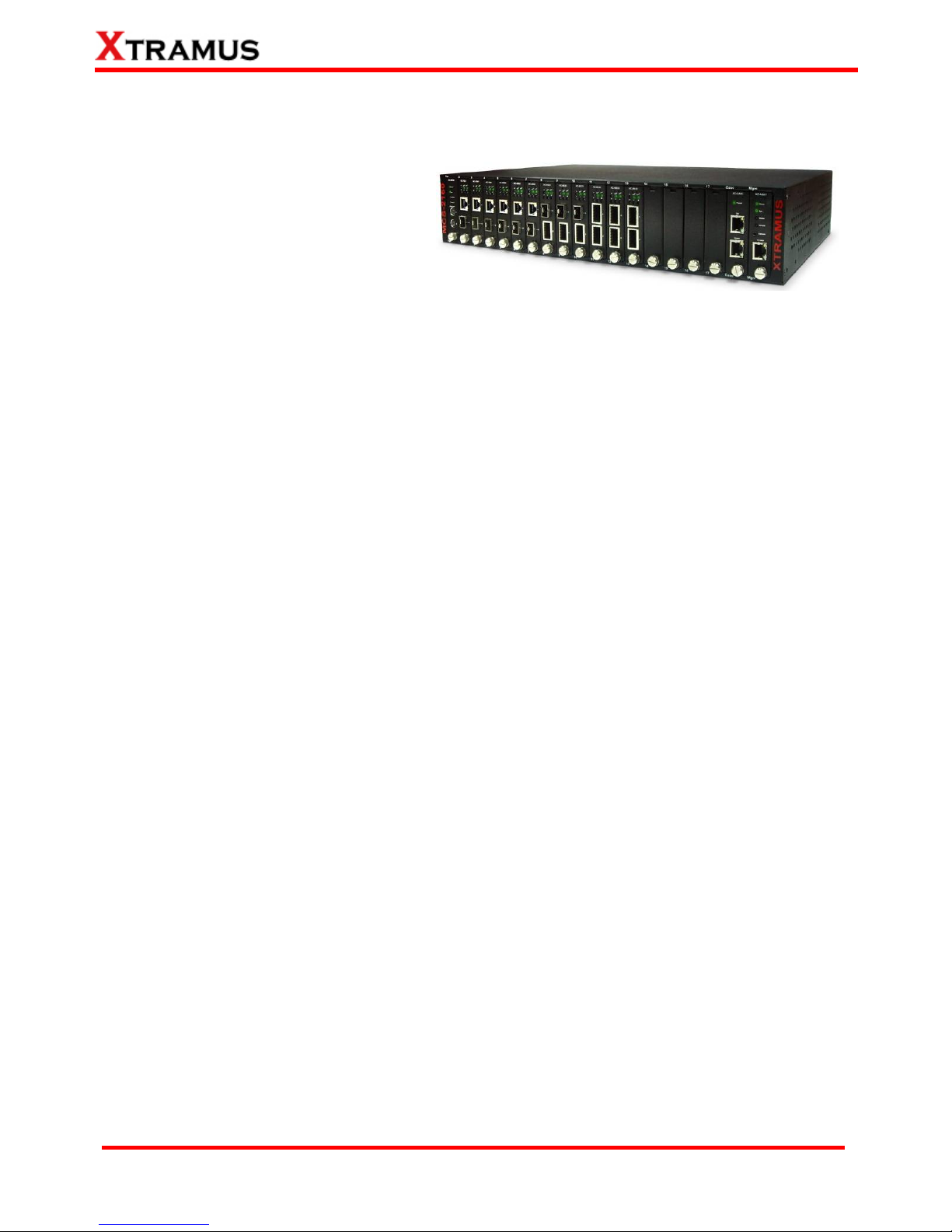
1. MCS-2160 Overview ....................................................................................................................8
1.1. General Descriptions of MCS-2160...................................................................................8
1.2. Features, Key Advantages, and Main Applications of MCS-2160 ..................................9
1.3. MCS-2160 Functions Overview .......................................................................................10
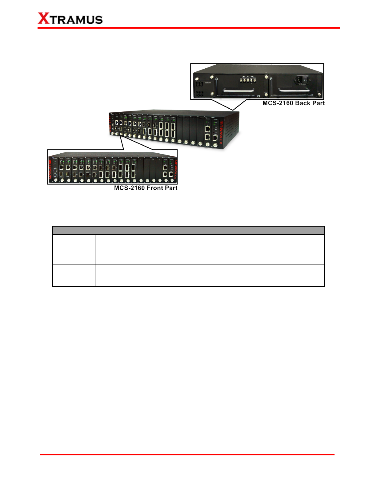
1.3.1. MCS-2160 Outer Case .................................................................................................10
1.3.2. MCS-2160 Front Part ................................................................................................... 11
1.3.3. Module Cards...............................................................................................................12
1.3.3.1. System Module Cards ..........................................................................................13
A. System Module Card – XC-SFAN.................................................................................13
B. System Module Card – XM-M667 .................................................................................14
C. System Module Card – XC-CASC ................................................................................15
1.3.3.2. Media Converter Module Cards...........................................................................16
A. Media Converter Module Card – XC-7S81...................................................................16
B. Media Converter Module Card – XC-8S22...................................................................17
C. Media Converter Module Card – XC-8S23...................................................................18
D. Media Converter Module Card – XC-8S33...................................................................19
E. Media Converter Module Card – XC-8S82...................................................................20
F. Media Converter Module Card – XC-8S83 ...................................................................21
1.3.4. MCS-2160 Rear End.....................................................................................................22
A. XC-RFAN Fan Module ...................................................................................................23
B. XCP-DC-300 & XCP-DC-100..........................................................................................23
C. XCP-AC-300 & XCP-AC-100..........................................................................................24
1.3.5. Optional Fan Tray – MCS-FANT-05.............................................................................25
2. MCS-2160 Installation ...............................................................................................................27
2.1. Choices of UTP Cable and Optical fiber.........................................................................27
2.1.1. 10GBASE-T (Copper Wire)..........................................................................................27
2.1.2. 10GBASE-R (Optical Fiber).........................................................................................28
2.2. Hardware Installation .......................................................................................................30
2.2.1. Bracket installation......................................................................................................30
2.2.2. Module Cards Installation ........................................................................................... 32
2.2.3. Power Module ..............................................................................................................33
2.2.3.1. XCP-DC-300 & XCP-DC-100 .................................................................................33
2.2.3.2. XCP-AC-300 & XCP-AC-100 .................................................................................34
2.2.4. Fan Module...................................................................................................................34
2.2.4.1. XC-SFAN ................................................................................................................34
2.2.4.2. XC-RFAN................................................................................................................35
2.2.4.3. MCS-FANT-05 ........................................................................................................35
3. MCS-2160 Management ............................................................................................................36
3.1. Managing MCS-2160 with Management Webpage.........................................................36
3.1.1. Accessing MCS-2160 Management Webpage........................................................... 37
3.1.2. MCS-2160 Management Webpage – Overview..........................................................38
3.1.3. MCS-2160 Management Webpage – System............................................................. 39
3.1.3.1. System Information ..............................................................................................39
3.1.3.2. Fan Tray Information ............................................................................................40
3.1.4. MCS-2160 Management Webpage – Management....................................................41
A. IP Configuration ............................................................................................................41
B. Syslog Settings .............................................................................................................42
C. User Settings .................................................................................................................45
D. SNMP Settings...............................................................................................................46
E. Time Settings.................................................................................................................47
F. Mail Settings...................................................................................................................48
G. Safety Settings ..............................................................................................................49
6E-mail: sales@xtramus.com
Website: www.Xtramus.com
XTRAMUS TECHNOLOGIES®

H. Configuration Settings .................................................................................................49
I. Media Converter Management.......................................................................................50
J. Chassis Management ....................................................................................................52
a. Information ................................................................................................................ 55
b. Port A/B DDMI ........................................................................................................... 56
c. Counter ...................................................................................................................... 57
d. Upgrade ..................................................................................................................... 58
e. Power Control ........................................................................................................... 59
f. Port A/B USC Setting................................................................................................. 59
g. Port A/B Universal Stream Counter ........................................................................ 60
h. Link Loss Forwarding (LLF) .................................................................................... 60
i. Module Card Options_XC-7S81................................................................................ 61
K. Chassis Overview .........................................................................................................63
3.1.5. MCS-2160 Management Webpage – Maintenance ....................................................64
A. Save Changes................................................................................................................64
B. Update F/W (Firmware) .................................................................................................64
C. System Reboot..............................................................................................................65
D. Factory Defaults ............................................................................................................65
3.1.6. MCS-2160 Management Webpage – Language...........................................................65
3.2.1. HyperTerminal Settings for MCS-2160.......................................................................67
3.2.2. MCS-2160 HyperTerminal Commands ....................................................................... 67
A. MCS-2160 HyperTerminal Command – system ..........................................................68
B. MCS-2160 HyperTerminal Command – ip ...................................................................72
C. MCS-2160 HyperTerminal Command – cls .................................................................72
D. MCS-2160 HyperTerminal Command – logout ...........................................................72
3.3 Managing MCS-2160 with Telnet ......................................................................................73
3.3.1. Telnet Settings for MCS-2160 .....................................................................................73
3.2.2. MCS-2160 Telnet Commands...................................................................................... 73
A. MCS-2160 Telnet Command – system.........................................................................74
B. MCS-2160 Telnet Command – ip..................................................................................77
C. MCS-2160 Telnet Command – cls ................................................................................77
D. MCS-2160 Telnet Command – logout ..........................................................................77
4. MCS-2160 General Specifications............................................................................................78
7E-mail: sales@xtramus.com
Website: www.Xtramus.com
XTRAMUS TECHNOLOGIES®

1. MCS-2160 Overview
1.1. General Descriptions of MCS-2160
MCS-2160 media converter chassis is a
complete and versatile solution for the
applications such as FTTx, CWDM, and
carrier Ethernet. By the diversified speeds
of 1,000Mbps and 10G, Xtramus provides
different XC series module cards for
different applications and can be applied according to your ideal network topology.
Combined with XC series module cards, MCS-2160 media converter chassis provide various interfaces
such as UTP, SFP, SFP+ and XFP. All these interfaces are developed to support the protocols such as
100Base-Tx, 100Base-Fx, 1000Base-T, 1000Base-X, 10GBase-T, 10GBase-LR and 10GBase-SR, thus
making your network more complete and solid.
Also, XC series module cards support MIB Counter Report including counters such as Packet, Byte,
Broadcast packet, Pause Frame, Length: 64 Bytes, Length: 65~127 Bytes, Length: 128~255 Bytes,
Length: 256~511 Bytes, Length: 512~1023 Bytes, Length: 1024~1518 Bytes, Unicast packet, Multicast
packet, CRC Error, IP Checksum Error, Under size packet, and Over size packet.
All XC series module cards are equipped with real-time LEDs which display the status of each port, thus
allowing users to view network status easily.
MCS-2160 media converter chassis provides an easy-to-access Management Webpage, allowing users
to view system status, counters, upgrading firmware/FPGA and network statistics. Moreover, XC-CASC
module card allows you to cascade multiple MCS-2160 chassis for managing these chassis at the same
time.
With various interfaces, MCS-2160 provides different conversions between fibers and copper wires in
10G Ethernet.
8E-mail: sales@xtramus.com
Website: www.Xtramus.com
XTRAMUS TECHNOLOGIES®

1.2. Features, Key Advantages, and Main Applications of MCS-2160
Features
¾Diversified interfaces including SFP, SFP+, UTP and XFP
¾Supports 3R (Re-generation, Re-timing, Re-shaping) Performance
¾Supports Jumbo Frame
¾Supports D/D (Digital Detection) functioned optical transceivers and overload protection
¾Supports easy-to-use Management Webpage that allows users to view system status, counters,
upgrading firmware/FPGA and network statistics
¾Multiple MCS-2160 chassis can be cascaded for system management
¾Replaceable power modules for AC & DC power
¾Supports Link Loss Forwarding
¾Optional Fan Tray (MCS-FANT-05) which can be placed under MCS-2160 chassis for ventilation
Key Advantages
¾Fast connection with multi-function
¾Provide reliable long-distance connection
¾Port supported: SFP, SFP+, UTP and XFP
Main Applications
¾Media converter for network backbone
¾Connection between fiber to copper or fiber to fiber 10G Ethernet equipment
¾Can be applied in Telecommunication room, R&D laboratory, Data center, and etc
¾Providing additional network management options
¾Can be applied in Telecommunication room, R&D laboratory, Data center, etc
9E-mail: sales@xtramus.com
Website: www.Xtramus.com
XTRAMUS TECHNOLOGIES®

1.3. MCS-2160 Functions Overview
1.3.1. MCS-2160 Outer Case
MCS-2160’s outer case consists two parts: Front Part and Back Part. The figure above shows the outer
case of MCS-2160. Outer cases of other MCS-2160 are quite the same and can be related.
MCS-2160 Outer Case Overview
Front Part
MCS-2160 has 16 slots for installation of module cards, where each module card
provides media converting platforms for different types of media. Besides, the
Front Part includes 3 slots with Fan, CASC and Management module card
installed. Please see “1.3.2. MCS-2160 Front Part” for more detailed information.
Back Part
MCS-2160’s back part includes 3 different slots for installation of a DC module,
AC module and a Fan module. Please see “1.3.3. MCS-2160 Back Part” for
more detailed information.
.
10 E-mail: sales@xtramus.com
Website: www.Xtramus.com
XTRAMUS TECHNOLOGIES®

1.3.2. MCS-2160 Front Part
As mentioned in “1.3.1. MCS-2160 Outer Case”, MCS-2160 has 16 slots for installation of media
converter module cards and 3 slots comprising a Fan, CASC and Management module card installed.
Please see the sections down below for more detailed information/specification for MCS-2160 and the
module cards.
MCS-2160 Front Part
XC-SFAN It is a fan module card pre-installed in front part of MCS-2160 chassis.
XC-M667
It is a module card pre-installed in MCS-2160 chassis with 1
Management port for accessing the Management Webpage and 1
Console port for accessing the HyperTerminal settings.
XC-CASC
It is a module card pre-installed in MCS-2160 with 2 ports where each
port can connect another MCS-2160 providing simultaneous access to
the Management Webpage.
Media Converter Module
Card Slots 2-17 Media converter module cards can be inserted in each of slot 2-17.
*Note: XC-SFAN, XC-M667 and XC-CASC do not support hot swap, please, do not withdraw the XC-SFAN, XC-M667
and XC-CASC module card when the system is power on.
*Note2: Do not change XC-M667, XC-CASC and XC-SFAN inserting slot.
11 E-mail: sales@xtramus.com
Website: www.Xtramus.com
XTRAMUS TECHNOLOGIES®

1.3.3. Module Cards
MCS-2160’s module cards can be divided into two categories: System Module Cards and Media
Converter Module Cards.
Module Card Type Module Card Description
System Module Cards
yXC-SFAN
yXC-M667
yXC-CASC
These module cards can provide ventilation for
the MCS-2160 chassis, allowing users to view
counters/perform system maintenance, or
cascade multiple MCS-2160 chassis.
Please note that System Module Cards do not
support hot-swap, and must be installed to their
designated slots on MCS-2160 chassis.
Media Converter
Module Cards
yXC-7S81
yXC-8S22
yXC-8S23
yXC-8S82
yXC-8S33
yXC-8S83
Module cards for media converting. These Media
Converter Cards can be installed in MCS-2160
Slot 2~17 and support hot-swap.
Please see the sections down below for more detail information regarding to MCS-2160 Module Cards.
12 E-mail: sales@xtramus.com
Website: www.Xtramus.com
XTRAMUS TECHNOLOGIES®

1.3.3.1. System Module Cards
A. System Module Card – XC-SFAN
The XC-SFAN comes with your MCS-2160 chassis, and shall be installed on the Fan slot located on the
far left side of MCS-2160 chassis. This module card provides ventilation for the MCS-2160 chassis.
Also, XC-SFAN’s CTRL + PWR and PWR ports are designed to provide power source and gather
information for MCS-FANT fan tray. When connecting XC-SFAN to MCS-FANT fan tray, please do so by
connect to MCS-SFAN’s CTRL + PWR port to MCS-FANT’s CTRL + PWR port, and XC-SFAN’s PWR
port to MCS-FANT’s PWR port.
If you cross connect between CTRL + PWR port and PWR port of XC-SFAN and MCS-FANT, MCS-2160
will be seriously damaged.
Interface Ports
CTRL + PWR 8-Pin Mini-Din Port which can provide power for MCS-FANT and
system information regarding to MCS-FANT
PWR 8-Pin Mini-Din Port which can provide power for MCS-FANT
LED
Green ON XC-SFAN is power on
Power Green OFF XC-SFAN is power off
Green ON XC-SFAN is powering up properly
Sys Green OFF XC-SFAN is power off
Status 0 User-defined LED
Status 1 User-defined LED
*Note: XC-SFAN does not support hot-swap. Please do not draw the XC-SFAN module card from
MCS-2160 chassis when the system is power on.
13 E-mail: sales@xtramus.com
Website: www.Xtramus.com
XTRAMUS TECHNOLOGIES®

B. System Module Card – XM-M667
The XC-M667 comes with your MCS-2160 chassis, and shall be installed on the Mgm slot located on
the far right side of MCS-2160 chassis. This module card allows you to manage MCS-2160 chassis
via management webpage.
To access the Management Web Page of MCS-2160 for configuration on your browser, please
connect a RJ45 cable between the Management port of MCS-2160 and your PC.
To configure MCS-2160 on your PC (Telnet or Hyper Terminal), please connect a 2.5mm Phone Jack
to RS232 between your PC and Console Port of MCS-2160, where the 2.5mm Phone Jack end must
be plug in the Console Port of MCS-2160 and the RS232 end must be connect to your PC.
Interface Ports
Console Port One 2.5mm Phone Jack Port for managing MCS-2160 via HyperTerminal
Management Port One 10/100M RJ45 Port for managing MCS-2160 via management webpage
LED
Green ON XC-M667 is power on
Power Green OFF XC-M667is power off
Yellow ON XC-M667 is booting and preparing for test
Green ON
(Blinking) XC-M667 is booting properly and is ready for test
Sys
Green OFF XC-M667 is power off
Master User defined LED
Remote User defined LED
*Note: XC-M667 does not support hot-swap. Please do not draw the XC-M667 module card from MCS-2160
chassis when the system is power on.
14 E-mail: sales@xtramus.com
Website: www.Xtramus.com
XTRAMUS TECHNOLOGIES®

C. System Module Card – XC-CASC
The XC-CASC comes with your MCS-2160 chassis, and shall be installed on the Casc slot located on
the right side of MCS-2160 chassis (next to XC-M667 module card). This module card allows you to
cascade multiple MCS-2160 chassis.
On a rack mount structure with numerous MCS-2160 installed, you can inter-connect a MCS-2160
with another MCS-2160 situated above or below by using a RJ45 cable connecting theirs Port (Up) or
Port (Down). By doing the inter-connection, you can access the Management Web Page for all the
inter-connected MCS-2160 by only linking one of theirs XC-M667 Management Port on your PC.
Interface Ports
Port (Up) One 10/100M RJ45 Port for cascading another MCS-2160 chassis
Port (Down) One 10/100M RJ45 Port for cascading another MCS-2160 chassis
LED
Green ON MCS-2160 is power on
Power Green OFF MCS-2160 is power off
*Note: XC-CASC does not support hot-swap. Please do not draw the XC-CASC module card from MCS-2160
chassis when the system is power on.
15 E-mail: sales@xtramus.com
Website: www.Xtramus.com
XTRAMUS TECHNOLOGIES®

1.3.3.2. Media Converter Module Cards
A. Media Converter Module Card – XC-7S81
XC-7S81 Front Panel Specification
Port A RJ45
Interface Port B SFP
Data Transfer Rate 1000 Mbps
Ethernet Mode 1000Base-T
1000Base-X
LED Status
Green ON XC-7S81 is power on.
Power Green OFF XC-7S81 is power off.
Green ON XC-7S81 is booting properly and is ready for
tests.
SYS
Yellow ON Error occurred when booting XC-7S81.
Green ON Port A/B is connected.
A/B Green Blinking Port A/B is transmitting/receiving data.
▇User-defined LED
▲User-defined LED
Note: All LEDS will be off when upgrading FPGA/Firmware
16 E-mail: sales@xtramus.com
Website: www.Xtramus.com
XTRAMUS TECHNOLOGIES®

B. Media Converter Module Card – XC-8S22
XC-8S22 Front Panel Specification
Port A SFP+
Interface Port B SFP+
Data Transfer Rate 10Gbps
Ethernet Mode 10GBase-LR
10GBase-SR
LED Status
Green ON XC-8S22 is power on.
Power Green OFF XC-8S22 is power off.
Green ON XC-8S22 is booting properly and is ready for
tests.
SYS
Yellow ON Error occurred when booting XC-8S22.
Green ON Port A/B is connected.
A/B Green Blinking Port A/B is transmitting/receiving data.
▇User-defined LED
▲User-defined LED
Note: All LEDS will be off when upgrading FPGA/Firmware
17 E-mail: sales@xtramus.com
Website: www.Xtramus.com
XTRAMUS TECHNOLOGIES®

C. Media Converter Module Card – XC-8S23
XC-8S23 Front Panel Specification
Port A SFP+
Interface Port B XFP
Data Transfer Rate 10Gbps
Ethernet Mode 10GBase-LR
10GBase-SR
LED Status
Green ON XC-8S23 is power on.
Power Green OFF XC-8S23 is power off.
Green ON XC-8S23 is booting properly and is ready for
tests.
SYS
Yellow ON Error occurred when booting XC-8S23.
Green ON Port A/B is connected.
A/B Green Blinking Port A/B is transmitting/receiving data.
▇User-defined LED
▲User-defined LED
Note: All LEDS will be off when upgrading FPGA/Firmware
18 E-mail: sales@xtramus.com
Website: www.Xtramus.com
XTRAMUS TECHNOLOGIES®

D. Media Converter Module Card – XC-8S33
XC-8S33 Front Panel Specification
Port A XFP
Interface Port B XFP
Data Transfer Rate 10Gbps
Ethernet Mode 10GBase-LR
10GBase-SR
LED Status
Green ON XC-8S33 is power on.
Power Green OFF XC-8S33 is power off.
Green ON XC-8S33 is booting properly and is ready for
tests.
SYS
Yellow ON Error occurred when booting XC-8S33.
Green ON Port A/B is connected.
A/B Green Blinking Port A/B is transmitting/receiving data.
▇User-defined LED
▲User-defined LED
Note: All LEDS will be off when upgrading FPGA/Firmware
19 E-mail: sales@xtramus.com
Website: www.Xtramus.com
XTRAMUS TECHNOLOGIES®

E. Media Converter Module Card – XC-8S82
XC-8S82 Front Panel Specification
Port A RJ45
Interface Port B SFP+
Data Transfer Rate 10Gbps
Ethernet Mode
10GBase-LR
10GBase-SR
10GBase-T
LED Status
Green ON XC-8S82 is power on.
Power Green OFF XC-8S82 is power off.
Green ON XC-8S82 is booting properly and is ready for
tests.
SYS
Yellow ON Error occurred when booting XC-8S82.
Green ON Port A/B is connected.
A/B Green Blinking Port A/B is transmitting/receiving data.
▇User-defined LED
▲User-defined LED
Note: All LEDS will be off when upgrading FPGA/Firmware
20 E-mail: sales@xtramus.com
Website: www.Xtramus.com
XTRAMUS TECHNOLOGIES®
Table of contents
Other Xtramus Media Converter manuals