Xtreme XB-300SLA User manual

0
XB-300SLA & XB-305SLA
Electric Mountain bike
Owner’s Manual

1
IMPORTANT INFORMATION
FULLY CHARGE BATTERIES BEFORE FIRST USE - Batteries should be fully charged immediately when they are received and immediately after
each use for the recommended charge times (see below)
• 12V12Ah Sealed Lead Acid Batteries: 6-8 hours
FACTORSTOMAXIMIZETHERANGEOFYOURELECTRICBICYCLE
RIDER INPUT - the more the rider pedals the further the distance traveled. Continuous riding, as opposed to frequent stopping and starting, will yield the g
greatest range possible
ELEVATION GAIN - the flatter the road the further the distance traveled
WEATHER
- cold weather can adversely affect the battery capacity
TERRAIN - the smoother the terrain (roadways vs. fireroads, etc.) the further the distance traveled
RIDER WEIGHT
- the lighter the rider, resulting in less drain on the batteries, the further distance traveled
RIDER BICYCLE MAINTENANCE
- a properly maintained bicycle will yield the greatest range possible
RIDER TIRE PRESSURE
- properly inflated tires have less rolling resistance and will be easier to pedal
BATTERIES - properly charged and maintained batteries will yield the greatest range possible. Batteries stored in cold areas (below 50 degrees Fahrenheit / 10
degrees Celsius) will show reduced range. Batteries that have not been kept in optimum condition will show reduced range and run time.

2
TABLEOFCONTENTS
ImportantInformation………………………………………………………………………………………….. 1
Table Of Contents………………………………………………………………………………………………2
Terminology & Battery Systems…………………………………………………………………………………3
XB-300SLA&XB-305SLAElectricBicycle…………………………………………………………………..... 4
RequiredTools…………………………………………………………………………………………………5
Before You Ride……………………………………………………………………………………………….. 6-8
Safety Checklist………………………………………………………………………………………………....9-10
Bicycle Care……………………………………………………………………………………………………10-13
BasicMaintenance…………………………………………………………………………………………10
Throttle……………………………………………………………………………………………………11
Battery Care and Information………………………………………………………………………………..11-12
Charger……………………………………………………………………………………………………12-13
Bicycle Assembly………………………………………………………………………………………………13-20
Getting Started…………………………………………………………………………………………….. 13
Stem and Handlebars……………………………………………………………………………………….14-16
Forks……………………………………………………………………………………………………....17
Seat and Seat Post…………………………………………………………………………………………..18
Front Wheel………………………………………………………………………………………………..19
Disc Brakes………………………………………………………………………………………………...20
Derailleur Systems…………………………………………………………………………………………….....21
Drive Train……………………………………………………………………………………………………..22
Troubleshooting………………………………………………………………………………………………....23-24
Specifications…………………………………………………………………………………………………...25
How To Guide………………………………………………………………………………………………….26-28
How To Check Wire Terminals If Battery Not Charging Properly……………………………………………...26
HowToAdjustWinzipBrake………………………………………………………………………………26-27
How To Replace Brake Lever………………………………………………………………………………27
How To Adjust Derailleur………………………………………………………………………………….. 27
How To Remove Rear Wheel………………………………………………………………………………27-28
HowToReplacePedalShaft……………………………………………………………………………….. 28
Wiring Diagram……………………………………………………………………………………………….. 29-30
General Information/Tech Support………………………………………………………………………………..31
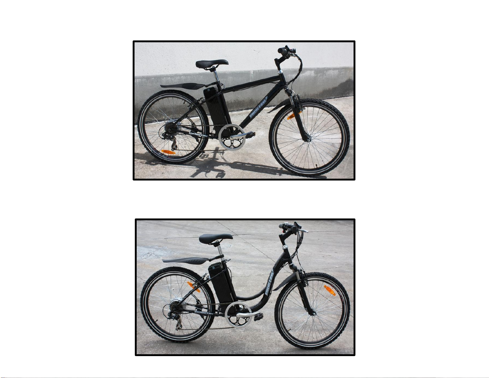
3
XB-305SLA
XB-300SLA

4
!
paRt
1 -
paRts
identi
F
ica
tion
Warning / important -
t
ake notice of this symbol throughout this manual and pay
particular attention to the instructions blocked off and preceded by this symbol.
TERMINOLOGY
POWER Systems
P
AS
–Pedal Assist - Asensor ring and pickup mounted near the bottom bracket allow the bicycle to sense forward pedaling and
apply power.
T
AG
–Twist and Go - A rider-controlled system, the motor activates only when the handlebar throttle is turned.
P
AS
/
T
A
G –Pedal Assist or Twist and Go - Ahandlebar-mounted button allows selection of PAS or TAG modes.

5
!
Your new bicycle was partially assembled in the factory and then partially disassembled for shipping. You may have purchased the bicycle already
fully assembled and ready to ride OR in the shipping carton in the partially disassembled form. The following instructions will enable you to prepare
your bicycle for years of enjoyable cycling. For more details on inspection, lubrication, maintenance and adjustment of any area please refer to the
relevant sections in this manual. If you have questions about your ability to properly assemble this unit, please consult a qualified bicycle service
specialist before riding.
T
YPICAL
T
OOLS REQUIRED:
•Phillips head screw driver
•2.5mm, 3mm, 4mm, 5mm 6mm & 8mm Allen keys
•Adjustable wrench or a 8mm, 9mm, 10mm, 13mm, 14mm,
15mm & 17mm open/box end wrenches
•A pair of pliers with cable cutting ability
T
o avoid injury, this product must be properly assembled before use. if your bicycle was obtained assembled, we strongly recommend
that you review the complete assembly instruction.

6
PART
2 -
Beforeyou ride
R
ide
!
BEFORE YOU RIDE
ABOUT THIS MANUAL
It is important for you to understand your new bicycle. By reading this manual before you go out on your first ride, you’ll know how to get better performance, comfort,
and enjoyment from your new bicycle.
It is also important that your first ride on your new bicycle is taken in a controlled environment, away from cars, obstacles, and other distractions.
G
ENER
AL
W
AR
NING
Bicycling can be a hazardous activity even under the best of circumstances. Proper maintenance of your bicycle is your responsibility as it helps reduce the risk of injury.
This manual contains many “Warnings” and “Cautions” concerning the consequences of failure to maintain or inspect your bicycle. Many of the warnings and cautions say
“you may lose control and fall.” Because any fall can result in serious injury or even death, we do not repeat the warning of possible injury or death where ever the risk of
falling is mentioned.
ASPECIALNOTE
FOR P
ARENTS
It is a tragic fact that most bicycle accidents involve children. As a parent or guardian, you bear the responsibility for the activities and safety of your minor child. Among
these responsibilities are to make sure that the bicycle which your child is riding is properly fitted to the child; that it is in good repair and safe operating condition; that you
and your child have learned, understand and obey not only the applicable local motor vehicle, bicycle, and traffic laws, but also the common sense rules of safe and responsible
bicycling. As a parent, you should read this manual before letting your child ride the bicycle. Please make sure that your child always wears an ANSI, ASTM, SNELL
approved bicycle helmet when riding
CORRECT
FRAME SIZE
When selecting a new bicycle, the correct choice of frame size is a very important safety consideration. Most full sized bicycles come in a range of frame sizes.
These sizes usually refer to the distance between the center of the bottom bracket and the top of the frame seat tube.
For safe and comfortable riding there should be clearance of no less than 1 - 2 inches between
the rider and the top tube of the bicycle frame, while the rider straddles the bicycle with both feet flat on the ground.
The ideal clearance will vary between types of bicycles and rider preference. This makes straddling the frame when
off the seat easier and safer in situations such as sudden traffic stops. Women can use a men’s style bicycle to determine the correct size women’s model.
The following chart and diagram will help you make the correct choice. Rider leg length refers to approximate pant inseam.

7
!
RIDING
POSITION
Seat
H
eight
In order to obtain the most comfortable riding position and offer the
best possible pedaling efficiency, the seat height should be set correctly in relation to
the rider’s leg length. The correct seat height should not allow leg strain from
over-extension, and the hips should not rock from side to side when pedaling. While
sitting on the bicycle with one pedal at its lowest point, place the ball of your foot on
that pedal. The correct seat height will allow the knee to be slightly bent in this
position. If the rider then places the heel of that foot on the pedal, the leg should be
almost straight.
Under no circumstances should the seat post project from the frame beyond its
“Minimum insertion” or “Maximum extension” mark. if your seat post
projects from the frame beyond these markings, the seat post or frame may
break. Prior to your first ride, be sure to tighten the seat clamp properly.
a
loose seat clamp or seat post binder can cause damage to the bicycle or can
cause you to lose control and become injured.
Periodically
check to make
sure that the seat clamp is properly tightened
Reach
To obtain maximum comfort, the rider should not overextend his or her
reach when riding.
To adjust this distance, the position of the seat can be altered in relation to the seat
post. (Refer to page 24)
Maximum Height / Minimum
Insertion Mark (Should not be
visible)
Arms not over Extended
Handlebar
stem height
about the
same as seat
height
Pedal at
Bottom Position

8
Handlebar
h
eight
Maximum comfort is usually obtained when the handlebar height is
equal to or slightly higher than the height of the seat. You may wish to
try different heights to find the most comfortable position.
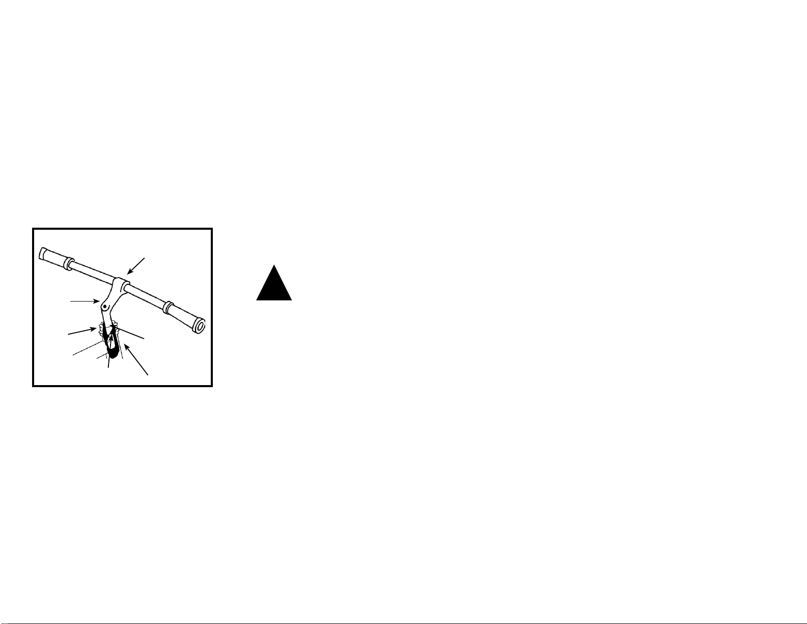
Handlebar Adjustment & Height
The stem’s “Minimum insertion” mark must not be visible above
the top of the headset. If the stem is extended beyond this mark,
the stem may break or damage the fork’s steering tube, which
could cause you to lose control and become injured.
Failure to properly tighten the stem binder bolt, the handlebar
binder bolt, or the bar end extension clamping bolts may
compromise steering action, which could cause you to lose control
and become injured. Place the front wheel of the bicycle between
your legs and attempt to twist the handlebar/stem assembly using
a reasonable amount of force. There should be no play or ability
to move the handlebars in relation to the wheel. If you can twist
the handlebars while the wheel remains in place, do not ride
until proper alignment and is obtained, then tighten all bolts
accordinglybeforeuse.
Handlebar
Binder Bolt
Exceeds 2 1/2”
(64mm)
Stem Wedge Bolt
Maximum Height/
Minimum
Insertion Mark

9
SA
F
ETY
CHEC
K
LIST
Before every ride, it is important to carry out the following safety checks:
1. Brakes
• Ensure front and rear brakes work properly.
• Ensure brake calipers are not over worn and are correctly adjusted.
• Ensure brake control cables are lubricated, correctly adjusted and display no obvious wear.
• Ensure brake control levers are lubricated and tightly secured to the handlebar.
2. Wheels and
t
ires
• Ensure tires are inflated to within the recommended limit as displayed on the tire sidewall.
• Ensure tires have tread and have no bulges or excessive wear.
• Ensure rims run true and have no obvious wobbles or kinks.
• Ensure all wheel spokes are tight and not broken.
• Check that axle nuts are tight. If your bicycle is fitted with quick release axles, make sure locking levers are
correctly tensioned and in the closed position.
3.
S
teering
• Ensure handlebar and stem are correctly adjusted and tightened, and allow proper steering.
• Ensure that the handlebars are set correctly in relation to the forks and the direction of travel.
• Check that the headset locking mechanism is properly adjusted and tightened.
• If the bicycle is fitted with handlebar end extensions, ensure they are properly positioned and tightened.
4. Chain
• Ensure chain is oiled, clean and runs smoothly.
• Extra care is required in wet or dusty conditions
5. Bearings
• Ensure all non-sealed bearings are lubricated, run freely and display no excess movement, grinding or rattling.
• Check headset, wheel bearings, pedal bearings and bottom bracket bearings.
6.
Cranks
and
P
edals
• Ensure pedals are securely tightened to the cranks.
• Ensure cranks are securely tightened to the axle and are not bent.
7.
D
erailleurs
• Check that front and rear mechanisms are adjusted and function properly.
• Ensure shift and brake levers are attached to the handlebar, shift and brake.
• Ensure derailleurs, shift levers and shift and brake cables are properly lubricated.
8. Frame and Fork

10
• Check that the frame and fork are not bent or broken.
• If either is bent or broken, they should be replaced.
9. Accessories
• Ensure that all reflectors are properly fitted and not obscured.
• Ensure all other fittings on the bike are properly and securely fastened, and functioning.
• Ensure the rider is wearing a helmet.
10. Motor and Throttle
• Ensure motor is functioning properly.
• Ensure throttle is functioning properly.
11. Battery
p
ack
• Ensure the batteries are in good operation condition and kept fully charged.
BICYCLE
CARE
BASIC MAINTENANCE
The following procedures will help you maintain your hybrid electric bicycle for years of enjoyable riding.
1. After initial set up be sure to check wheel spokes to make sure they are properly fitted. Be sure to check again after a few rides to ensure proper break in.
Follow up with monthly checks.
2. Properly maintain the batteries by keeping them fully charged when not in use.
3. Do not ride your hybrid electrical bicycle in the water (damp roads, puddles, rain, streams, etc.) and never immerse it in water as the electrical system may be
damaged.
4. Periodically check the wiring and connectors to ensure there is no damage and the connectors have good continuity.
5. For painted frames, dust the surface and remove any loose dirt with a dry cloth. To clean, wipe with a damp cloth soaked in a mild detergent mixture. Dry with a cloth
and polish with car or furniture wax. Use soap and water to clean plastic parts and rubber tires. Chrome plated bikes should be wiped over with a rust preventative
fluid.
6. Store your bicycle under shelter. Avoid leaving it in the rain or exposed to corrosive materials.
7. Riding on the beach or in coastal areas exposes your bicycle to salt which is very corrosive. Wash your bicycle frequently and wipe or spray all unpainted parts with
an anti-rust treatment. Make sure wheel rims are dry so braking performance is not affected. After rain, dry your bicycle and apply anti-rust treatment.
8. If paint has become scratched or chipped to the metal, use touch up paint to prevent rust. Clear nail polish can also be used as a preventative measure.
9. Regularly clean and lubricate all moving parts, tighten components and make adjustments as required.

11
T
HROTTLE
TAG (
T
WIST AND GO)
Before you begin riding, turn the main power switch on, then start riding as you would ride any regular, non motor
assisted bicycle. After you have begun to ride, slowly twist the throttle (on equipped models) towards you. The more you
twist the throttle, the more motor power will be applied to the wheels. You may feel the pedals get a “lighter” feel than
riding without the motor assisting you. Once you have twisted the throttle all the way, the motor will accelerate you to its
full speed of about 18-20mph (28-32 km/h).
BATTERY CAREAND INFORMATION
Proper maintenance of batteries will maximize their lifespan and capacity.
Battery Care
Even with proper care, rechargeable batteries do not last forever. Every time the battery is discharged and subsequently
recharged, its relative capacity decreases by a small percentage. With proper care, the life span of your batteries is between
500-700 cycles. You can maximize the life of your battery by following the instructions in this guide.
• Batteries should be fully charged immediately when they are received for the full recommended charge times.
RECOMMENDED CHARGE TIME: 6-8 hours. For a complete, 100% charge, leave the battery on the
charger for one full hour after the charger indicator light turns green.
• Never charge batteries for longer than 24 hours.
• Sealed Acid batteries do not have a “memory.” Partial discharge/charge cycles will not harm the batteries’ capacity or
performance.
• The rated output capacity of a battery is measured at 77°F (25°C). Any variation in this temperature will alter the performance of the battery, and shorten its
expected life. High temperatures especially reduce overall battery life & run time.
• Always be sure to turn the bike/scooter power switch to “OFF” after each use. If you leave the power switch in the “ON” position, or your product has not been
charged for a long period of time, the batteries may reach a stage at which they will no longer hold a charge.
• Be friendly to the environment! Be sure to recycle your old batteries at a local battery-recycling center. Do not throw them
in the garbage!

12
S
TORAGE
When storing your batteries for a long period of time (longer than two months):
• Charge your batteries every 90 days to avoid capacity loss. Batteries slowly self-discharge when left unused for a long period of time; if the battery
cells are allowed to reach a critically low voltage, their lifespan and capacity will be permanently reduced.
• Always disconnect your charger from the wall outlet and battery before storing the battery.
•Avoid storing your batteries in extreme temperatures, whether hot or cold.
•Batteries are best kept in a cool, dry place. Do not allow batteries to accumulate condensation, as this could cause
shorting or corrosion.
• The recommended storage temperature is between 32-77 °F (0-25°C).
• Avoid exposing the battery to extreme heat (104°F or higher) for long periods of time.
F
A
Q
Q: Do I need to “break-in” my batteries?
A: Yes, it is recommended that you perform a “break-in” cycle consisting of ~ three discharge/charge cycles to allow your batteries to reach optimum
performance. This involves three complete discharges and three complete recharges. After this initial “break-in” cycle the batteries will have maximum
possible performance and less line voltage fluctuations under load.
Q: Is it normal that the batteries get warm when recharging?
A: Yes, it is normal that the batteries will become warm to the touch during the recharging process. This is because the
increase of internal resistance and less energy conversion efficiency from electric energy to chemical energy.
Q: How long will my batteries last before needing replacement?
A: Average battery life depends on use and conditions. Even with proper care, rechargeable batteries do not last forever. Li-Po4 batteries will last
between 500-700 cycles. A partial charge/discharge counts fractionally against those numbers; running the battery down halfway then recharging it
completely uses up one half of a charge cycle.
“End of useful life” refers to the point at which a battery can no longer supply 80% of its original rated capacity in ampere- hours. After this point, the aging
process will accelerate and the battery will need to be replaced
C
HARGER
The electric bicycle comes with its own "Smart Charger” that connects with an easy-access charger port for recharging the
batteries. This charger unit has lights that show the battery charge status. Refer to the instructions that appear on the charger
unit and its instructions.
Batteries work best when they have a full charge, so always be sure to recharge them fully after each ride. If you leave them in a
run-down condition, without recharging them, it will shorten their life expectancy.
• Sealed Lead Acid batteries - charge for 4-6 hours for full charge

13
!
!
The charger may get warm to the touch, so make sure you charge them in an open area and do not lay anything on the charger unit while charging.
Although you cannot over-charge the batteries, we recommend that you do not leave the charger plugged in for more than 24 hours.
If your charger shows a solid green light after charging for a short period of time, your battery may have been only partially dis- charged (short ride),
or this may be the sign of a partially worn out battery with reduced storage capacity. Continue charging for the full time, to cover all the bases. If the
battery still has not charged, you may need to replace it.
Even with proper care, a rechargeable battery does not last forever. Average battery life depends on use and conditions.
The charger and charger port should be regularly inspected for damage (cord, plug, enclosure, etc.).
if damage is found stop using the affected part until the it can be repaired or replaced.
Bicycle
a
ssembly
Assembly Guides
Follow the assembly guide contained within this manual or visit www.x-tremescooters.com/support/ for assistance.
Getting Started
Open the carton from the top and remove the bicycle. Remove the
straps and protective wrapping from the bicycle. Inspect the bicycle and all accessories and parts for
possible shortages. It is recommended that the threads and all moving parts in the parts package be
lubricated prior to installation. Do not discard packing materials until assembly is complete to
insure that no required parts are accidentally discarded.
**Note: Your bicycle may be equipped with different style components than the ones illustrated
within this manual.
We recommend that you contact X-Treme if you have doubts or concerns as to your experience or ability to properly assembly,
repair, or maintain your bicycle

14
STEM AND HANDLEBARS (STANDARD QUILL-TYPE
1. Remove the protective shipping cap from the stem wedge.
2. Remove the Stem Plug from the stem. Loosen the Stem Bolt with a 6mm allen wrench or 13mm box wrench.
3. Insert the stem into the head tube of the bicycle. Ensure that the Minimum Insertion Line is below the top nut of
the headset.
4. Align the stem and handlebar so it is in line with the front wheel.
5. Tighten the Stem Bolt with a 6mm Allen wrench. Reinsert the Stem Plug into the stem.
6. Check the headset for smooth rotation and that the top nut is secured tightly.
7. Loosen the 6mm Binder Bolt and rotate the handlebar so the levers are at a 45 degree angle below the handlebar.
8. Retighten the Binder Bolt to ensure the handlebar does not rotate in the stem.
15
!
W
A
R
NIN
G: M
INI
M
U
M
INSE
R
TION LINE
M
UST
B
E
HIDDEN
W
ITHIN
THE
HEADTU
B
E
OFTHE
B
ICYCLE
.
if the stem is not inserted into the top nut to at least the stem bolt.
NOTE
: Some models of bicycles may be equipped with a stem that has an adjustable angle. In addition to the normal assembly, these
stems will require angling the stem to the desired position, and securely tightening the 6mm Allen bolt located underneath the stem. Failure
to do this may cause loss of steering control.
Binder Bolt
Stem Bolt
Head Tube
Minimum
Insertion Mark
Top Nut
Top Nut
Wedge
16
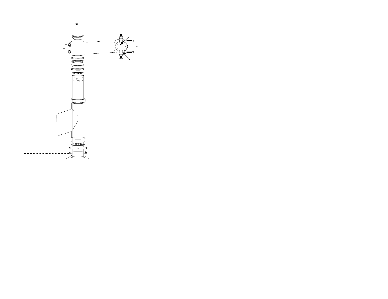
Stem Installation (should be assembled on the bike already)
1. Insert the compression bolt through the top cap and the stem. Begin
threading into the star nut.
2. Tighten compression bolt so it removes all play from the fork, but allows
the fork to rotate smoothly.
3. Align the stem with the front wheel. Tighten the stem clamp bolts to
secure the stem to the steering tube.
Handlebar Installation
1. Remove the stem cap bolts and stem cap.
2. Insert handlebar into the stem cap.
3. Tighten the stem cap bolts equally. Note the distance between the stem and
stem cap "A" should be equal on the top and bottom of the stem cap
.
Wedge
Head Tube
Compression Bolt
Top Cap
Stem Clamp Bolts
Spacer
Bearing Race
Bering Retainer
Upper Headset Cup
Bearing Retainer
Headset Wedge
Bearing Dust Cover
Star Nut
(Inside Steerer Tube)
Headtube
Lower Headset Cup
Bearing Dust Cover
Headset Crown Race
Installed
By
Factory
Handlebar
Stem
Cap
Bolts
Stem Cap
17
!
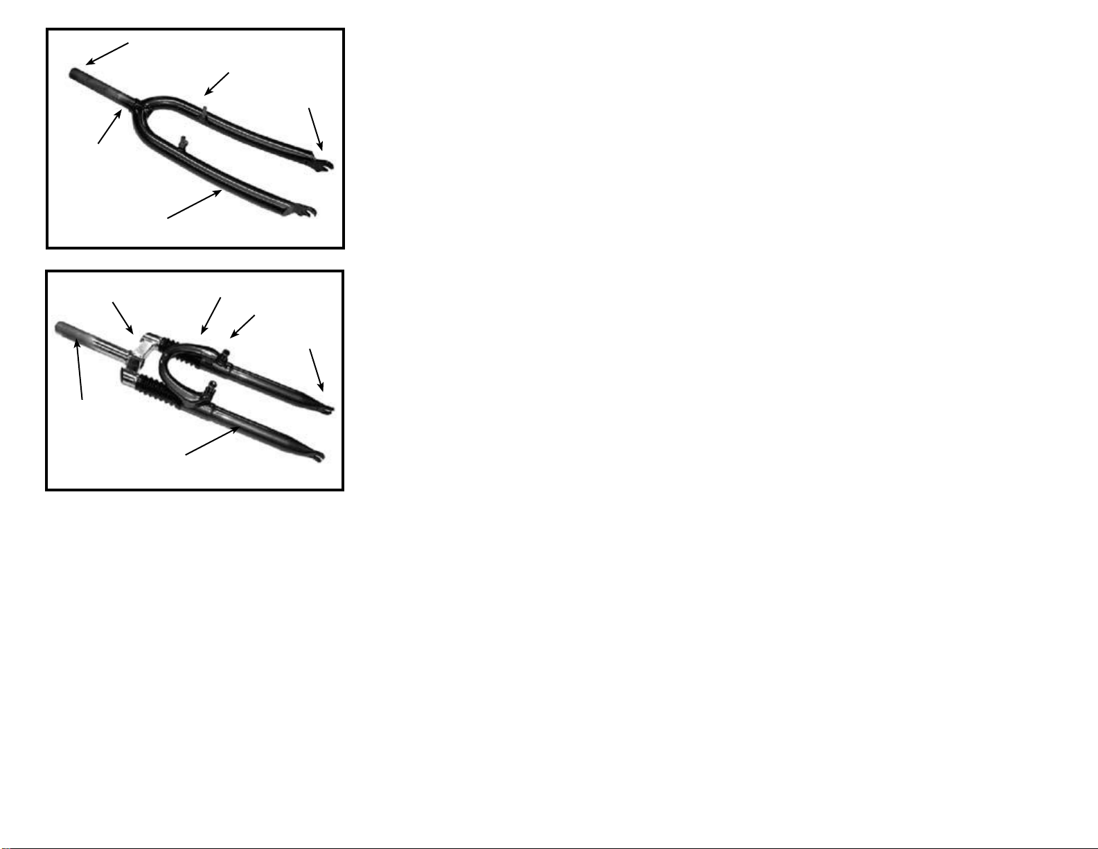
Forks
There are two different types of forks that vary in styles and dimensions. One type is a rigid
fork (Figure 1) consisting of stationary tubing with curved blades. The other type is a
suspension fork (Figure 2) consisting of inner stanchion tubes riding on elastomers or springs
inside of a straight outer fork leg. This mechanism acts as a shock absorber with a specified
amount of travel that varies between models. Some suspension forks are not adjustable and
are very difficult to disassemble. If service is needed on a suspension fork, consult a
professional bicycle repair technician
Your bicycle is equipped with a Suspension Fork as shown in figure 2
Do not attempt to disassemble a suspension fork yourself.
Consult
X-Treme Scooters for assistance
.
If your bike is equipped with a suspension fork, check that the fork compresses and rebounds
smoothly. To do this, place the fork dropouts against the ground, push and release the handle-
bar. The fork will generally compress 1-2” and rebound quickly. Most elastomer type forks
will gradually soften with use.
Fork

18
SEAT AND SEAT
P
OST
Your bicycle may come equipped with either a standard or a micro-adjustable seat post.
Standard
s
eat post
Attach the seat to the seat post by first loosening the nuts on the seat clamp. Insert the tapered
end of the seat post into the seat clamp until it is at the top of the clamp. Partially tighten the
nuts on the seat clamp, then insert the seat assembly into the frame of the bicycle and adjust the
seat to the proper height. The seat post must be inserted to at leastthe “Minimum Insertion” line.
Move the quick release
lever to the closed position. You should feel considerable resistance while moving the lever. If not, re-open and tighten the lever, then move it to the closed
position. See the section in this manual regarding quick releases for more detailed instructions. Adjust the seat to be centered in the clamp and generally
level with the ground, then re-tighten the clamp nuts evenly before riding. Avoid riding the bike with a loose saddle.
Micro-
a
djustable
s
eat post
Loosen the seat fixing bolt, then slide the seat into the clamp. The two seat rails should fit into the corresponding channels
in the clamp. There is usually no need to completely remove the fixing bolt, but it may be necessary in some cases. Partially tighten the seat fixing bolt, then
insert the seat assembly into the frame of the bicycle and adjust the seat to the proper height. The seat post must be inserted to at least the “Minimum
Insertion” line. Move the quick release lever to the closed position.
You should feel considerable resistance while moving the lever. If not, re-open and tighten the lever, then move it to the closed position. See the section in
this manual regarding quick releases for more detailed instructions. Adjust the seat to be centered in the clamp and generally level with the ground, then
re-tighten the seat fixing bolt before riding. Avoid riding the bike with a loose saddle.
NOTE: Some models of bicycles may be equipped with a suspension seat post. Some suspension posts can be adjusted for stiffness using the preload adjusting
screw. Turning the 6mm Allen screw Clockwise will make the suspension stiffer, while turning the 6mm Allen screw Counter-clockwise will make the
suspension softer.
The seat post must be inserted so that the minimum insertion mark cannot be seen. The quick release mechanism must be tightened securely to
prevent a sudden shift of the seat when riding. Failure to do this may cause loss of bicycle control.
Seat Fixing Bolt
Quick Release
Lever
Micro-Adjustable
Seat Post
Seat Clamp Nuts
Seat Clamp Post
19
Figure 2
Figure 1 Figure 3
Figure 4 Figure 5
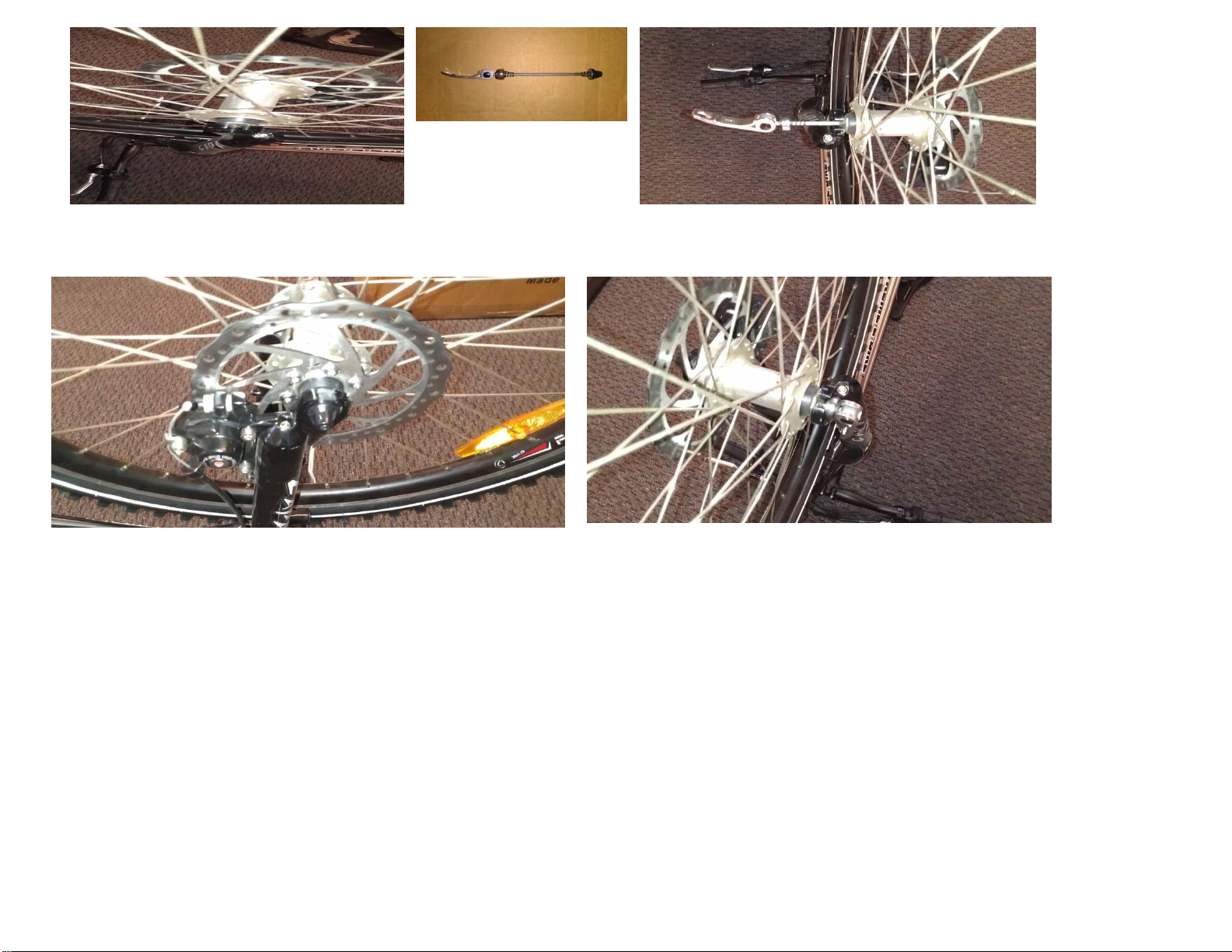
INSTALLING THE FRONT WHEEL
1. Make sure the brakes are loose enough to allow the brake pads easily.
2. Place wheel into fork drop outs (Figure 1).
3. Insert Quick ReleaseAxle (Figure 2) as shown in Figure 3 & 4 with nut.
4. When axle is in place, push lever down on axle to lock into place (Figure 5).
5. Spin the wheel to make sure it is centered and clears the brake shoes. Tighten brakes if necessary.
**IMPORTANT**
It is very important to check the front wheel connection to the bicycle. Failure to properly tighten may cause the front wheel to dislodge.
This manual suits for next models
1
Table of contents
Other Xtreme Scooter manuals

Xtreme
Xtreme X-010 User manual

Xtreme
Xtreme X-500 User manual

Xtreme
Xtreme XM-3150 Troubleshooting guide

Xtreme
Xtreme X-360 User manual

Xtreme
Xtreme X-600 User manual

Xtreme
Xtreme XG-575DS User manual

Xtreme
Xtreme XMB-320 User manual

Xtreme
Xtreme XMB-400 User manual

Xtreme
Xtreme XM-3000 Troubleshooting guide

Xtreme
Xtreme XB-700Li User manual

Xtreme
Xtreme XM-3100 Troubleshooting guide

Xtreme
Xtreme X-360 User manual

Xtreme
Xtreme XH-505 User manual

Xtreme
Xtreme X-360 User manual

Xtreme
Xtreme XB-300SLA User manual

Xtreme
Xtreme XP-707 User manual

Xtreme
Xtreme XB-420M User manual

Xtreme
Xtreme XR-301 User manual

Xtreme
Xtreme XG-550 User manual

Xtreme
Xtreme X-160 User manual


