Xvent MiracleAir 300-A1 Operation manual

1
Version 1
–
GBR
(05/05/2020)
D
-
502
-
0
173
INSTRUCTIONS FOR USE AND INSTALLATION OF MIRACLEAIR
EXTRACTION AND FILTRATION UNITS

2
Version 1
–
GBR
(05/05/2020)
D
-
502
-
0
173
CONTENT
1. General information ................................................................................................................................................................... 4
1.1. Introduction ....................................................................................................................................................................... 4
1.2. Warnings and symbols .................................................................................................................................................. 4
1.3. Using the unit .................................................................................................................................................................... 4
1.3.1. Intended use of the unit ........................................................................................................................................... 4
1.3.2. Prohibited use of the unit – MiracleAir unit must not be used: ............................................................................... 5
1.4. Transportation, delivery inspection and storage .............................................................................................................. 5
1.4.1. Transportation .......................................................................................................................................................... 5
1.4.2. Delivery inspection ................................................................................................................................................... 5
1.4.3. Storage ...................................................................................................................................................................... 5
1.5. Package contents ............................................................................................................................................................... 5
1.6. Before the installation ....................................................................................................................................................... 5
2. Technical parameters ................................................................................................................................................................. 6
2.1. MiracleAir unit design ....................................................................................................................................................... 6
2.1.1. Aerosol extraction unit with a special arm MiracleAir 300-A1 ................................................................................. 6
2.1.1.1. Arm (positions 1 and 2) ........................................................................................................................................ 7
2.1.1.2. Extraction box (position 3) ................................................................................................................................... 7
2.1.1.3. Filter box (position 4) ........................................................................................................................................... 7
2.1.1.4. Design side panels (position 5) ............................................................................................................................. 7
2.1.1.5. Fan box with control panel (position 6) ............................................................................................................... 7
2.1.1.6. Main switch (position 7.) ...................................................................................................................................... 7
2.1.1.7. Power cable with plug (position 8.) ...................................................................................................................... 7
2.1.2. Air purifier - MiracleAir 400-B unit ........................................................................................................................... 7
2.1.2.2. Filtration box ........................................................................................................................................................ 8
2.1.2.3. Design side panels ................................................................................................................................................ 8
2.1.2.4. Fan box with control panel ................................................................................................................................... 8
2.1.2.5. Main switch (position 7.) ...................................................................................................................................... 8
2.1.2.6. Power cable with plug (position 8.) ...................................................................................................................... 8
2.2. Main dimensions of Miracleair aerosol extraction unit and the air purifier ..................................................................... 8
2.2.1. MiracleAir 300-A1 aerosol extraction unit ............................................................................................................... 8
2.2.2. Air purifier - MiracleAir 400-B unit ........................................................................................................................... 9
2.3. Technical parameters of MiracleAir 300-A1 units; MiracleAir 400-B ................................................................................ 9
3. Unit installation .......................................................................................................................................................................... 9
3.1. General information, recommendations and safety when installing MiracleAir unit ....................................................... 9
3.1.1. Electrical safety before unit installation ................................................................................................................... 9
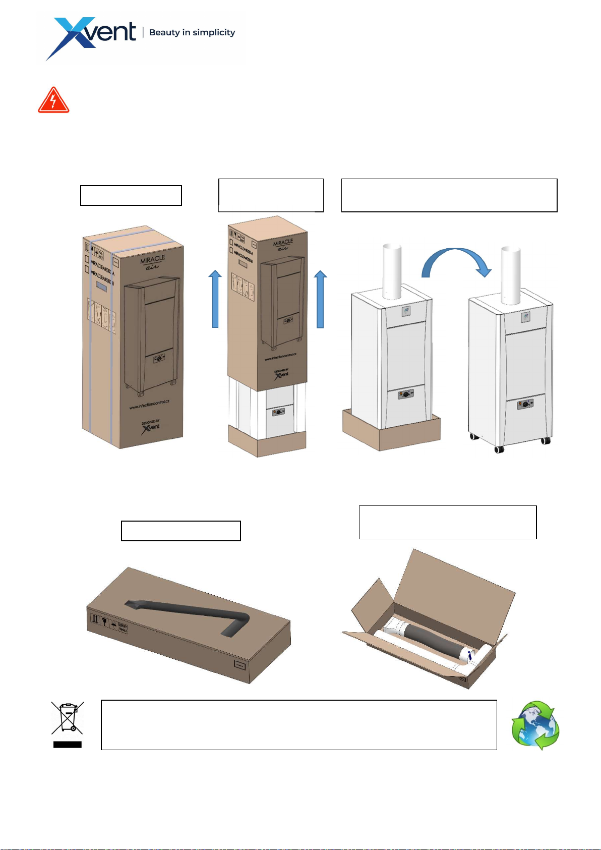
3.1.2. Unpacking ............................................................................................................................................................... 10
3.1.2.1. Unpacking the MiracleAir Unit - box 1 ............................................................................................................... 10
3.1.2.2. Unpacking the suction arm - box 2 (only in the case of the MiracleAir 300-A1 aerosol extractor) ........................ 10
3.1.3. Positioning of the unit ............................................................................................................................................ 11
3.1.4. Minimum installation distances.............................................................................................................................. 11

3
Version 1
–
GBR
(05/05/2020)
D
-
502
-
0
173
3.1.4.1. MiracleAir 300-A aerosol extraction unit ........................................................................................................... 11
3.1.4.2. Air purifier - MiracleAir 400-B unit ..................................................................................................................... 11
3.2. Installation of the MiracleAir unit ................................................................................................................................... 11
3.2.1. Installation of the MiracleAir 300-A aerosol extraction unit .................................................................................. 11
3.2.1.1. Assembling the exhaust arm .............................................................................................................................. 11
3.2.2. Installation of a protective sleeve .......................................................................................................................... 12
3.2.3. Installation of air purifier - MiracleAir 400-B units ................................................................................................. 13
3.3. Electrical installation - connection to the electrical network .......................................................................................... 13
3.3.1. General information - safety .................................................................................................................................. 13
3.3.2. Mains connection ................................................................................................................................................... 13
3.3.3. Labelling of electrical parameters .......................................................................................................................... 13
4. Regulation - unit control ........................................................................................................................................................... 14
4.1. General information - safety ........................................................................................................................................... 14
4.2. Controls ........................................................................................................................................................................... 14
4.2.1. Main control panel ................................................................................................................................................. 14
4.2.1.1. Main control - knob (position 1)......................................................................................................................... 14
4.2.1.2. Signal diode ........................................................................................................................................................ 14
4.2.1.3. Indicator of filter box clogging - signalisation of need for filter box replacement ............................................. 14
5. Wiring diagram of MiracleAir units .......................................................................................................................................... 15
6. Commissioning ......................................................................................................................................................................... 16
6.1. Before the first operation, check the following: ............................................................................................................. 16
6.2. Switching on .................................................................................................................................................................... 16
6.3. Setting the correct power of the unit .............................................................................................................................. 16
6.3.1. Setting the output of the MiracleAir 300-A aerosol exhaust .................................................................................. 16
6.3.2. Setting the output for the air purifier - MiracleAir 400-B unit ............................................................................... 17
7. Regular maintenance and cleaning of Miracleair units ............................................................................................................ 17
7.1. Regular maintenance – inspection .................................................................................................................................. 17
7.1.1. General information ............................................................................................................................................... 17
7.1.2. Filter box replacement ............................................................................................................................................ 18
7.1.3. Replacement of protective sleeve (only for the version with suction arm) ........................................................... 24
7.2. Cleaning the unit ............................................................................................................................................................. 24
7.2.1. General information ............................................................................................................................................... 24
7.2.2. Cleanable surfaces .................................................................................................................................................. 24
8. Service ...................................................................................................................................................................................... 24
8.1. Troubleshooting .............................................................................................................................................................. 25
8.2. Error persists ................................................................................................................................................................... 25
9. Decommissioning, dismantling and recycling ........................................................................................................................... 25
10. Warranty .............................................................................................................................................................................. 26
11. In conclusion ........................................................................................................................................................................ 26

4
Version 1
–
GBR
(05/05/2020)
D
-
502
-
0
173
1. General information
1.1. Introduction
- This document "Installation and Instructions for Use" (IFU) is intended for MiracleAir 300-A extraction
unit and MiracleAir 400-B filter unit (hereinafter referred to as the unit) intended to extract and filter
indoor air in required spaces. The extraction and filtration unit is used to remove particles directly at the
place of their origin to protect the health of workers.
- Detailed knowledge of this document is important for correct and safe installation and operation of the
unit. Failure to follow the terms in this document may result in malfunction of the unit.
- Keep the IFU of the unit for future reference after thoroughly reading it.
- It is forbidden to interfere with the internal wiring of the unit in any other way than specified in this
manual. Due to the constant development of our products, we reserve the right to change this manual
without prior notice.
1.2. Warnings and symbols
- The following names and symbols are used in the IFU, on the packaging and on the product for particularly
important information:
Warning
Caution, risk of electric shock
Connection of protective conductor
Indicates the correct position when handling and storing the packaging
Cautions about the need for protection against moisture. Product - packaging labelled with this symbol
may not be transported in open vehicles and stored in uncovered buildings and on the ground without a
pad
Draws attention to the fragility of the product contents and need for careful handling of the packaged
product.
Draws attention to the need for protection against moisture and the fragility of the product inside the
packaging
Orientation arrow for filter placement
1.3. Using the unit
1.3.1. Intended use of the unit
- MiracleAir unit is intended for indoor use only, without dust over-saturation in the surrounding air to:
o extraction of aerosol-smoke, which may be generated during medical procedures in association
with the treatment of the patient, e.g.: dental treatment, anaesthesiology management, etc.
o indoor air filtration e.g.: medical facilities, waiting rooms, cosmetic facilities, offices, etc.
- The unit is designed for the extraction and filtration of particles larger than 0.1 to 0.3 µm (filtration
efficiency of 99.95%).
- The unit is designed for indoor use in covered and dry areas with an ambient temperature from 5° C to
+40° C and with a maximum relative humidity of 70% (non-condensing).

5
Version 1
–
GBR
(05/05/2020)
D
-
502
-
0
173
1.3.2. Prohibited use of the unit – MiracleAir unit must not be used:
- for extracting burning or glowing substances!
- to extract highly flammable or explosive gases.
- for extracting aggressive media
- for extracting liquids of any kind.
- in an environment with an increased risk of explosion, flammable substances and increased dust load.
- Neither the manufacturer nor the supplier is liable for damages caused by improper use of the units. The
risk is borne by the user.
1.4. Transportation, delivery inspection and storage
1.4.1. Transportation
- Transport the product in the position marked with the symbol on the packaging.
- The packaging must not be loaded in excess of limits permitted by the manufacturer.
- The packaging must not be exposed to environmental effects
- The transport temperature of the air must be between –25 and 55° C, for a short time (24h) up to 70° C.
- The relative humidity during the transport must be between 10 and 90% (non-condensing).
- Use adequate tools for transport to prevent damage to the product and damage to the health and
endangering persons.
- During further transport without the original packaging or with altered original packaging, the device
must be optimally secured and protected against damage.
1.4.2. Delivery inspection
- Before the installation and before unpacking the unit from the box, it is necessary to check the packaging
for any signs of damage. In case of damage to the packaging, please contact your carrier.
- Check that the delivery truly contains the product you ordered. After unpacking, check that the unit and
other components are not damaged. Report any discrepancy with the ordered products immediately to
the supplier. If the complaint is not made immediately after the delivery, it will not be taken into account
later.
1.4.3. Storage
- If you do not install the unit immediately after the purchase, it must be stored indoor, in non-condensing
environment at temperatures ranging from 0 to 40° C. If the product is transported at temperatures
below 0° C, it must be stored in the operating environment it is to be installed for at least 2 hours after
unpacking.
1.5. Package contents
Box 1
- MiracleAir unit 1x
- Quick manual + safety data sheet 1x
- Production label 1x
Box 2 (only for units with a suction arm)
- Suction arm 1 (fixed) 1x
- Suction arm 2 (with flexible end) 1x
- Mounting clip 2x
- Self-tapping screw 4.2x9.5 2x
- Protective sleeve 50x
1.6. Before the installation
- Before the installation, we recommend attaching the production label (supplied in the package) to the
operating documentation (e.g. equipment operation book, etc.) to be kept for later maintenance records
and possible service.
- Before starting any installation work, make sure that the intended mains socket is equipped with a
protective contact (pin).
- Verify that the outlet meets power requirements of the unit (voltage, current, etc.) listed on the
production plate of the unit.

6
Version 1
–
GBR
(05/05/2020)
D
-
502
-
0
173
Fig. 1
2. Technical parameters
2.1. MiracleAir unit design
2.1.1. Aerosol extraction unit with a special arm MiracleAir 300-A1
1. ARM 1 (fixed)
2. ARM 2 (with flexible end)
3. EXTRACTION BOX
4. FILTRATION BOX
(COARSE PARTICULATE FILTER + PREFILTER + HEPA
FILTER + FILTER WITH ACTIVATED CARBON)
5. DESIGN SIDE PANELS (2 PCS)
2
1
4
6
6. FAN BOX WITH CONTROL PANEL
7. MAIN SWITCH
8. POWER CABLE WITH PLUG
7
8
3
5

7
Version 1
–
GBR
(05/05/2020)
D
-
502
-
0
173
1. EXTRACTION BOX
2. FILTRATION BOX
(COARSE PARTICULATE FILTER + PREFILTER + HEPA
FILTER + FILTER WITH ACTIVATED CARBON)
3. DESIGN SIDE PANELS (2 PCS)
4. FAN BOX WITH CONTROL PANEL
Fig. 2
2.1.1.1. Arm (positions 1 and 2)
- Swivel arm with flexible end terminated by a suction nozzle. Arm material – PVC and ABS plastic. The arm
is fully cleanable.
2.1.1.2. Extraction box (position 3)
- 1-mm thick sheet steel construction treated with RAL 9003 anti-corrosion powder paint and protective
varnish to increase resistance to disinfection products
2.1.1.3. Filter box (position 4)
- 1-mm thick sheet steel construction treated with RAL 9003 anti-corrosion powder paint and protective
varnish to increase resistance to disinfection products Equipped with filters from the factory: Stage 1 -
class G1 coarse particle filter; filtration stage 2 - pre-filter class F7 (ISO ePM1 65%, ISO ePM2.5 95%);
filtration stage 3 - HEPA H13 (ISO ePM1 99.95%); filtration stage 4 - activated carbon filter to remove
odours
2.1.1.4. Design side panels (position 5)
- 1-mm thick sheet steel construction treated with RAL 9003 anti-corrosion powder paint and protective
varnish to increase resistance to disinfection products
2.1.1.5. Fan box with control panel (position 6)
- 1-mm thick sheet steel construction treated with RAL 9003 anti-corrosion powder paint and protective
varnish to increase resistance to disinfection products The box contains a fan, regulation unit, manometer
for measuring filter clogging.
2.1.1.6. Main switch (position 7.)
- main 1-pole "rocker" switch with position symbols: ON I, OFF 0; intended to disconnect the unit from the
power supply.
2.1.1.7. Power cable with plug (position 8.)
- flex cord type cable (with integrated plug) 3x1mm2, material PVC
2.1.2. Air purifier - MiracleAir 400-B unit
5. MAIN SWITCH
6. POWER CABLE WITH PLUG
1
2
4
3
6
5

8
Version 1
–
GBR
(05/05/2020)
D
-
502
-
0
173
Fig. 3
2.1.2.1. Extraction box (position 1)
- 1-mm thick sheet steel construction treated with RAL 9003 anti-corrosion powder paint and protective
varnish to increase resistance to disinfection products
2.1.2.2. Filtration box
- 1-mm thick sheet steel construction treated with RAL 9003 anti-corrosion powder paint and protective
varnish to increase resistance to disinfection products Equipped with filters from the factory: Stage 1 -
class G1 coarse particle filter; filtration stage 2 - pre-filter class F7 (ISO ePM1 65%, ISO ePM2.5 95%);
filtration stage 3 - HEPA H13 (ISO ePM1 99.95%); filtration stage 4 - activated carbon filter to remove
odours
2.1.2.3. Design side panels
- 1-mm thick sheet steel construction treated with RAL 9003 anti-corrosion powder paint and protective
varnish to increase resistance to disinfection products
2.1.2.4. Fan box with control panel
- 1-mm thick sheet steel construction treated with RAL 9003 anti-corrosion powder paint and protective
varnish to increase resistance to disinfection products The box contains a fan, regulation unit, manometer
for measuring filter clogging.
2.1.2.5. Main switch (position 7.)
- main 1-pole "rocker" switch with position symbols: ON I, OFF 0; intended to disconnect the unit from the
power supply.
2.1.2.6. Power cable with plug (position 8.)
- flex cord type cable (with integrated plug) 3x1mm2, material PVC
2.2. Main dimensions of Miracleair aerosol extraction unit and the air purifier
2.2.1. MiracleAir 300-A1 aerosol extraction unit

9
Version 1
–
GBR
(05/05/2020)
D
-
502
-
0
173
Fig. 4
2.2.2. Air purifier - MiracleAir 400-B unit
2.3. Technical parameters of MiracleAir 300-A1 units; MiracleAir 400-B
- EC Declaration of Conformity - current and full version of the EC Declaration of Conformity is available on
our website www.xvent.cz in the MiracleAir product documents
3. Unit installation
3.1. General information, recommendations and safety when installing MiracleAir unit
3.1.1. Electrical safety before unit installation
- Before starting any installation work, make sure that the intended mains socket is equipped with a
protective contact (pin).

10
Version 1
–
GBR
(05/05/2020)
D
-
502
-
0
173
Please dispose of all the unnecessary packaging via
appropriate recycling points,
where they will be professionally handled. Only packaging recycled in this way can be
reused properly and returned to circulation.
Fig. 5
Fig. 6
- The mains plug must always remain accessible
- Verify that the outlet meets power requirements of the unit (voltage, current, etc.) listed on the
production plate of the unit.
3.1.2. Unpacking
3.1.2.1. Unpacking the MiracleAir Unit - box 1
- always unpack the unit in a space large enough to allow for removing the unit from the package.
- Proceed as follows:
3.1.2.2. Unpacking the suction arm - box 2 (only in the case of the MiracleAir 300-A1 aerosol extractor)
- Remove the suction arm from the top box as follows:
CUT THE TAPES
SLIDE THE BOX UP
REMOVE THE PACKAGING MATERIAL AND
REMOVE THE UNIT FROM THE LOWER BOX
OPEN THE BOX
UNPACK THE COMPONENTS OF
THE ARM

11
Version 1
–
GBR
(05/05/2020)
D
-
502
-
0
173
Fig. 7
3.1.3. Positioning of the unit
- Place the device on a clean, level, cohesive and dust-free floor.
- Observe the ambient conditions specified in the chapter 1.3.1 – intended use of the unit
- Consider the location for the exhaust air from the bottom of the unit to avoid discomfort during the
operation.
- Once in place, always secure the unit against unintentional movement using the wheel brakes (step-down).
3.1.4. Minimum installation distances
3.1.4.1. MiracleAir 300-A aerosol extraction unit
- No minimum distance of the unit body from walls or solid obstacles is specified.
- The minimum distance of the exhaust in the bottom of the unit (under the fan box) from walls or solid
obstacles is at least 0.2 m. Failure to observe this distance may result in improper operation of the unit
and the damage to the fan or increased noise level of the unit.
- The minimum distance of the suction nozzle from the extraction space is not specified. However, the
recommended minimum distance is 0.15 m.
- Consider the fact that vacuum is generated in the suction nozzle, which can result in unwanted objects
being sucked in (e.g. sterile tampons, cellulose etc.)
3.1.4.2. Air purifier - MiracleAir 400-B unit
- The minimum distance of the unit from the wall or fixed obstacles is 0.2 m. Failure to observe this distance
may result in improper operation of the unit and the damage to the fan or increased noise level of the unit.
3.2. Installation of the MiracleAir unit
3.2.1. Installation of the MiracleAir 300-A aerosol extraction unit
3.2.1.1. Assembling the exhaust arm
- prepare a Phillips screwdriver to assemble the arm
- make sure there is enough space to fold the arm - on the table, on the floor
- slide the arm 1 (fixed) onto the arm 2 (with flexible end) so that the ends of the arms marked with blue
circles are oriented towards each other

12
Version 1
–
GBR
(05/05/2020)
D
-
502
-
0
173
Fig. 8
Fig. 9
Fig. 10
- fasten the arms using self-tapping screws 4, 2x9 (included in the arm package) into the pre-made hole on
each side of the tubed.
- use appropriate force when tightening the screws to prevent damage to the arm tube
- fastening must be done thoroughly to prevent the arm from accidentally disconnecting and resulting
damage to the arm and additional possible damage to property or injuries.
- slide the assembled arm into the tube mounted on the unit
- check the function of the arm by turning it into any position. Subsequently, check the positioning
functionality of the flexible arm end by setting into any position. In case of need to extend the flexible
part of the arm, pull at it to extend it by approx. 15 cm. Turning, positioning, and extending of the arm
should be possible without using excessive force.
3.2.2. Installation of a protective sleeve
- The sleeve is disposable and is used for easier disinfection of the exhaust arm.
- To pull the protective sleeve on the unit, follow this procedure:
a) Unwind and tear the protective sleeve from the supplied package
b) Slide the protective slide on the exhaust arm in the direction away from the exhaust nozzle and
secure it using a clamping clip (included in the package) on each end of the arm.

13
Version 1
–
GBR
(05/05/2020)
D
-
502
-
0
173
3.2.3. Installation of air purifier - MiracleAir 400-B units
- No further installation is required after unpacking and positioning Miracleair filter unit.
3.3. Electrical installation - connection to the electrical network
3.3.1. General information - safety
- Before starting the installation, make sure that the mains socket you intend to use to connect the unit
is equipped with a protective contact (pin).
- The mains plug must always remain accessible so that the unit may be safely disconnected from the
mains in the event of danger.
- Verify that the outlet meets power requirements of the unit (voltage, current, frequency etc.) listed on
the production plate of the unit.
- The relevant circuit must be protected in the power supply to maximum of 16 A.
- The mains cable must not be broken.
- Local electrical regulations must always be observed
- When handling the unit, disconnect the device from the mains first (pull out the mains socket)
- It is forbidden to tamper with the internal wiring of the unit in any way
- This unit belongs to the product group with type Y connection. If the mains cable is damaged, it must
be replaced by the manufacturer, its service agent or similarly qualified persons in order to avoid a
high-risk situations.
- The supply voltage to the fan 1~230V / 50-60Hz must not be altered in any way. Otherwise there is a
risk of damage to the unit fan.
3.3.2. Mains connection
- the unit is supplied with a power supply cable with a flex plug with a protective contact. The length of the
mains cable is 2.7 m.
- The unit is equipped with a 1-pole mains switch, which can be used to switch the power supply on and
off.
- Connecting the unit to the mains does not require any further electrical connections, interconnections.
3.3.3. Labelling of electrical parameters
- all electrical parameters of the unit are shown on the production label
Fig. 11
Type: product type
Voltage (U): XXX V AC Frequency (f): XX/XX Hz
Current (I): XXX A Weight (m): XX kg
Input (P): XXX W IP: XX
Serial number
MADE IN CZECH REPUBLIC
EAN of the product

14
Version 1
–
GBR
(05/05/2020)
D
-
502
-
0
173
4. Regulation - unit control
4.1. General information - safety
- Regulation is integrated into the body of the unit. Any manipulation other than specified in this manual
is prohibited.
- All control elements located on the body of the unit, which are designed for user control, are powered
by 10VDC (safe voltage).
4.2. Controls
4.2.1. Main control panel
4.2.1.1. Main control - knob (position 1)
- The main control (know) allows for continuous adjustment of the power of the unit in any position from
the minimum to maximum power according to the user's requirements.
- The "OFF" position switches the entire unit off.
- The "OFF" position does not disconnect the unit from the power supply (the unit may be disconnected
from the mains using the main switch located on the back of the unit or by unplugging the power cord
from the power outlet)
4.2.1.2. Signal diode
- Indicates operation of the unit. If the LED is ON, the unit is active. If it is not lit, the unit is turned off
4.2.1.3. Indicator of filter box clogging - signalisation of need for filter box replacement
- The orange indicator activates when the filter box is clogged. At the same time, it informs the user about
the need to replace the filter box (box replacement is described in the chapter 7.1.2. filter box
replacement).
- The indicator activates automatically depending on the current, actual clogging of the filter box, which is
set by the manufacturer.
- One of the parameters that affect the activation of the indicator is also power-flow the whole unit is
operated at. In general, the smaller the power-flow of the unit, the longer the time for indicator activation
(the less air is filtered).
1. MAIN CONTROL (KNOB)
2. SIGNAL LED
3. FILTER CLOGGING WARNING INDICATOR
1
2
3
Fig. 12

15
Version 1
–
GBR
(05/05/2020)
D
-
502
-
0
173
5. Wiring diagram of MiracleAir units
- internal wiring diagram of the unit
Fig. 14

16
Version 1
–
GBR
(05/05/2020)
D
-
502
-
0
173
6. Commissioning
6.1. Before the first operation, check the following:
- All fixation elements used during transport have been removed
- The mains cable of the unit is properly connected to the mains
6.2. Switching on
- Turn the main power switch at the back of the unit from the position 0 to the position I
- Turn the main control element (knob) to approximately central position of the output scale (vertical)
- A blue signal diode on main control panel will light up, signalling the unit is running
- The unit will start increasing output to the set value. Unit fan start-up can take approx. 5 sec.
- Set the arm to the supposed operating position. If necessary, the arm may be extended by 15 cm in the
flexible part to increase its reach.
- Use adequate force when adjusting the arm to the desired position to avoid damage to the arm or tipping
the unit over.
- After starting the unit for the first time, check the basic performance of the unit
6.3. Setting the correct power of the unit
6.3.1. Setting the output of the MiracleAir 300-A aerosol exhaust
- The setting of the effective extraction power is displayed on the scale of the main control (know) by the
symbol of the suction arm; effective extraction power is marked
in dark colour.
MINIMUM RECOMMENDED
OUTPUT SETTING OF THE
EXHAUST UNIT – EFFECTIVE
EXTRACTION DISTANCE approx. 20
cm
MAXIMUM RECOMMENDED
OUTPUT SETTING OF THE
EXHAUST UNIT – EFFECTIVE
EXTRACTION DISTANCE approx. 30
cm
Fig. 15

17
Version 1
–
GBR
(05/05/2020)
D
-
502
-
0
173
6.3.2. Setting the output for the air purifier - MiracleAir 400-B unit
- Use the main control (know) to adjust the filtration performance in the entire range of the scale.
- To select the desired performance for your filter unit, always consider the space it will operate in.
- Select the appropriate unit output based on area of the space to be filtered.
7. Regular maintenance and cleaning of Miracleair units
- Before any maintenance and cleaning of the unit, the unit must be disconnected from the power
supply – unplug the mains cable.
7.1. Regular maintenance – inspection
7.1.1. General information
- Perform a regular visual inspection of particulate filter clogging (top filter in the filter box). The filter also
captures inadvertently sucked components, which can significantly reduce the extraction power of the
unit.
- Always perform the regular inspection of the unit when replacing a dirty - old filter box with a new one.
Filter replacement is described in a separate chapter 7.1.2.
1
.
3
.
.5
Fig. 16

18
Version 1
–
GBR
(05/05/2020)
D
-
502
-
0
173
- If the unit does not require the replacement of filters more often than once a year, the unit must be
inspected regularly, at a maximum interval of once every 12 months or at intervals determined by the
relevant national regulations or practices.
- If the unit is not used for longer time, it is necessary to turn off the supply voltage to the unit.
- Service work beyond normal maintenance may only be performed by the manufacturer.
- Regular maintenance must include:
o Visual inspection of the unit housing, mechanical components
o Visual inspection of the arm, in particular the locking screws
o Visual inspection of the mains cable
o Check that the pressure measuring hose is correctly connected at the pressure coupling and at
the measuring points.
o Check that the pressure caps are tightened correctly – they must not be loose. If necessary, the
cap must be opened – then tighten the clip by 1 turn (360°) and then re-tighten it. Always tighten
the pressure caps one at a time.
- The unit is designed and manufactured so that it does not require any special maintenance
7.1.2. Filter box replacement
- The filter box may contain dust particles, bacteria and viruses, so it is necessary to use appropriate
protective equipment to prevent contamination or contact with harmful substances. When carrying
out any work with the filter box, we recommend to use at least disposable polypropylene gloves and a
fine dust protective mask (protection level 3).
- The need for replacement of the filter box is indicated on the main control panel by the orange indicator
for filter box clogging
- The indicator activates whenever the filter box is clogged as set by the manufacturer.
Fig. 17

19
Version 1
–
GBR
(05/05/2020)
D
-
502
-
0
173
- Clogging of the filter box and subsequent activation of the indicator depends on the environment where
the unit operates. In particular on:
o Ambient air dust load - the more dust particles are in the air, the sooner the filter box becomes
clogged
o Operating power of the unit - the more air the unit filters, the sooner the filter box becomes
clogged
- After the light comes on, immediately replace the filter box with a new one, as follows:
a) Switch off the unit using the main control (knob) to the OFF position and the main switch from the
back of the unit to the position 0.
b) Disconnect the unit from the power supply by removing the plug of the mains cable from the socket
c) Remove the side covers from the side of the unit.
Fig. 18

20
Version 1
–
GBR
(05/05/2020)
D
-
502
-
0
173
DISCONNECTION OF THE CONNECTOR
AND THE HOSE
d) Disconnect the connectors for switch connection, earth connectors and for connectors for the hose
from the side of the unit
e) If operating the unit with a suction arm, slide the arm out and store it in a safe place to prevent damage.
DISCONNECTION OF EARTH
CONNECTOR
1. PUSHING THE
BLUE CIRCLE DOWN
2. REMOVING THE
HOSE FROM THE
CONNECTOR
DISCONNECT
BOTH
CONNECTORS FROM
THE EARTH
Fig. 19
Fig. 20
This manual suits for next models
1
Table of contents