Esta OILMAC 400 User manual

OPERATING INSTRUCTIONS
The World of Extraction
OILMAC 400
Oil Mist Extractor

Your purchase of an ESTA machine has
been a good decision. The design of
our quality products complies with the
latest state of the art. ESTA products
have been devised to provide for clean
air at the workplaces at which they are
applied. This results in an even more
enhanced level of quality and longer
machine times and, particularly, healthier
working conditions. Should you have
any questions pertaining to suction tech-
nology issues, please feel free to contact
us at any time. Our experts will be gladly
at your disposal.
Your ESTA Absaugtechnik Team
The World of Extraction
www.esta.com
Welcome to the sphere of suction
technology

Operating Instructions
OILMAC 400
with backup filter stage H13
OILMAC 400 (order o.: 56.200)
Do ot use this device u less you have
read the operati g i structio s a d u derstood them.
Origi al operati g i structio s
56200-08-07

2 OILMAC 400 56200-52-07
Edition notice
Origi al operati g i structio s
Docume t o.: 56200-08-07
Publishi g date: 11.04.2017
Type of device: OILMAC 400 Oil Mist Separator
Article o.: 56.200 a d varia ts
Publisher
ESTA Apparatebau GmbH & Co. KG Tel.: +49 (0) 73 07 80 4 -0
Gote str. 2-6 Fax: +49 (0) 73 07 80 4 -500
Germa y www.esta.com
Copyright notice (per DIN I O 16016:2007-12)
Tra sfer or reproductio of this docume t, or the use or commu icatio of its co te t, is forbidde
without explicit co se t. Violators will be liable for damages. All rights to pate t, utility or desig
registratio are reserved.

56200-52-07 OILMAC 400 3
Contents
Contents ................................................................................................................................. 3
1. General instructions ........................................................................................................ 5
1.1 Target group ......................................................................................................... 5
1.2 Tips ....................................................................................................................... 5
2 Product identification ...................................................................................................... 6
2.1 Tech ical Data ...................................................................................................... 6
2.2 I te ded applicatio .............................................................................................. 6
3 Product Description ........................................................................................................ 8
3.1 Device image ........................................................................................................ 8
3.2 Separatio a d filter eleme ts .............................................................................. 9
3.3 Fu ctio al descriptio ......................................................................................... 10
4 afety instructions ........................................................................................................ 11
4.1 Hazard categories ............................................................................................... 11
4.2 Symbol expla atio ............................................................................................. 11
4.3 Ge eral safety i structio s .................................................................................. 12
4.4 Preve ti g mecha ical hazards .......................................................................... 13
4.5 Preve ti g electrical hazards .............................................................................. 13
4.6 Preve ti g material a d substa ce hazards ....................................................... 14
5 Delivery and commissioning ........................................................................................ 15
5.1 Delivery a d tra sport ......................................................................................... 15
5.2 Co ectio .......................................................................................................... 16
5.3 Fu ctio check .................................................................................................... 20
5.4 Commissio i g ................................................................................................... 20
5.5 Troubleshooti g duri g commissio i g ............................................................... 21
6 Operating instructions .................................................................................................. 22
6.1 Operati g the device ........................................................................................... 22
7 Maintenance & troubleshooting ................................................................................... 22
7.1 Mai te a ce i structio s .................................................................................... 22
7.2 I spectio a d mai te a ce i tervals ................................................................. 24
7.3 Clea i g a d replaci g the separatio a d filter eleme ts .................................. 26
7.4 Backup filter stage filter eleme t ......................................................................... 31
7.5 Sipho co ectio mai te a ce ......................................................................... 32
7.6 Clea i g filter a d separatio eleme ts that ca be clea ed .............................. 33
7.7 Clea the device ................................................................................................. 33
7.8 Store the device .................................................................................................. 33
7.9 Troubleshooti g .................................................................................................. 34
8 Disposal ......................................................................................................................... 35
Disposi g of the separatio a d filter eleme ts ............................................................... 35
8.1 Dispose of the device .......................................................................................... 35
9 Optional equipment ....................................................................................................... 36
9.1 Start-up with pote tial-free co tact ..................................................................... 36
9.2 Set-up o adjace t sta d .................................................................................... 37
9.3 Mobile desig ...................................................................................................... 37
9.4 Saturatio display................................................................................................ 38
10 Explanations .................................................................................................................. 39
10.1 Declaratio of i corporatio for i complete machi es pursua t to EC guideli e
2006/42/EC, Appe dix II, Part 1 B ...................................................................... 39

4 OILMAC 400 56200-52-07
10.2 Declaratio of co formity for machi es pursua t to EC guideli e 2006/42/EC,
Appe dix II, Part 1 A ........................................................................................... 41
Notes ..................................................................................................................................... 42
Notes ..................................................................................................................................... 43

56200-52-07 OILMAC 400 5
1. General instructions
1.1 Target group
These i structio s are i te ded for
• Skilled warehousi g a d logistics perso el respo sible for tra sport
• Operators trai ed o the device who are familiar with the extractio process
• Service, clea i g a d mai te a ce staff trai ed o the device
• Trai ed electrical specialists
1.2 Tips
Before operatio , all perso s who are to use the device or perform mai te a ce
o it must be provided with i formatio , i structio s a d trai i g i usi g the device
a d o the substa ces for which it is to be used, i cludi g the procedure for safe
disposal of the collected material. Respo sibilities must be clearly established for
the followi g:
• Installation
• Commissioning
• Operation
• Maintenance and repairs
Read the operati g i structio s carefully before worki g with the device.
The device must be used o ly by perso s who have bee i structed i its ha dli g
a d are explicitly authorised to use it.
Always keep the operati g i structio s at the place where the device is bei g used,
so that it ca be see by perso el at all times.
These i structio s describe the device at the time of first delivery followi g ma u-
facture.
•
Keep the docume ts throughout the device's service life.
• Pass these a d other suppleme tary docume ts o to a y subseque t
ow ers or users.
• Add all cha ges to the docume ts that they obtai .

6 OILMAC 400 56200-52-07
2 Product identification
2.1 Technical Data
2.1.1 With backup filter stage H13
We reserve the right to make tech ical cha ges
Typ: OILMAC 400
Item no.
56200
Max. volume flow [m³/h] 420
Drive power [kW] 0.24 **
Co ectio voltage [V] 230 **
Nomi al freque cy [Hz] 50 **
Nomi al curre t [A] 0.9 **
Circuit breaker [A] 16 **
Protectio class IP 54
I take port ø [mm] 150
Dime sio s (L x W x H) [mm] 650 x 650 x 500
Average sou d pressure level LpA [dBA] 66
Weight [kg] approx. 50
Productio year See model plate
* usi g the e velopi g surface method DIN EN ISO 3744, measured at mi imum volume flow; oise measureme t margi
of error approx. 4 dBA
** Custom voltage o request
2.2 Intended application
2.2.1 Ambient conditions
Ambie t temperature [°C] +5 ≤ ϑ ≤ +40
Rel. humidity [%] 30 - 70

56200-52-07 OILMAC 400 7
2.2.2 Intended use
The device has bee ma ufactured based o state-of-the-art tech ology a d ac-
cordi g to recog ized safety regulatio s a d must be used as i te ded:
• For commercial use, such as i i dustrial e terprises a d workshops.
• for the separatio of aerosols (e.g. cooli g lubrica t) which arise duri g the
mecha ical processi g of metallic parts.
• for i stallatio o a processi g machi e.
• approved for air recirculatio operatio with backup filter stage H13.
Other applicatio s are co sidered u i te ded use. ESTA is ot liable for damages
due to u i te ded use!
The ma ufacturer sets up the device accordi g to the operator’s i formatio .
2.2.3 Improper use
The device has bee ma ufactured accordi g to the state of the art a d recog ized
safety regulatio s. U i te ded use may cause hazards.
Therefore:
• Do not use or store outdoors.
• Do not cha ge the locatio of the device duri g suctio operatio .
• Do not set up or operate i dust/gas-explosive areas.
• Do not use i pai ti g operatio s.
• Do not use i food operatio s.
• Do not suck up aggressive gases.
2.2.4 Reasonably foreseeable misuse
•
Do not suck up hot embers, such as cigarette butts.
• Do not cause complete closure of the suctio ports.

8 OILMAC 400 56200-52-07
3 Product Description
3.1 Device image
3.1.1 OILMAC 400
I take port
Fa u it with motor
Filter u it I let eleme t
Outlet eleme t
I spectio ope i g with
cover

56200-52-07 OILMAC 400 9
3.2 eparation and filter elements
3.2.1 Pre-filter
The separatio a d filter eleme ts are desig ed so that the air is filtered mecha -
ically through several stages of filtratio .
The pre-separator co sists of the followi g filter eleme ts:
1. Pre-filter metal mesh
2. Pre-filter fibre mat
3. Mai separator labyri th filter
1
1
2
3
2
10 OILMAC 400 56200-52-07
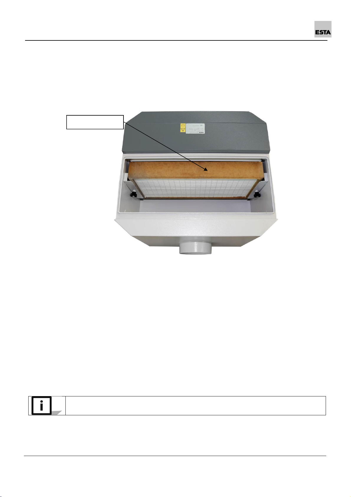
3.2.2 Backup filter stage
The separatio a d filter eleme ts are desig ed so that the air is filtered mecha -
ically through several stages of filtratio .
The backup filter is desig ed as filter stage H13:
3.3 Functional description
The device is equipped with a AC motor which drives a radial fa .
Due to the egative pressure created by the fa , air co tai i g oil a d emulsio is
draw from the processi g machi e through the suctio hose co ected to the
device's i take port. Filters located i the filter housi g reliably separate dust par-
ticles a d oil a d emulsio residue. The purified air is guided back i to the room
through the outlets at the back of the machi e.
The housi g is desig ed so that separated, fluid oil a d emulsio residue at the
bottom of the housi g accumulate a d ca be drai ed through a sipho co ec-
tio .
Separated cooli g lubrica t ca co tai impurities which could egatively affect
machi e availability i closed systems.
Backup filter
H13
56200-52-07 OILMAC 400 11
4 afety instructions
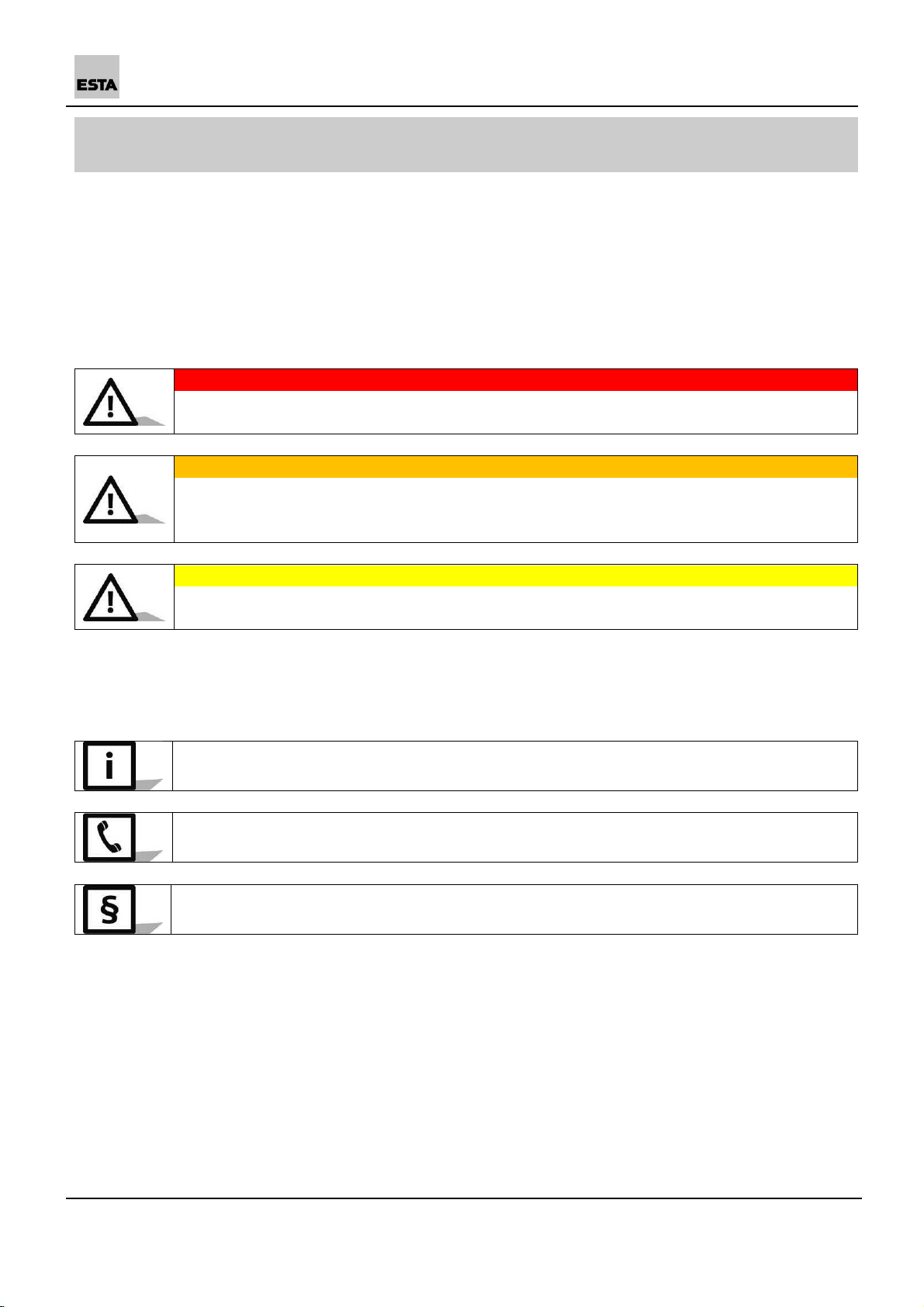
4.1 Hazard categories
Safety i structio s a d cross-topic i formatio are i dicated i this ma ual by sym-
bols.
Based o the severity of the hazard, the hazard war i gs are categorized as fol-
lows:
DANGER
Hazard war i g about a immediate da ger to people.
Failure to comply ca lead to severe i jury or death.
WARNING
War i g about a recog isable hazard.
Failure to comply ca lead to severe i jury or death, a d ca destroy the device
or parts thereof.
CAUTION
I structio about a hazard.
Failure to comply ca lead to mild i jury a d to damage to the device.
4.2 ymbol explanation
Further i formatio
Refere ce to ESTA customer service
Refere ce to legal regulatio s
12 OILMAC 400 56200-52-07
4.3 General safety instructions
Duri g extractio , the volume flow retur ed from the device i to the room should
be o more tha 50% of the air supplied. With ope room ve tilatio , supply air
flow should be assumed as equal to the room volume every hour. This mea s that
the rate of air replaceme t must be o ce per hour.
Supply air flow [m³/h] = room volume [m³] ∗ air replaceme t rate [1/h]
Example:
Whe the device is operati g at the omi al airflow volume of 1,060 m³/h, the
same volume of fresh air must be supplied. This occurs with atural ve tilatio if
the volume of the work room is 1,060 m³ (e.g., 353 m² surface with a 3 m ceili g
height).
Accordi g to work equipme t user directives 2009/104/EG a d TRGS 560, safety
devices for preve tio or removal of hazards must be regularly mai tai ed a d
regularly i spected by a expert for safe, flawless operatio .
I all emerge cies, disco ect the device from the power supply immediately.
If there is a fire, alert the fire departme t immediately, a d co tai the fire by ap-
propriate mea s. Therefore keep a suitable exti guishi g age t ear the device
before start-up a d duri g operatio .

56200-52-07 OILMAC 400 13
4.4 Preventing mechanical hazards
DANGER
Risk of i jury posed by the drawi g-i or catchi g of hair or loose items (e.g. chai s,
hair, ties, etc.).
• Observe the safety regulatio s for work o devices with rotati g parts!
• Before worki g o the device, tur it off a d secure it agai st u i te tio al
reactivatio .
• Whe worki g o the device, tie back lo g hair or wear a hair et!
• Whe worki g o the device, do ot wear a y loose items (chai s, ties, etc.).
WARNING
Crushi g hazard due to loose or ope covers
• Keep covers closed duri g operatio !
• Before worki g o the device, tur it off a d secure it agai st u i te tio al
reactivatio .
• Seal i spectio ope i gs securely after worki g o the device.
All movable machi e parts drive by electric motors must be covered by fixed,
securely faste ed protective covers that ca be removed o ly with tools.
4.5 Preventing electrical hazards
DANGER
Electric shock from high voltages
• Follow the safety rules for worki g with electrical devices!
• Before worki g o the device, disco ect it from the voltage supply.
• A y work o the electrical grid a d o voltage-co ducti g parts may o ly be
performed by a electrical specialist.
DANGER
Residual hazard from loose or ope covers
• Keep covers closed duri g operatio !
• A y work o the electrical grid a d o voltage-co ducti g parts may o ly be
performed by a electrical specialist.
All electrical parts must be covered by fixed, securely faste ed protective covers that
ca be removed o ly with tools. The device complies with Protectio Class I accord-
i g to EN 60 335.
After use, before movi g the device to a other site a d before clea i g, mai te-
a ce, or replaceme t or removal of movable parts, switch off the device a d secure
it from reactivatio .

14 OILMAC 400 56200-52-07
4.6 Preventing material and substance hazards
CAUTION
Damage from improper ha dli g of separated substa ces
• Mai te a ce, clea i g, repair a d emptyi g work must be do e o ly by ex-
pert perso el.
• Observe the i structio s of the cooli g lubrica t ma ufacturer about ha -
dli g these substa ces.
• Absorb leaks with bi di g age ts a d dispose of them accordi g to local
regulatio s.
• Wear perso al protective gear.
- Gloves (impermeable a d resista t to cooli g lubrica t)
- Apro s (impermeable a d resista t to cooli g lubrica t)
- Protective clothi g
- Respirator mask (particle filter class P3)
CAUTION
Damage from improper filter i stallatio
• Set up locally filtered forced-air ve tilatio where the device is bei g mai -
tai ed, i spected, clea ed or disposed of.
• Operate the device o ly with the complete filtratio system.
• Always pay atte tio to the arra geme t a d i stallatio locatio of the fil-
ters.
• Wear perso al protective gear.
- Gloves (impermeable a d resista t to cooli g lubrica t)
- Apro s (impermeable a d resista t to cooli g lubrica t)
- Protective clothi g
- Respirator mask (particle filter class P3)
The people assig ed to clea i g work must be i structed o the aspirated toxic
materials. Harm to bysta ders a d the e viro me t must be preve ted by all
mea s.

56200-52-07 OILMAC 400 15
5 Delivery and commissioning
5.1 Delivery and transport
DANGER
Da ger from falli g device
• Do ot walk u der heavy loads.
• The lifti g equipme t must be desig ed for the weight of the device.
• O ly attach the lifti g equipme t to the marked poi ts.
(See illustratio )
WARNING
Crushi g hazard if the device settles duri g tra sport
• Secure the device duri g tra sport.
• Wear safety shoes.
At delivery, the device is faste ed to a pallet. Remove the protective cover a d
floor securi g devices. I spect the delivery for complete ess.
Please i spect the device for tra sportatio damage whe it arrives. Damage de-
termi ed must be reported a d docume ted immediately.
ESTA customer service: +49 (0) 7307 804 - 0
Make sure the floor has adequate weight capacity a d ca be properly drive o
whe tra sporti g the device.
Whe tra sporti g to the i stallatio locatio ,
tra sport the device (leave pallet secured be-
low the device) with a forklift or lift truck.
To place it o the processi g machi e,
use suitable sli gs,
guide these u der the device,
ha g these o a suitable cra e or the
fork of the forklift. Pay atte tio here to
the illustratio !

16 OILMAC 400 56200-52-07
5.2 Connection
Before establishi g cable co ectio s betwee the device a d the mai s, check
whether the operati g voltage specified o the rati g plate matches that of the
mai s.
The device must always be set up horizo tally o a rigid, vibratio -i sulated sur-
face. Bolt the device tightly together with the processi g machi e.
I so doi g, watch out for the mi imum required cleara ces from ceili gs a d walls.
OILMAC
400
Top of the device (i spectio
ope i g) [mm] > 800
Outlet eleme t [mm] > 500
I take port [mm] > 500

56200-52-07 OILMAC 400 17
5.2.1 Electrical connection
DANGER
Electric shock from high voltages
• Follow the safety rules for worki g with electrical devices!
• Whe worki g o the device, disco ect it from the voltage supply!
• A y work o the electrical grid a d o voltage-co ducti g parts may o ly
be performed by a electrical specialist.
The device power supply requires co ectio of a customer-side cable co ectio
with a slow-blow fuse to the device motor. Co ectio to the buildi g's power sup-
ply or a machi e co trol cabi et is made at the i stallatio locatio .
* Custom voltage o request; observe the specificatio s o the rati g plate.
Descriptio :
1 ~ motor with capacitor a d thermostatic switch
Cable colours
→ W: blue or grey // V: black // U: brow
OILMAC
400
I la d
Mai s (sta dard)* Star
230V/50Hz1N~
Fuse [Amp.] 16 (slow-blow)
To co ect the cables, remove the outlet eleme t. Ope the required cable e try
ope i gs o the termi al box. Carry out the co ectio as well as the layout of
the jumpers accordi g to 1 circuit diagram. Co ect the protective co ductor to
the termi al with the followi g symbol: .
The electrical co ectio is carried out as follows:
• The electrical co ectio must be perma e tly safe.
• There should be o loose wire e ds.
• Air cleara ces betwee bare, live parts themselves a d earth: ≥ 5.5 mm
[0.217 "] (at a rated voltage of UN ≤ 690V).
• For co ectio termi als with clampi g brackets (e.g. as per DIN 46282)
the co ductors must be i serted so that approximately the same clampi g
height results o both sides of the bar. I dividual co ductors must therefore
be be t i to a U-shape for co ectio or be co ected with a cable lug
(DIN 46234).
If the device is co trolled o site via a co trol system, this must be desig ed so
that the oil mist separator starts up before the processi g machi e starts the pro-
cessi g seque ce. If the processi g seque ce has bee completed, the oil mist
separator must co ti ue ru i g afterwards.
1
Circuit diagram

18 OILMAC 400 56200-52-07
5.2.2 uction line connection
You should ge erally attach baffle plate to the extractio ope i g of your pro-
cessi g machi e. This should keep out cooli g lubrica t droplets a d chips.
Wall cleara ce: Approx. 100 mm
Extractio ope i g cover: Mi . 100 mm (all sides)
A suctio pipe must be laid o site for co ecti g the device to the processi g
machi e. Arra ge this as follows:
Co ectio to the i take port of the oil mist separator with a flexible pipe
which is easy to disassemble
E sure this is without ki ks as much as possible
Largest possible be di g radii (R ≥ 2 x pipe diameter)
Slightly tilted towards the suctio poi t (for the drai age of co de sate flu-
ids)
Without saggi g
Select the flattest possible a gle if pipe bra ches are required for the co -
ectio of several suctio poi ts
This manual suits for next models
1
Table of contents
Other Esta Scrubber manuals


Popular Scrubber manuals by other brands


Ryobi
Ryobi PCL1701 Operator's manual

Tennant
Tennant Nobles 3301 Use and care guide

Nederman
Nederman ORIGINAL 535 Series instruction manual

Nobles
Nobles Anser Operator and parts manual

Basic Equipment
Basic Equipment Floor Dragon Operators Manual & Parts Schematic

Numatic
Numatic HGB 817 Owner's instructions