Xycom XVME-655 User manual

Artisan Technology Group is your source for quality
new and certied-used/pre-owned equipment
• FAST SHIPPING AND
DELIVERY
• TENS OF THOUSANDS OF
IN-STOCK ITEMS
• EQUIPMENT DEMOS
• HUNDREDS OF
MANUFACTURERS
SUPPORTED
• LEASING/MONTHLY
RENTALS
• ITAR CERTIFIED
SECURE ASSET SOLUTIONS
SERVICE CENTER REPAIRS
Experienced engineers and technicians on staff
at our full-service, in-house repair center
WE BUY USED EQUIPMENT
Sell your excess, underutilized, and idle used equipment
We also offer credit for buy-backs and trade-ins
www.artisantg.com/WeBuyEquipment
REMOTE INSPECTION
Remotely inspect equipment before purchasing with
our interactive website at www.instraview.com
LOOKING FOR MORE INFORMATION?
Visit us on the web at www.artisantg.com for more
information on price quotations, drivers, technical
specications, manuals, and documentation
Contact us: (888) 88-SOURCE | sales@artisantg.com | www.artisantg.com
SM
View
Instra

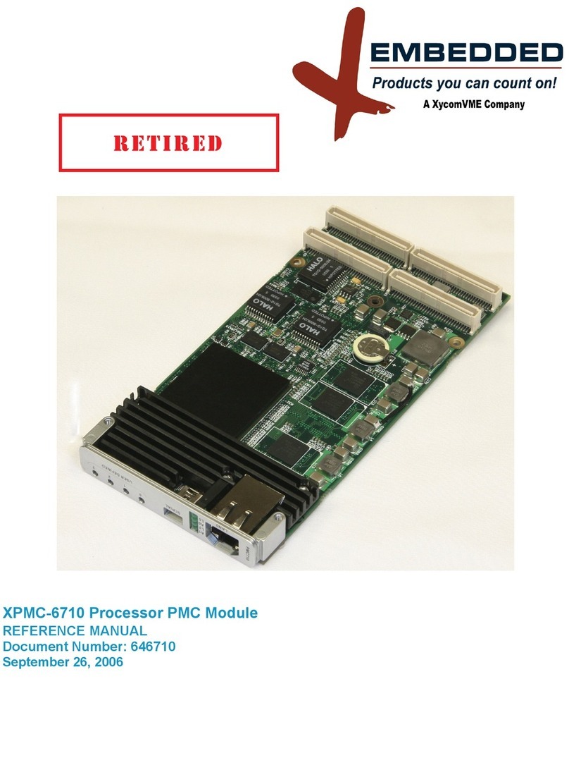
XVME-655
VMEbus Pentium®
Processor Module
P/N 74655-002(H)
ÓÓÓÓ2001XYCOM, INC.
Printed in the United States of America
Artisan Technology Group - Quality Instrumentation ... Guaranteed | (888) 88-SOURCE | www.artisantg.com

Xycom Revision Record
Revision Description Date
A Manual Released 4/96
B Manual Updated 7/96
C Manual Updated with PCN 202 2/97
D Manual Updated 7/97
E Manual Updated 8/97
F Manual Updated 6/98
G Manual Updated 7/00
H Manual Updated 3/01
Trademark Information
Brand or product names are registered trademarks of their respective owners.
Windows is a registered trademark of Microsoft Corp. in the United States and other countries.
Copyright Information
This document is copyrighted by Xycom Incorporated (Xycom) and shall not be reproduced or copied
without expressed written authorization from Xycom.
The information contained within this document is subject to change without notice. Xycom does not
guarantee the accuracy of the information and makes no commitment toward keeping it up to date.
Warning
This is a Class A product. In a domestic environment this product may cause radio interference in which
case the user may be required to take adequate measures.
European Union Directive 89/336/EEC requires that this apparatus comply with relevant ITE EMC
standards. EMC compliance demands that this apparatus is installed within a VME enclosure designed to
contain electromagnetic radiation and that will provide protection for the apparatus with regard to
electromagnetic immunity. This enclosure must be fully shielded. An example of such an enclosure is a
Schroff 7U EMC-RFI VME System chassis that includes a front cover to complete the enclosure.
The connection of nonshielded equipment interface cables to this equipment will invalidate EU EMC
compliance and may result in electromagnetic interference and/or susceptibility levels that violate
regulations that apply to legal operation of this device. It is the responsibility of the system integrator
and/or user to apply the following directions, as well as those in the user manual, that relate to installation
and configuration:
All interface cables should include braid/foil-type shields. Communication cable connectors must be metal
with metal backshells (ideally, zinc die-cast types), and provide 360 degree protection about the interface
wires. The cable shield braid must be terminated directly to the metal connector shell. Shield ground drain
wires alone are not adequate. VME panel mount connectors that provide interface to external cables (e.g.,
RS-232, SCSI, keyboard, mouse, etc.) must have metal housings and provide direct connection to the
metal VME chassis. Connector ground drain wires are not adequate.
Xycom Automation
750 North Maple Road
Saline, MI 48176-1292
734-429-4971
734-429-1010 (fax)
Artisan Technology Group - Quality Instrumentation ... Guaranteed | (888) 88-SOURCE | www.artisantg.com

i
Table of Contents
Chapter 1 – Introduction ................................................................................................................... 1-1
Module Features .............................................................................................................................. 1-1
Architecture...................................................................................................................................... 1-1
CPU Chip ................................................................................................................................. 1-1
PCI Local Bus Interface ........................................................................................................... 1-2
VMEbus Interface .................................................................................................................... 1-2
Expansion Options................................................................................................................... 1-3
On-board Memory.................................................................................................................... 1-3
Serial and Parallel Ports .......................................................................................................... 1-4
Keyboard Interface................................................................................................................... 1-4
Hard and Floppy Drives ........................................................................................................... 1-4
Operational Description.................................................................................................................... 1-5
Environmental Specifications........................................................................................................... 1-6
Hardware Specifications .................................................................................................................. 1-7
Chapter 2 – Installation ..................................................................................................................... 2-1
Voltage Control Module (P4)............................................................................................................ 2-2
Jumper Settings ............................................................................................................................... 2-2
Host Bus Frequency Select ..................................................................................................... 2-2
PCI Bus Frequency Select....................................................................................................... 2-2
CPU Clock Selection................................................................................................................ 2-2
Lattice Programming Port (J5)................................................................................................. 2-3
ORB_GND Selection ............................................................................................................... 2-3
VGA Enable ............................................................................................................................. 2-3
Switch Settings................................................................................................................................. 2-3
Registers.......................................................................................................................................... 2-3
Register 219h – LED/BIOS Port .............................................................................................. 2-4
Register 218h – TEMP/Abort Port ........................................................................................... 2-4
Connectors....................................................................................................................................... 2-5
Serial Port Connectors............................................................................................................. 2-5
Parallel Port Connector............................................................................................................ 2-5
VGA Connector........................................................................................................................ 2-6
Keyboard Port Connector ........................................................................................................ 2-6
VMEbus Connectors ................................................................................................................ 2-7
Interboard Connector 1 (P5) .................................................................................................... 2-9
Interboard Connector 2 (P3) .................................................................................................. 2-10
CPU Fan Power Connector ................................................................................................... 2-11
Installing the XVME-655 into a Backplane..................................................................................... 2-11
Chapter 3 – BIOS Setup Menus........................................................................................................ 3-1
Artisan Technology Group - Quality Instrumentation ... Guaranteed | (888) 88-SOURCE | www.artisantg.com

Table of Contents
ii
Moving through the Menus............................................................................................................... 3-1
BIOS Main Setup Menu ................................................................................................................... 3-2
IDE Adapter 0 Master and Slave Submenus ........................................................................... 3-3
Memory Cache Submenu ........................................................................................................ 3-5
Memory Shadow Submenu...................................................................................................... 3-6
Boot Sequence Submenu ........................................................................................................ 3-7
Numlock Submenu .................................................................................................................. 3-8
Advanced Menu ....................................................................................................................... 3-9
Integrated Peripherals Submenu ........................................................................................... 3-10
Advanced Chipset Control Submenu..................................................................................... 3-11
PCI Devices Submenu........................................................................................................... 3-12
Security Menu ................................................................................................................................ 3-13
VMEbus Setup Menu ..................................................................................................................... 3-15
System Controller Submenu .................................................................................................. 3-16
Master Interface Submenu .................................................................................................... 3-17
Slave Interface Submenus..................................................................................................... 3-18
Interrupt Signals Submenu .................................................................................................... 3-19
Exit Menu ....................................................................................................................................... 3-20
BIOS Compatibility ......................................................................................................................... 3-21
Chapter 4 –Programming................................................................................................................. 4-1
Memory Map .................................................................................................................................... 4-1
I/O Map ............................................................................................................................................ 4-2
IRQ Map........................................................................................................................................... 4-3
VME Interface .................................................................................................................................. 4-4
System Resources................................................................................................................... 4-4
VMEbus Master Interface ........................................................................................................ 4-4
VMEbus Slave Interface .......................................................................................................... 4-5
VMEbus Interrupt Handling...................................................................................................... 4-6
VMEbus Interrupt Generation .................................................................................................. 4-7
VMEbus Reset Options............................................................................................................ 4-7
PCI BIOS Functions......................................................................................................................... 4-7
Calling Conventions ................................................................................................................. 4-8
PCI BIOS Function Calls.......................................................................................................... 4-9
Chapter 5 –XVME-978 PCI Ethernet Controller Module ................................................................ 5-1
Architectural Block Diagram............................................................................................................. 5-1
Installation ........................................................................................................................................ 5-1
Pinouts ............................................................................................................................................. 5-3
Interboard Connector 1 (P6) .................................................................................................... 5-4
Interboard Connector 2 (P4) .................................................................................................... 5-6
Environmental Specifications........................................................................................................... 5-7
Chapter 6 –XVME-973 Drive Adapter Module ................................................................................ 6-1
Installation ........................................................................................................................................ 6-1
Connectors....................................................................................................................................... 6-2
Artisan Technology Group - Quality Instrumentation ... Guaranteed | (888) 88-SOURCE | www.artisantg.com

Table of Contents
iii
P1 Connector ........................................................................................................................... 6-2
P2 Connector ........................................................................................................................... 6-3
P3 Connector ................................................................................................................................... 6-4
P4 Connector ........................................................................................................................... 6-5
P5 Connector ........................................................................................................................... 6-6
Chapter 7 –XVME-978/2 PCI Ethernet/SCSI Controller Module................................................... 7-1
Architectural Block Diagram............................................................................................................. 7-1
Installation ........................................................................................................................................ 7-2
Jumper Settings ............................................................................................................................... 7-3
Loading the Ethernet Driver ............................................................................................................. 7-4
Loading the SCSI Driver .................................................................................................................. 7-4
Enabling the SCSI Boot Capabilities on the XVME-655 .................................................................. 7-4
Pinouts ............................................................................................................................................. 7-4
Interboard Connector 1 (P4) .................................................................................................... 7-5
Interboard Connector 2 (P6) .................................................................................................... 7-6
RJ-45 10/100 Base-T Connector ............................................................................................. 7-7
Environmental Specifications........................................................................................................... 7-8
Appendix A –DRAM Installation ......................................................................................................A-1
Appendix B –External Cache (COAST) Installation..................................................................... B-1
Appendix C –Video Modes ............................................................................................................. C-1
Appendix D –XVME-655 Schematics ............................................................................................. D-1
Appendix E –XVME-973 Schematics...............................................................................................E-1
Appendix F –XVME-978/1 Schematics............................................................................................ F-1
Index ....................................................................................................................................................... i
Artisan Technology Group - Quality Instrumentation ... Guaranteed | (888) 88-SOURCE | www.artisantg.com

1-1
Chapter 1 – Introduction
The XVME-655 Pentium®PC/AT™-compatible VMEbus processor module is designed
to combine the high performance and ruggedized packaging of the VMEbus with the
broad application software base of the IBM PC/AT standard. The module integrates the
latest processor and chipset technology. At the core of the module is an Intel®Pentium
CPU, the highest performance PC-compatible processor available today. This new
generation of Pentium processors uses power-reducing technology, allowing them to run
at higher speeds and temperatures than their predecessors.
Module Features
The XVME-655 offers the following features:
·75, 100, 133, 166, and 200 MHz Pentium CPUs, and 200 and 233 MHz MMX™
Pentium CPUs
·8 Mbyte to 64 Mbyte fast-page EDO DRAM
·512 Kbyte synchronous pipeline Level 2 cache (COAST) on 133, 166, 200, or 233
MHz CPU configurations
·PCI local bus
·PCI local bus SVGA controller, 1024 x 768
·PCI enhanced IDE controller with DMA
·PCI to VMEbus interface
·Two 16550-compatible serial ports
·EPP/ECP-compatible parallel port
·Optional PCI and PC/AT expansion
·Optional PCI Ethernet controller with 10BaseT and 10Base2 interfaces
·One floppy drive with a SA-450 interface
Architecture
This section describes the architecture of the XVME-655 processor module.
CPU Chip
The XVME-655 supports 75 MHz, 100 MHz, 133 MHz, 166 MHz, and 200 MHz
Pentium processors, in addition to 200 MHz and 233 MHz MMX Pentium processors.
The Pentium processor features a supescalar architecture with two pipelined integer units
and a pipelined floating point unit which allows two instructions to be executed per
clock cycle. A dynamic branch prediction unit and separate 8 Kbyte data and instruction
caches further enhance Pentium performance.
Artisan Technology Group - Quality Instrumentation ... Guaranteed | (888) 88-SOURCE | www.artisantg.com

Chapter 1 – Introduction
1-2
PCI Local Bus Interface
The PIIX device provides an accelerated PCI-to-ISA interface that includes a high-
performance enhanced IDE controller, PCI and ISA master/slave interfaces, enhanced
DMA functions, and plug-and-play port for on-board devices. The PIIX also provides
many common I/O functions found in ISA-based PC systems, including a seven-channel
DMA controller, two 82C59 interrupt controllers, an 8254 timer/counter, and control
logic for NMI generation.
Video Controller
The PCI bus video controller features a 64-bit graphics engine, with 24-bit RAMDAC
for true color support. Resolutions up to 1024 x 768 with 256 colors are supported. It
also incorporates the latest Green PC monitor plug-and-play features for power savings.
The video controller also offers hardware-assisted video playback for Indeo™, Cinepak™,
and MPEG-1. Refer to Appendix C for information on Super VGA modes supported.
Fast IDE controller
The enhanced IDE controller supports programmed I/O (PIO) and bus mastering DMA
with transfer rates to 22 Mbytes/second. The controller also contains an 8 x 32-bit buffer
for bus master IDE PCI burst transfers, and will support up to two IDE devices.
Caution
The IDE controller supports enhanced PIO modes, which reduce the
cycle times for 16-bit data transfers to the hard drive. Check with your
drive manual to see if the drive you are using supports these modes. The
higher the PIO mode, the shorter the cycle time. As the IDE cable length
increases, this reduced cycle time can lead to erratic operation. As a
result, it is in your best interest to keep the IDE cable as short as
possible.
The PIO modes are selected in the BIOS setup (refer to Chapter 3). The
Autoconfig will attempt to classify the drive connected if the drive
supports the auto ID command. If you experience problems, change the
PIO to standard.
VMEbus Interface
The XVME-655 uses the PCI local bus to interface to the VMEbus. The VMEbus
interface supports full DMA to/from the VMEbus, integral FIFOs for posted writes,
block mode transfers, and read-modify-write operations. The interface contains four
master and four slave images that can be programmed in a variety of modes to allow the
VMEbus to be mapped into the XVME-655 local memory. This makes it easy to
configure VMEbus resources in protected and real-mode programs.
Artisan Technology Group - Quality Instrumentation ... Guaranteed | (888) 88-SOURCE | www.artisantg.com

Chapter 1 –Introduction
1-3
Expansion Options
The XVME-655 offers PCI, PC/104, and Ethernet expansion options. Ethernet expansion
is available through the XVME-978 Ethernet expansion module. By simply plugging the
XVME-978 directly into the XVME-655 PCI expansion connector, you add 32-bit bus
mastering PCI Ethernet controller capabilities to your VMEbus system.
PC/104 and PCI Mezzanine Card (PMC) expansion is available through the XVME-976
module, which plugs into the XVME-978. The XVME-976 offers PMC and PC/104
sites, allowing easy integration of PC/AT-compatible modules in your VMEbus system.
On-board Memory
DRAM Memory
The XVME-655 has two 72-pin SIMM memory sites, providing up to 64 Mbytes of
DRAM. The memory sites can be populated by standard fast page mode memory or
extended data out memory (EDO). EDO memory is designed to improve DRAM read
performance. Using EDO memory improves the back-to-back burst timing to 2-2-2 from
3-3-3 of standard memory.
Secondary Cache
All CPU configurations except the 75 MHz and 100 MHz models come equipped with
512 Kbyte pipeline burst cache.
Flash BIOS
The XVME-655 board provides a location for a Flash BIOS that is used for system and
video BIOS. The Flash socket supports a 256 Kbyte x 8-bit or 512 Kbyte x 8-bit device.
System BIOS and video BIOS are memory mapped in two locations in the Flash device.
Table Chapter 1 -1 provides the memory map for the 512 Kbyte Flash device.
Table Chapter 1 -1. 512 Kbyte Flash Memory Map
Device Address Device System Address
70000h-7FFFFh System BIOS F0000h-FFFFFh also FFFF0000h-FFFFFFFFh
60000h-6FFFFh System BIOS E0000h-EFFFFh also FFFE0000h-FFFEFFFFh
50000h-5FFFFh Option ROM D0000h-DFFFFh also FFFD0000h-FFFDFFFFh
48000h-4FFFFh Option ROM C8000h-CFFFFh also FFFC8000h-FFFCFFFFh
40000h-47FFFh Video BIOS C0000h-C7FFFh also FFFC0000h-FFFC7FFFh
30000h-3FFFFh System BIOS F0000h-FFFFFh also FFFF0000h-FFFFFFFFh
20000h-2FFFFh System BIOS E0000h-EFFFFh also FFFE0000h-FFFEFFFFh
10000h-1FFFFh Option ROM D0000h-DFFFFh also FFFD0000h-FFFDFFFFh
08000h-0FFFFh Option ROM C8000h-CFFFFh also FFFC8000h-FFFCFFFFh
00000h-07FFFh Video BIOS C0000h-C7FFFh also FFFC0000h-FFFC7FFFh
Artisan Technology Group - Quality Instrumentation ... Guaranteed | (888) 88-SOURCE | www.artisantg.com

Chapter 1 –Introduction
1-4
An on-board switch controls which part of the Flash device is loaded into shadow
DRAM. This allows you to update half the Flash device and still retain a copy of the
original BIOS if the update is not successful or the BIOS is incorrect. To determine
which section of the BIOS is being used, write to port 219h (bit 2=0) and then read bit 3
from port 219h. If bit 3 returns a zero, the lower portion of the BIOS is being used.
Serial and Parallel Ports
PC/AT peripherals include two high-speed 16550-compatible serial ports, one ECP/EPP
parallel port, and a PS/2-compatible keyboard port.
Keyboard Interface
The keyboard interface uses a PS/2-style connector out the front panel. The +5 V is
protected with a polyswitch. This device opens if the +5 V is shorted to GND. Once the
shorting condition is removed, the polyswitch will allow current flow to resume.
Hard and Floppy Drives
The XVME-655’s IDE hard drive and floppy drive signals are routed through the P2
connector, providing a simplified method of connecting external floppy and hard drives.
The XVME-655 supports only one floppy drive.
When used with the XVME-977 mass storage module, hard and floppy drives do not
have to be located next to the processor. The XVME-977 can be installed in any
unoccupied VMEbus slot, and then connected to the XVME-655 through a cable on the
J2 connectors. This allows greater flexibility in configuring a VMEbus card cage.
For applications that require mass storage outside the VMEbus chassis, the XVME-973
driver adapter module plugs onto the VMEbus P2 connector. This module provides
industry standard connections for IDE and floppy signals. You can connect one floppy
drive to the XVME-973. This drive may be 2.88 Mbytes, 1.44 Mbytes, 1.2 Mbytes, 720
Kbytes, or 360 Kbytes.
Caution
The total cable length must not exceed 18 inches. Also, if two drives are
connected, they must be no more than six inches apart.
Artisan Technology Group - Quality Instrumentation ... Guaranteed | (888) 88-SOURCE | www.artisantg.com

Chapter 1 –Introduction
1-5
Operational Description
Figure Chapter 1 -1 illustrates the XVME-655 block diagram.
Figure Chapter 1 -1. XVME-655 Block Diagram
Artisan Technology Group - Quality Instrumentation ... Guaranteed | (888) 88-SOURCE | www.artisantg.com

Chapter 1 –Introduction
1-6
Environmental Specifications
Table Chapter 1 -2. Environmental Specifications
Characteristic Specification
Temperature
Operating
with external 100 CFM fan
forced air flow
200 MHz MMX
233 MHz MMX
Non-operating
0°to 46°C (32°to 114°F)
0°to 43°C (32°to 109°F)
-40°to 85°C (-40°to 185°F)
Vibration
Frequency
Operating
(with COAST module in
stalled)
Non-operating
5 to 2000 Hz
.015" peak-to-peak displacement, 2.5 g
(maximum) acceleration
.015" peak-to-peak displacement, 1 g (maximum)
acceleration
.030" peak-to-peak displacement, 5.0 g
(maximum) acceleration
Shock
Operating
Non-operating
30 g peak acceleration, 11 msec duration
50 g peak acceleration, 11 msec duration
Humidity 20% to 95% RH, non-condensing
Artisan Technology Group - Quality Instrumentation ... Guaranteed | (888) 88-SOURCE | www.artisantg.com

Chapter 1 –Introduction
1-7
Hardware Specifications
Table Chapter 1 -3. Hardware Specifications
Characteristic Specification
Power Specifications
+12V
-12V
+5V
75 MHz
100 MHz
133 MHz
166 MHz
200 MHz
200 MHz MMX
233 MHz MMX
75 mA maximum
24 mA maximum
5.1 A (maximum), 3.9 A (typical)
5.8 A (maximum), 4.6 A (typical)
5.8 A (maximum), 4.5 A (typical)
6.4 A (maximum), 5.0 A (typical)
7.3 A (maximum), 5.8 A (typical)
10.02 A (maximum), 7.42 A (typical)
10.59 A (maximum), 8.19 A (typical)
CPU speed (MHz) 75, 100, 133, 166, 200, 200 MMX, or 233
MMX
PCI Super VGA Graphics
Controller
1024x768, 256 colors maximum resolution
1 Mbyte video DRAM
Serial Ports (2) 16550 compatible
Parallel Interface EPP/ECP compatible
On-board memory EDO DRAM, 8 to 64 Mbytes
VMEbus Compliance
Complies with VMEbus Specification, IEEE 1014–1987 Rev. C.1
A32/A24/A16:D64/D32/D16/D08(EO) DTB Master
A32/A24:D64/D32/D16/D08(EO) DTB Slave
R(0-3) Bus Requester
Interrupter I(1)-I(7) DYN
IH(1)-IH(7) Interrupt Handler
SYSCLK and SYSRESET Driver
PRI, SGL, RRS Arbiter
RWD, ROR bus release
Form Factor: Double-height, double-width 233.35 mm x 160 mm (9.2”x 6.3”)
Artisan Technology Group - Quality Instrumentation ... Guaranteed | (888) 88-SOURCE | www.artisantg.com
2-1
Chapter 2 –Installation
This chapter provides information on configuring the XVME-655. It also provides
information on installing the module into a backplane.
Figure Chapter 2 -1 illustrates the jumper, switch, and connector locations on the
XVME-655.
Figure Chapter 2 -1. XVME-655 Jumper, Switch, and Connector Locations
Artisan Technology Group - Quality Instrumentation ... Guaranteed | (888) 88-SOURCE | www.artisantg.com
Chapter 2 –Installation
2-2
Voltage Control Module (P4)
Because MMX CPU chips have different voltage requirements than non-MMX CPU
chips, MMX CPUs require special voltage control modules.
CPU Type Voltage Control Module Part Number
MMX 122032A-001
Non-MMX 108168A-001
Warning
If you use the non-MMX voltage control module (part number 108168A-
001) with MMX CPUs, you may damage the CPU chip.
Jumper Settings
Table Chapter 2 -1 defines the default jumper settings for the XVME-655’s processor
configurations.
Table Chapter 2 -1. Default Jumper Settings
Configuration J1J2J3J4J6J7J8
75MHz ABBBAAB
100 MHz A A A B A A B
133 MHz A A A B B A B
166 MHz A A A B B B B
200/200 MMX MHz A A A B A B B
233 MMX MHz A A A B A A B
Host Bus Frequency Select
J7 (BF1) J6 (BF) Frequency Fraction
B B 2/5 (150/166)
B A 1/3 (200/200 MMX)
A B 1/2 (120/133)
A A 2/3 (75/90/100)
A A 1/3.5 (233 MMX)
PCI Bus Frequency Select
J2 PCI Frequency to set up AT-bus
A 33 MHz/30 MHz
B 25 MHz
CPU Clock Selection
J4 J3 Frequency Fraction
Artisan Technology Group - Quality Instrumentation ... Guaranteed | (888) 88-SOURCE | www.artisantg.com
Chapter 2 –Installation
2-3
B B 50 MHz (75)
A B 60 MHz (90/120/150)
B A 66 MHz
(100/133/166/200/
200 MMX/233 MMX)
A A Undefined
Lattice Programming Port (J5)
This jumper is reserved for Xycom use.
ORB_GND Selection
J8 ORB_GND Connected to Digital GND
ANo
BYes
VGA Enable
J1 VGA Enable
A Enable
B Disable
Switch Settings
The XVME-655 has one eight-position switch, as described in Table Chapter 2 -2. (Ö
indicates the default setting.)
Table Chapter 2 -2. Switch Settings
Position Open Closed
1 VME resets only VME interface ÖVME reset causes CPU and VME interface reset
2 Front panel toggle switch
causes no VMEbus reset
ÖFront panel toggle switch causes VMEbus reset
3ÖSysfail asserted on VME
reset
Sysfail not asserted on VME reset
4ÖCMOS okay CMOS cleared by BIOS
5 Front panel toggle switch
causes no CPU reset
ÖFront panel toggle switch causes CPU reset
6ÖUpper Flash BIOS Lower Flash BIOS
7ÖKeyboard as input Keyboard inhibit
8ÖColor Monochrome
Registers
The XVME-655 contains two I/O ports: 219h and 218h.
Artisan Technology Group - Quality Instrumentation ... Guaranteed | (888) 88-SOURCE | www.artisantg.com
Chapter 2 –Installation
2-4
Register 219h – LED/BIOS Port
Table Chapter 2 -3 describes the LEDs and signals that register 219 controls.
Table Chapter 2 -3. LED/BIOS Port
Bit LED/Signal Result R/W
0 FAULT 1 = Fault LED off
0 = Fault LED on
R/W
1 PASS 1 = PASS LED on
0 = PASS LED off
R/W
2 FLASHWR 1 = Flash write enabled/A18 enable R/W
3 FLB-A18 Flash BIOS Address A18; when FLASHWR = 0
reads switch position 6
R
4 Reserved 0 R/W
5 BIOS_C8 1 = Enable C8000h-CFFFFh on-board BIOS R/W
6 BIOS_D0 1 = Enable D0000h - D7FFFh on-board BIOS R/W
7 BIOS_D8 1 = Enable D8000h - DFFFFh on-board BIOS R/W
Register 218h – TEMP/Abort Port
This register controls the temperature sensor and the abort toggle switch. It also allows
you to read the CMOS clear switch and VGA enable.
Table Chapter 2 -4. Temp/Abort Port
Bit Signal Result R/W
0 TS_RESET 0 = Reset temperature sensor interface R/W
1 TS_WRITE Write data bit must be high when reading
temperature sensor
R/W
2 TS_DQ Temperature sensor read data bit R
3 TS_CLK A low to high will clock in or clock out bit R/W
4 ABORT_STS 1 = Abort toggle switch caused interrupt R
5 ABORT_CLR 1 = Enable abort
0 = Clear and disable abort
R/W
6 VGA_EN 1 = On-board VGA controller enabled R
7 CLRCMOS 1 = CMOS okay
0 = Clear CMOS
R
Artisan Technology Group - Quality Instrumentation ... Guaranteed | (888) 88-SOURCE | www.artisantg.com

Chapter 2 –Installation
2-5
Connectors
This section provides the pinouts for the XVME-655 connectors.
Serial Port Connectors
COM1 COM2
Pin Signal Pin Signal
1 DCD1 1 DCD2
2 RXD1 2 RXD2
3TXD1 3TXD2
4 DTR1 4 DTR2
5GND 5GND
6 DSR1 6 DSR2
7RTS1 7RTS2
8CTS1 8CTS2
9RI1 9RI2
Parallel Port Connector
Pin Signal Pin Signal
1 STROBE 14 AUTOFEED
2 PDOUT0 15 PERROR
3 PDOUT1 16 INIT
4 PDOUT2 17 SELIN
5 PDOUT3 18 GND
6 PDOUT4 19 GND
7 PDOUT5 20 GND
8 PDOUT6 21 GND
9 PDOUT7 22 GND
10 PACK 23 GND
11 PBUSY 24 GND
12 PE 25 GND
13 SELECT
Artisan Technology Group - Quality Instrumentation ... Guaranteed | (888) 88-SOURCE | www.artisantg.com

Chapter 2 –Installation
2-6
VGA Connector
Pin Signal
1RED
2 GREEN
3 BLUE
4NC
5GND
6GND
7GND
8GND
9 KEY
10 GND
11 NC
12 DDC.ID
13 HYSNC
14 VSYNC
15 NC
Keyboard Port Connector
Pin Signal
1DATA
2NC
3GND
4+5V
5CLK
6NC
Artisan Technology Group - Quality Instrumentation ... Guaranteed | (888) 88-SOURCE | www.artisantg.com

Chapter 2 –Installation
2-7
VMEbus Connectors
P1 and P2 are the VMEbus connectors.
P1 Connector
Pin A B C
1 D00 BBBUSY D08
2 D01 BCLR* D09
3 D02 ACFAIL* D10
4 D03 BG0IN* D11
5 D04 BG0OUT* D12
6 D05 BG1IN* D13
7 D06 BG1OUT* D14
8 D07 BG2IN* D15
9 GND BG2OUT* GND
10 SYSCLK BG3IN* SYSFAIL*
11 GND BG3OUT BERR*
12 DS1* BR0* SYSRESET
13 DS0* BR1* LWORD*
14 WRITE* BR2* AM5
15 GND BR3* A23
16 DTACK* AM0 A22
17 GND AM1 A21
18 AS* AM2 A20
19 GND AM3 A19
20 IACK* GND A18
21 IACKIN* NC A17
22 IACKOUT* NC A16
23 AM4 GND A15
24 A07 IRQ7* A14
25 A06 IRQ6* A13
26 A05 IRQ5* A12
27 A04 IRQ4* A11
28 A03 IRQ3* A10
29 A02 IRQ2* A09
30 A01 IRQ1* A08
31 -12V NC +12V
32 +5V +5V +5V
Artisan Technology Group - Quality Instrumentation ... Guaranteed | (888) 88-SOURCE | www.artisantg.com
Table of contents
Other Xycom Computer Hardware manuals
Popular Computer Hardware manuals by other brands

ICP
ICP GDT8500RZ Installation and user guide

Adeunis RF
Adeunis RF ARF8020AA user guide

PerfecTron
PerfecTron OXY5362A user manual

Keysight Technologies
Keysight Technologies N5221BU-4S7 manual

LOVATO ELECTRIC
LOVATO ELECTRIC EXP10 12 instruction manual

ZyXEL Communications
ZyXEL Communications MAX-506 - V1.00 datasheet