manuals.online logo
Brands
  1. Home
  2. •
  3. Brands
  4. •
  5. Xylem
  6. •
  7. Water Pump
  8. •
  9. Xylem LOWARA Hydroquench 3000 MK2 Manual

Xylem LOWARA Hydroquench 3000 MK2 Manual

Operating and Maintenance Instructions
EC Declaration of conformity
Xylem Water Solutions UK Limited declare that the Hydroquench 3000 sprinkler pump set conforms to the
requirements of the Machinery Safety Directive 2006/42/EC
Electromagnetic compatibility (EMC) Directive 2014/30/EU
Conforming to the UK Health & Safety Requirements 2008 No. 1597
Signed: Position: Engineering manager Date: 20-04-2016 Revision B
Clive Willmott
Introduction
This leaflet contains information to enable the safe installation and operation of the products mentioned above.
The following instructions must be read and understood by all persons responsible for the installation, operation
and maintenance of this product.
Warning Symbols
Safety instructions where noncompliance would affect safety.
Safety instruction where electrical hazard is involved.
Safety instruction where noncompliance could cause damage to the equipment.
Instruction for safe us
This product has been designed for collecting and boosting rain water in non potable water
installations to the operating conditions shown.
This product should not be installed until this leaflet has been studied carefully.
Handling, transportation and installation of this equipment should only take place with the proper
use of lifting equipment.
This product must be stored in a frost-free dry environment.
Noise Emission
This equipment operates at a noise level lower than 70dBA.
Protection degree Motor and control panel IP55.
Hydroquench 3000 MK2
Domestic/Residential Sprinkler Pump Set
British Standard 9251
1
Installation
The Hydroquench 3000 unit is despatched mounted on a wooden pallet and covered in a protective film, it is
recommended that the unit be retained in the protective packaging until the product is to be in-
stalled. The unit will arrive pre-packaged and wired ready for installation.
This product has been fully run tested at our works under simulated site conditions.
The unit should be sited in a dry clean well-ventilated area with good all round access.
Electrical connections
The cable used for the incoming supply must be of adequate size to carry the motor full load
current. This is shown on the duty plate. All non power caballing should be limited to 2.5mm.
All connections must be made using the appropriate wiring drawings for the equipment being
installed, with particular attention being paid to the supply voltages.
The supply voltage is shown on the set duty plate.
Never operate this product with the control panel lid removed
It is essential that this equipment is earthed to the building earth system
The base frame must be earth bonded directly to the building earth system.
All wiring should be arranged such that it enters the control panel through the appropriate cable
glands.
Water supply/storage
The sprinkler set should be connected to a water storage tank of adequate size and provide the
pump with positive suction head, these sets are NOT suitable for suction lift applications.
For domestic installations the storage tank should have a minimum capacity of 1200 litres, if the
same tank is used for domestic purposes then a minimum capacity of 1320Litres should be
used. The domestic supply pipe should be positioned in the storage tank above the storage
capacity for the sprinkler system.
For residential installations the storage tank should have a minimum capacity of 7200 Litres. Under certain
circumstances the sprinkler set may be connected directly to main incoming water supply providing the local
water authority have approved the installation. Each installation will need to be submitted to the local water
authority for approval. If the installation is approved for direct connection by the water authority then appropri-
ate back flow prevention devices and recirculation solenoid valve must be fitted.
Recirculation connections
A small bore recirculation pipe should be connected between the set and the storage tank. The valve should
have been factory set to 1 L/m at closed valve head. If the valve has been tampered with then the flow rate
should be rechecked.
Note: If the break tank is used for the domestic water supply as well as feeding the fire set then alternative
arrangements must be made for the recirculation line to pass water to drain via an anti-siphon air gap and not
go back to the break tank.
Again if the unit is fed directly from a mains water supply then consideration must be given to fitting a solenoid
valve to the recirculation line so water will be discharged to drain when the pump set starts.
Suction and discharge connections
Isolation ball valves are fitted to both suction and discharge lines, connection sizes vary with
pump size.
See Installation drawing for connection details.
All pipe work connected to the set must be self supporting.
2
Integral vessel
The sprinkler set contains an 8 Lt vessel which is pre-charged with Nitrogen (dry air) the vessel
should be pre-charged to 0.5 Bar below the system pressure. To check the Pre-charge value,
the vessel must be isolated from the system. To check vessel, turn both suction and discharge
ball valves to the closed position, isolate power to control panel.
Note this will cause the general alarm contact to operate and if connected may signal back to main control
panel that power has been lost. Remove system pressure by draining water from set via the drain valve
adjacent to the vessel. The vessel pre-charge can now be checked using an appropriate pressure gauge.
Re-charge as necessary with Nitrogen.
Commissioning
The following procedure is based on the set being configured as standard I.E, Manual
stop, other configurations will be covered further on in this manual.
Ensure the storage tank feeding the sprinkler pump set is full and has a healthy mains water
supply.
Open the suction line ball valve and allow water to enter the set, open the bleed screw on the pump housing
and allow all air to escape, when water is flowing freely close bleed screw. Open drain cock adjacent to
vessel and allow all air to escape, when water is flowing freely, close drain cock. Open discharge valve to
system.
Switch power supply to sprinkler set control panel to the on position and the pump set will start and fill the
system to the set point. Once the system pressure has been reached and flow has cessed the on demand
LED will be extinguished and the stop button can be operated to stop the pump. Because the pump set
continues to run until manually stopped the system pressure will more often than not reach the closed valve
head of the pump.
Note; after initial power up the internal audible alarm for the first 10 minutes will operate at a reduced volume
after this time period it will revert to normal volume.
If the pump set starts due to an alarm condition, the internal audible alarm will sound continually whilst the
pump is running.
Pressure switch setting
Both pressure switches have been factory set and should not need further adjustment, however
if settings need to be changed then proceed as follows.
PSI monitors the system pressure and PS2 monitors the pump test pressure.
The differential on PS1 should be set to approximately 1 bar depending on pump type.
The approximate pressure set point can be read from the pressure switch range window, turn adjusting knob
clockwise to increase and anti-clockwise to decrease set point.
The test pressure switch has a fixed differential and should be set to approximately 1 Bar below the system
set point.
Flow switch
The flow switch has been factory set and should not be adjusted under any circumstances.
Operation with Standard configuration (Manual stop)
At rest the system will be pressurised to the duty set point (this may be the closed valve head of
pump).
If the temperature rises at any of the sprinkler heads to a pre-determined level then the glass
bulb in that head will rupture and activate that sprinkler head.
This will cause flow to take place and the pressure in the system to fall; the fire set will respond to this flow
and drop in pressure and start a pump to maintain flow.
3
4
The set will now continuously run, when pressure has been raised to the duty point and the flow switch has
registered no flow is taking place, the on demand indicator will be extinguished and the pump set can be
stopped by pressing the stop button on the control panel.
If the set point has not been satisfied or flow is taking place then the on demand indicator will be illuminated
and the stop button will have no effect and the pump will continue to run.
To stop the pump set after use, close the discharge valve and the pressure will rise and flow will cease, press
the stop button and the set will stop. Replace the ruptured sprinkler head/s and open the set discharge valve
to bring the set back into operation.
In the advent of water failure where the pump will not be able to make pressure the main power supply should
be isolated until the water supply has been reinstated.
General alarm contact
When the pump set starts, or a fault occurs the internal audible alarm will sound at the set, a failsafe alarm
volt free contact will close to indicate to a remote monitoring device (not supplied) that the pump set has
started or a problem has occurred. This contact will also operate under power failed conditions.
Flow alarm contact
When the pump set starts and flow takes place (indicating a real usage is taking place) the internal audible
alarm will sound at the set and a volt free contact will close, this contact can be used to activate the evacua-
tion alarm circuit (Not supplied).
Pump protection
The pump is protected against short circuit only I.E. fused supply. In the advent of overload the pump will
continue to run until destruction.
Indication
The control panel fascia is fitted with LED indicators for Power on (Green), Pump set on demand (Red) and
pump test failed (red).
Pump test automatic and manual
The pump test time can be set for either 4,7,14,21 or 28 day intervals. The pump will be started and run for
approximately 5 seconds, a pressure switch mounted directly on the pump discharge manifold before the non
return valve will monitor the pump to ensure that the pump has developed pressure within the allotted time.
This will also replenish any loses from the vessel. The volt free alarm contacts and internal alarm sounder will
not operate under successful test operation.
Pump test failure
If the pump fails to make pressure during the test operation then the general alarm volt free contact will oper-
ate, the internal audible alarm will sound and the test failed LED will be illuminated to signal pump failure. The
power supply should be isolated and the fault should be investigated and rectified, the alarm condition will be
reset when the power supply is reinstated.
The above test can be carried out manually at any time by pressing the test button.
Automatic re-pressurisation mode
When this option is selected the pump set will automatically start when pressure falls, and providing flow is
not taking place will re-pressurise the system and automatically stop. The general alarm contact will operate
to show that the set has started and reset when the set stops. The audible alarm will not operate under this
condition.
This option is useful when small losses due to pipe work leakage are difficult to find/repair.
Auto stop 30
When this option is selected the pump set will run on for 30 minutes after demand has been satisfied I.E.
pressure has risen above the cut out point and no flow is taking place. Once 30 minutes has elapsed the
pump set will stop and revert to standby mode. During this run on mode the (on demand) LED will flash fast
to show that the stop time is counting down. Once the time has elapsed and the set has stopped the (on
demand) LED will have a slow flash to show that the set had previously been running, to reset the flashing
LED press the stop button.
Auto stop
When this option is selected the pump set will automatically stop after demand has been satisfied I.E.
pressure has risen above the cut out point and no flow is taking place. The set will reset all alarms and
revert to standby mode.
Pump set Maintenance
The pump set will self test for pressure and pump operation at pre-set intervals as described above, this will
help prevent pump seizure due to inactivity and ensure the pump remains free to rotate.
At 6-monthly intervals:-
1. Check the gas fill pressure in the membrane vessel. This can be effected by following the
procedure set out in integral vessel section above.
2. Check pump mechanical seal is not leaking.
3. Check the break tank is clean and filled to the correct level.
4. Check the electrical system to ensure that all earth wires are intact and securely con
nected. Check and ensure all control panels terminals are tight and making good connection.
5. Check flow and pressure switch operation by connecting a hose pipe to the drain cock situated on the
discharge ball valve. Open valve and allow water to flow to waste the pump should now start and the on
demand indicator should be illuminated. Close drain valve and water flow will now cease and the on demand
indicator will be extinguished. Whilst the pump is running check for any signs of vibration. The stop button can
now be operated and the pump will stop.
Note: Whilst carrying out the above procedure the internal and external alarm will sound, check to ensure
these can be heard in all parts of the building.
5
Fault Possible Cause Remedy
Pump fails to start
Power supply failure
Control panel fuse blown,
pressure switch incorrectly
adjusted
Check main incoming power supply
Check power supply fuse in control panel
Adjust pressure to required set point
Pump fails to stop
(On demand LED off) Manual stop mode selected Press stop button
Pump fails to stop
(On demand LED on)
flow is taking place
pressure switch incorrectly
adjusted
Close discharge valve and press stop
button, if pump stops check for system
leaks.
Adjust pressure to required set point
Pump runs but will not make
pressure
Lack of water
Pump air locked
Isolation valve closed
Incorrect rotation 3PH
Re-circulation line is passing too
much water
Check break tank has adequate supply of
water
Open pump bleed screw and vent pump
Check all isolating valves are open
Reverse two phases
Adjust flow to 1 l/m
Pump overheating Recirculation line not connected
or closed
Connect recirculation line as described in
this manual and ensure valve is open to
pass water
Pump set frequently starting
with no apparent demand
(pressure falls to cut in point)
Newly installed system with large
amount of air in pipe work
Leaks in system pipe work
Vessel pre-charge incorrect
Bleed system to remove air
Repair leaks
Isolate vessel and pre-charge with
Nitrogen as appropriate
Pump will not run
(Pump failed LED on)
Pump test failed due to pump
seizure
Free pump and check the motor rotes
freely
Switch power supply off and then to reset
Internal audible alarm not
working
Audible alarm designed to be
quite for first 10 minutes after
power up
Wait for power to be applied to the set for
more than 10 minutes and check againt
Pump stops and pressure
drops immediately Non-return valve letting by Replace non-return valve
6
General fault finding guide
Xylem Water Solutions UK Limited
Millwey Rise Industrial Estate, Axminster, Devon EX13 5HU - UK
Tel: 01297 630230 Fax: 01297 630270
e-mail: [email protected]
www.lowara.co.uk www.xyleminc.com
Lowara is a trademark of Xylem Inc. or one of its subsidiaries. © 2016 Xylem, Inc.
Lowara reserve the right to make modifications without prior notice.
Code. UKLIT0087 P04/16
7
8
Xylem Water Solutions UK Limited
Millwey Rise Industrial Estate, Axminster, Devon EX13 5HU - UK
Tel: 01297 630230 Fax: 01297 630270
e-mail: [email protected]
www.lowara.co.uk www.xyleminc.com
Lowara is a trademark of Xylem Inc. or one of its subsidiaries. © 2016 Xylem, Inc.
Lowara reserve the right to make modifications without prior notice.
Code. UKLIT0087 P04/16
Hydroquench 3000MK 2 Sprinkler Test Data Sheet
PUMP DATA
Pump size....................................................................................
Pump serial number...................................................................
Motor serial number..................................................................
Motor power...............................................................................
Electrical supply.........................................................................
Motor speed...............................................................................
Date..............................................................................................
TEST
Alarm and panel stop switch test
Flow switch test
Main pressure switch test
Test button test.
Volt free contact test
DATA/LABELS
O and M included
Panel diagram included
Vessel pressure labels attached
Hydroquench label attached
Lot number labels attached
Lowara pumps representative
Signed..........................................................................................
Print Name...................................................................................

Other Xylem Water Pump manuals

Xylem Jabsco 18620-0003 User manual

Xylem

Xylem Jabsco 18620-0003 User manual

Xylem Lowara Scuba Manual

Xylem

Xylem Lowara Scuba Manual

Xylem FLYGT Flygt 2071 User manual

Xylem

Xylem FLYGT Flygt 2071 User manual

Xylem JABSCO 11860 Series User manual

Xylem

Xylem JABSCO 11860 Series User manual

Xylem GOULDS e-SVI Series User manual

Xylem

Xylem GOULDS e-SVI Series User manual

Xylem LOWARA Micro 10 Instruction Manual

Xylem

Xylem LOWARA Micro 10 Instruction Manual

Xylem Bell & Gossett VSC Series User manual

Xylem

Xylem Bell & Gossett VSC Series User manual

Xylem rule RLP900D User manual

Xylem

Xylem rule RLP900D User manual

Xylem Flojet 18555000 User manual

Xylem

Xylem Flojet 18555000 User manual

Xylem FLOJET 2840 Series Operating and installation instructions

Xylem

Xylem FLOJET 2840 Series Operating and installation instructions

Xylem Flygt 2830.180 User manual

Xylem

Xylem Flygt 2830.180 User manual

Xylem FLYGT Compit 901 Series User manual

Xylem

Xylem FLYGT Compit 901 Series User manual

Xylem Flygt 3085 Maintenance manual

Xylem

Xylem Flygt 3085 Maintenance manual

Xylem Bell & Gossett e-1510 Series User manual

Xylem

Xylem Bell & Gossett e-1510 Series User manual

Xylem Goulds MCC Manual

Xylem

Xylem Goulds MCC Manual

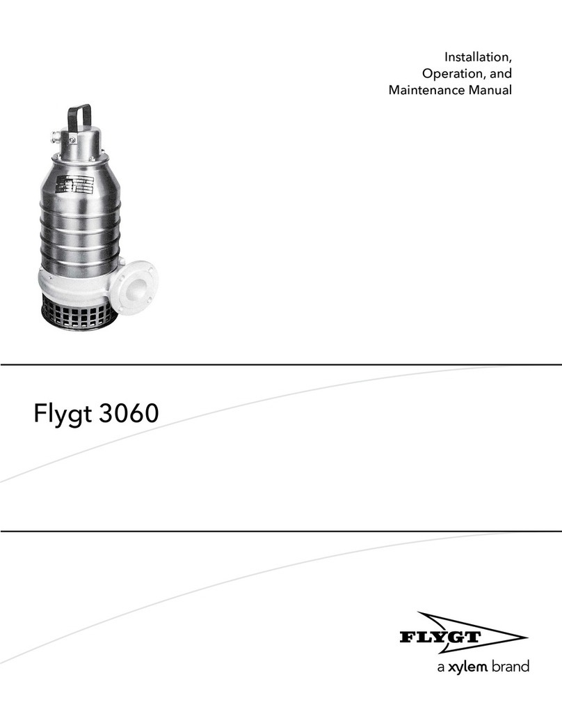
Xylem Flygt 3060 User manual

Xylem

Xylem Flygt 3060 User manual

Xylem GSP0311 User manual

Xylem

Xylem GSP0311 User manual

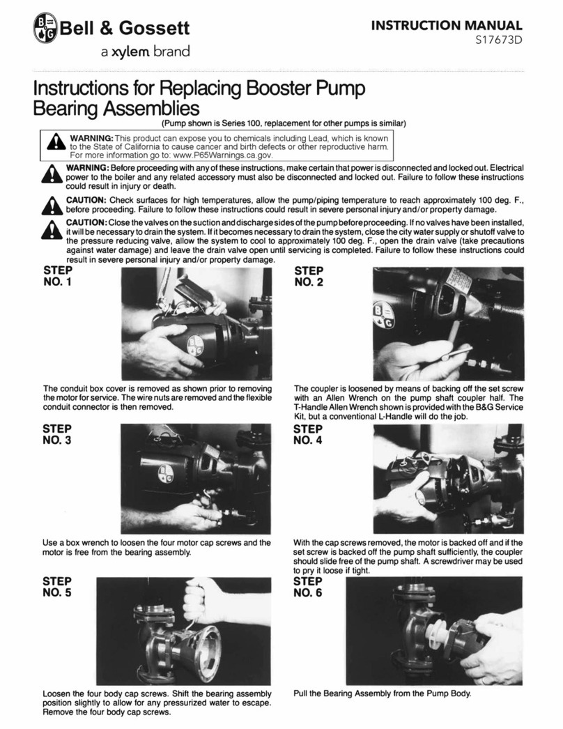
Xylem Bell&Gosset 100 Series User manual

Xylem

Xylem Bell&Gosset 100 Series User manual

Xylem Goulds MPVN Series User manual

Xylem

Xylem Goulds MPVN Series User manual

Xylem Bell & Gossett e-1510 Series User manual

Xylem

Xylem Bell & Gossett e-1510 Series User manual

Xylem LOWARA e-SV Series User manual

Xylem

Xylem LOWARA e-SV Series User manual

Xylem Goulds SHV Series Manual

Xylem

Xylem Goulds SHV Series Manual

Xylem FloJet 3426 Series User manual

Xylem

Xylem FloJet 3426 Series User manual

Xylem GOULDS LC Manual

Xylem

Xylem GOULDS LC Manual

Popular Water Pump manuals by other brands

EasyPro EPS650 Instructions for Operation, Safety, Warranty

EasyPro

EasyPro EPS650 Instructions for Operation, Safety, Warranty

IBO SANIBO 4 instructions

IBO

IBO SANIBO 4 instructions

Flowserve M Series User instructions

Flowserve

Flowserve M Series User instructions

SFA SANISUB 400 Operating & installation manual

SFA

SFA SANISUB 400 Operating & installation manual

Grundfos CM series Service instructions

Grundfos

Grundfos CM series Service instructions

Blue-White industries flexflo A-100N operating manual

Blue-White industries

Blue-White industries flexflo A-100N operating manual

Johnson Pumps SPX FLOW Pro L1600 Series installation instructions

Johnson Pumps

Johnson Pumps SPX FLOW Pro L1600 Series installation instructions

Bestway Built-in Sidewinder P3150 owner's manual

Bestway

Bestway Built-in Sidewinder P3150 owner's manual

Reefe RSWE40 Exploded View & Instruction Manual

Reefe

Reefe RSWE40 Exploded View & Instruction Manual

Oase Bitron C operating instructions

Oase

Oase Bitron C operating instructions

BARTON TOOLS HHB-150B instruction manual

BARTON TOOLS

BARTON TOOLS HHB-150B instruction manual

Bell and Gossett Series 1510 instruction manual

Bell and Gossett

Bell and Gossett Series 1510 instruction manual

Giant LP122A-3100 Operating instructions/ repair and service manual

Giant

Giant LP122A-3100 Operating instructions/ repair and service manual

Pentair HYPRO 9343 Series Original instruction manual

Pentair

Pentair HYPRO 9343 Series Original instruction manual

GORMAN-RUPP PUMPS T6B3S-B Installation, operation, and maintenance manual with parts list

GORMAN-RUPP PUMPS

GORMAN-RUPP PUMPS T6B3S-B Installation, operation, and maintenance manual with parts list

Leybold vacuum TRIVAC S 4 B operating instructions

Leybold vacuum

Leybold vacuum TRIVAC S 4 B operating instructions

OSIP VC 50 instructions

OSIP

OSIP VC 50 instructions

EINHELL Royal TMP 550-iS operating instructions

EINHELL

EINHELL Royal TMP 550-iS operating instructions

manuals.online logo
manuals.online logoBrands
  • About & Mission
  • Contact us
  • Privacy Policy
  • Terms and Conditions

Copyright 2025 Manuals.Online. All Rights Reserved.