XYZ Machine Tools TRAK 2OP M11 Mill Guide

XYZ Machine Tools Ltd.
Woodlands Business Park
Burlescombe, Tiverton, Devon EX16 7LL
T: 01823 674200 F: 01823 674201
e-mail: sales@xyzmachinetools.com
www.xyzmachinetools.com
XYZ
TRAKTM 2OP M11 Mill
Safety, Installation, Maintenance, Service and Parts List
Document: P/N 28170-1
Version: 050919

Copyright © 2019 XYZ Machine Tools, Ltd. All rights are reserved. No part of this publication may be
reproduced, stored in a retrieval system, or transmitted, in any form or by any means, mechanical,
photocopying, recording or otherwise, without the prior written permission of XYZ Machine Tools, Ltd.
While every effort has been made to include all the information required for the purposes of this guide, XYZ
Machine Tools assumes no responsibility for inaccuracies or omission and accepts no liability for damages
resulting from the use of the information contained in this guide.
All brand names and products are trademarks or registered trademarks of their respective holders.
XYZ Machine Tools
Woodlands Business Park
Burlescombe, Nr Tiverton
Devon, EX16 7LL
Service Department
Tel: 01823 674214
Fax: 01823 674201

i
XYZ Machine Tools Ltd
TRAK2
OP
Installation, Maintenance, Service & Part List Manual
Table of Contents
1.0 Safety 1
1.1 Safety Publications
1.2 Danger, Warning, Caution and Note Labels and
Notices Used in this Manual
1.3 Safety Precautions
2.0 System Description 11
2.1 Machine Specifications
2.2 Maximum Spindle Torque & HP
2.3 ProtoTRAK TMX Control Hardware
2.4 Machine Major Subassemblies
3.0 Installation 19
3.1 Lifting the 2 OP mill
3.2 Uncrating the 2 OP
3.3 Shortages: Inventory Checklist
3.4 Installation Checklist
3.5 Electrical Connections
3.6 Air Connections
3.7 Cleaning the 2 OP
3.8 Leveling Procedure
3.9 Lubrication
3.10 Moving the 2 OP Around the Shop
3.11 Cutting the Euclid Test Block
4.0 Troubleshooting by Symptom 27
4.1 Machine Related Problems
4.2 Motion Related Problems
4.3 Control Related Problems
4.4 Tool Changer (Carrier) Problems
4.5 Control Input or Output Problem
4.6 Measurement Problems
4.7 Machine Tool Problems
5.0 Diagnostics 43
5.1 The Machine Tool & Setup
5.2 The Mechanical Drive Train
5.3 Computer Module
5.4 Programming Panel
5.5 Axis Motors/Servos
5.6 Spindle Motor & Inverter
5.7 Electrical
5.8 Tool Carrier Diagnostics
5.9 Pneumatic Diagnostics
5.10 Coolant System Diagnostics
5.11 Service Codes
6.0 Replacement Procedures 90
6.1 Axis Motor Replacement
6.2 AC Spindle Drive Replacement
6.3 Computer Module Replacement
6.4 Linear Guide Replacement
6.5 Ballscrew Replacement – X Axis
6.6 Ballscrew Replacement – Y Axis
6.7 Ballscrew Replacement – Z Axis
6.8 Spindle Motor Replacement
6.9 Spindle Motor Wiring
6.10 Spindle Cartridge Replacement
6.11 Spindle/Motor Coupling Alignment
6.12 Automatic Tool Carrier (ATC) Replacement
6.13 Setting ATC Locations
6.14 Coolant Pump Replacement
6.15 Bleeding Air from Tool Unclamp Cylinder Oil System
6.16 Programming Panel Replacement
6.17 Home Switch Replacement
6.18 Spindle Motor Encoder Replacement
6.19 X, Y & Z Home Switch Adjustments
6.20 Adjusting the Drawbar Bump Out
6.21 Servo Drive Replacement
6.22 Setting Spindle Orientation – Service code 510
7.0 Maintenance 115
7.1 Calibration
7.2 Backlash Compensation
7.3 Periodic Maintenance

ii
XYZ Machine Tools Ltd
TRAK2
OP
Installation, Maintenance, Service & Part List Manual
8.0 Assembly Drawings 116
Machine Assembly – 27600-5
System Diagram – 27648-5
Enclosure Assembly – 27568-2
Base Frame Assembly – 27542-2
X Axis Drive Train – 27520-1
Y Axis Drive Train – 27564-2
Z Axis Drive Train – 27540-1
Programming Panel Assembly – 28160
ATC Assembly – 27587-1
Spindle Head Assembly – 27500-1
Spindle Cartridge Assembly – 27830-1
Pneumatic System – 27563-2
Coolant System – 27557
Lubrication System – 27591-1
Home Switch Assembly – 27658-1
Electrical Cabinet Assembly – 27621-5
Electrical Schematic – 27650-5-SCH
Enclosure Assembly – Servo Drives – 28156-1

1
XYZ Machine Tools Ltd
TRAK2
OP
Installation, Maintenance, Service & Part List Manual
1Safety
The safe operation of the 2 OP Mill depends on its proper use and the precautions taken by each operator.
1.1 Safe Operating Information
It is the responsibility of the employer, machine owner or machine controller to ensure that this machine is
installed, operated and maintained in accordance with the Provision and Use of Work Equipment
Regulations 1998 (PUWER) or equivalent local regulations.
In particular, the responsible person must:
•Undertake a Risk Assessment on the use of this machine, paying particular attention to the specific
characteristics of this machine; including:
oTransportation by trolley jack,
oUnrestricted operating mode selection.
•Generate and apply Safe Operating Procedures for the use of the Prototrak machine
•Provide any additional training, safeguarding or PPE identified by the risk assessment.
For more information, see the HSE Guidance document INDG291 “Providing and using work equipment
safely” available from the HSE website (http://www.hse.gov.uk/pubns/)
This machine, as supplied, is intended to be used for material removal by conventional milling processes on
common engineering materials, in manual or CNC controlled modes.
A risk assessment must always be undertaken to identify any special hazards due to specific processes or
materials and additional safety measures applied as appropriate. Special cases to consider include, but are
not limited to:
•Potentially flammable materials (e.g. magnesium, aluminium, titanium), or
•Materials which generate hazardous dusts when machined (e.g. Tufnol, beryllium).
This machine is designed to be used in a standard workshop environment only. It must not be used in
potentially explosive atmospheres.
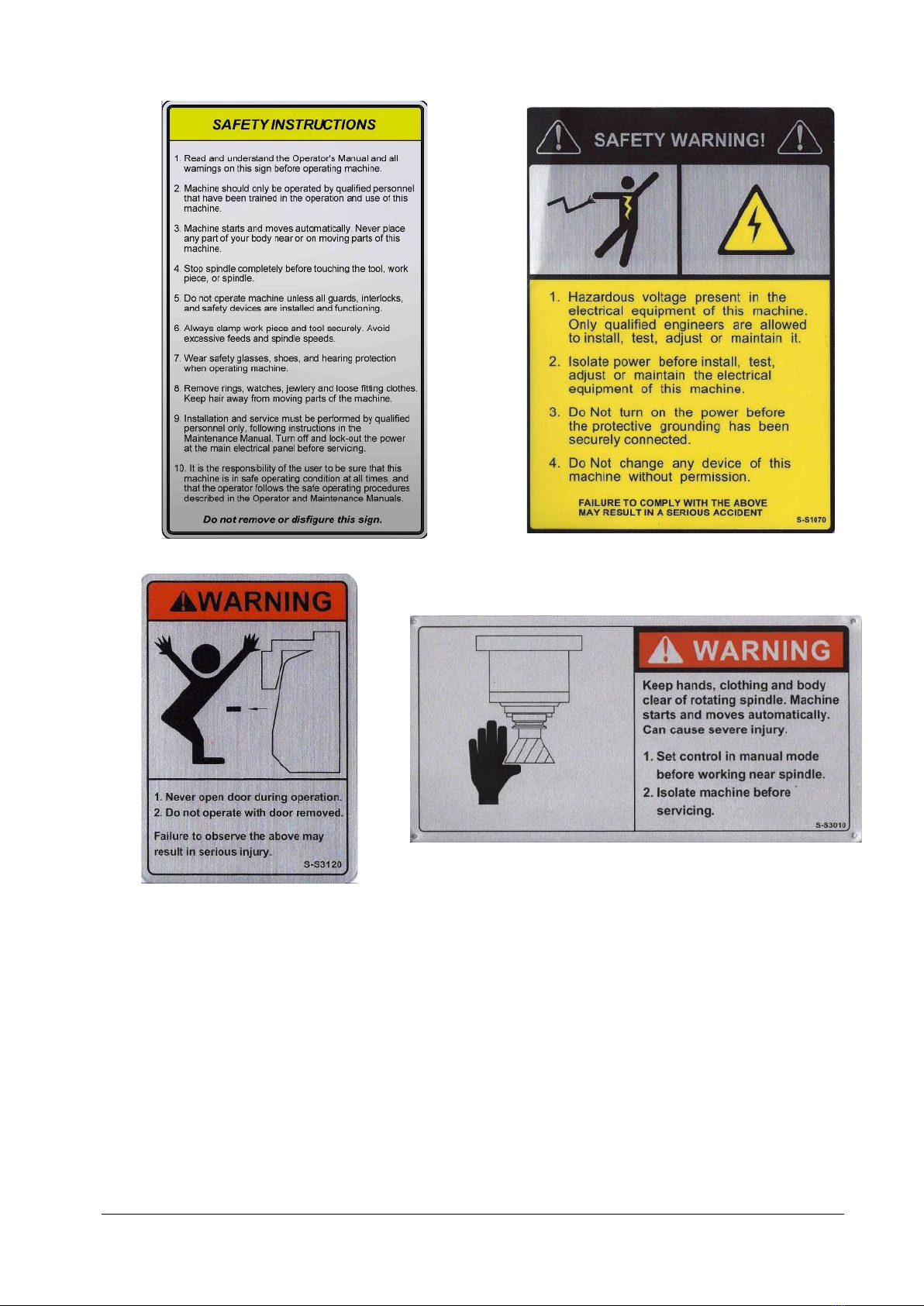
All operators must read and study this manual and the 2 OP Programming, Operating, and Care Manual.
The machine must not be operated until operators understands the operation and safety requirements of
this machine.
This machine must only be operated by trained and experienced operators. Any other users should first be
subjected to a risk assessment by a responsible, trained person.
At the start of each work shift:
•Inspect the guard window for signs of damage or degradation. Replace if necessary or if the
serviceable life has expired, as indicated by the label. Use only mild cleaning agents (such as water-
based detergents) to clean the window. Do not use aggressive solvents. The polycarbonate used for
the window is degraded over time by exposure to cutting fluids. For this reason the replacement
schedule must be adhered to.
•Test the following safety functions. Do not use the machine if the function fails:
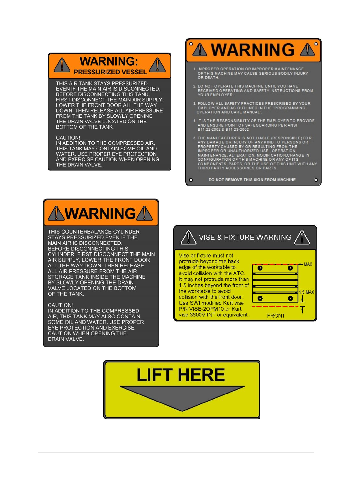
•E-stop (Must stop spindle, axes and de-pressurise the air system – note the reservoir for the
door air assist will NOT be de-pressurised – this must be done manually if undertaking
maintenance work on this system)
•Door guard (spindle must not run with door open).
•Door lock (door must be locked when the spindle is running or during programme RUN).
When operating this machine, always observe the following safety precautions:
•Do not operate this machine without knowing the function of every control key, button,
knob, or handle. Ask your supervisor or a qualified instructor for help when needed.

2
XYZ Machine Tools Ltd
TRAK2
OP
Installation, Maintenance, Service & Part List Manual
•Always wear the appropriate personal protective equipment, including safety glasses and
safety shoes.
•Do not wear loose fitting gloves whilst operating this machine as they could easily get
caught in moving parts.
•Never wear rings, watches, long sleeves, neckties, jewelry, or other loose items when
operating the machine.
•Keep your hair away from moving parts. Wear adequate safety head gear.
•Never operate any machine tool after consuming alcoholic beverages, or taking strong
medications, or while using non-prescription drugs.
•Carry out a COSHH risk assessment and use the correct protection equipment, e.g. barrier
cream/latex gloves, to prevent harm from items such as cutting fluid, lubrication oil and
other substances used on the machine.
•Never run the machine with the enclosure door open
•Observe and understand the warning and safety information labels affixed to this machine.
•Do not attempt to tamper with or override any guarding/safety device fitted to the machine.
•Keep the working area clear and remove all tools (spanners etc.) from the machine before
you start the machine running. Loose items can become dangerous flying projectiles.
•Stop the machine spindle and ensure that the CNC control is in the STOP mode:
oBefore changing tools.
oBefore changing parts.
oBefore you clear away the Swarf, oil or coolant. Always use a chip scraper or brush.
oBefore you make an adjustment to the part, vice, coolant nozzle or take measurements.
oBefore you open guards. Never reach around a guard to gain access to the part, tool, or
fixture.
•Do not use compressed air to remove swarf or clean the machine.
•Keep work area well lit. Ask for additional light if needed.
•Be aware that machine parts can move unexpectedly, so do not lean on the machine while
it is running.
•To prevent slippage and personal injury, keep the working area around the machine dry and
clean. Ensure there is no swarf, oil, coolant and obstacles of any kind around the machine.
•Avoid getting pinched in places where the spindle, table or guard doors create "pinch
points" whilst the machine is in motion.
•Securely clamp and properly locate the workpiece in the vice or in a fixture. Use proper tool
holding equipment.
•Use the correct tooling for the process being undertaken. Never use damaged or worn tools
and ensure the correct cutting parameters (speed, feed, and depth of cut) are used in order
to prevent tool breakage.
•Prevent damage to the workpiece or the cutting tool. Never start the machine (including
the rotation of the spindle) if the tool is in contact with the part.
•Avoid large overhangs on cutting tools when not necessary.
•To prevent fires keep flammable materials and fluids away from the machine, hot swarf and
workpieces.
•Always turn off and lock-out power at the main electrical panel before servicing the machine
•Always turn off and lock out the air supply and depressurise the pneumatic system before
servicing.

3
XYZ Machine Tools Ltd
TRAK2
OP
Installation, Maintenance, Service & Part List Manual
Warning
Pull studs come in a wide variety of designs, however they often look similar and appear to be
interchangeable, but they are not. Use only the knob that the 2 OP mill is designed to use. The use of the
incorrect knob, or the incorrect usage of a knob, may result in injury or equipment damage. To ensure
the correct knob is chosen, please refer to section 2.4.4 of this manual.
1.2 Safety Information Regarding Unpacking the Machine
Please refer to the installation information in section 3
1.3 Safety Information Regarding Moving the Machine On the Pallet Truck
WHEN MOVING THE MACHINE, THE FOLLOWING CONDITIONS MUST BE SATISFIED:
1. Machine moving must only be done by employees who are competent in pallet truck use.
2. The floor must be structurally rated to support the machine (total machine weight without any
accessories is approximately 1200kg).
3. The floor must be relatively flat and with a maximum slope not to exceed 20mm per metre
anywhere along the transportation path.
4. Any steps, gaps or cracks in the floor, must be less than 10mm high, wide, or deep.
5. The minimum door opening for machine to go through is 815 x 2390 mm.
6. Clear a 1250mm wide path for transportation prior to actually moving the machine.
Ensure no one is in front, behind or to the side of the machine when it is on the pallet truck whether
stationary, or being moved.
TO MOVE THE MACHINE, PLEASE FOLLOW THE STEPS BELOW:
1. Move the X-axis to the approximate centre; the Y-axis all the way toward the door (front) until
the (soft) limit is reached; and the Z-axis down until the (soft) limit is reached.
2. Power down, and disconnect the electrical power cable, compressed air hose, and any other
accessory cables/hoses connected to the machine
3. Coil up any cables/hoses remaining connected to the machine and attach securely to the
machine, clear of the floor.
4. Check to make sure that the floor is free of any objects which may obstruct the movement of
the pallet jack wheels or the machine along its transportation path.
5. Roll the pallet jack under the machine, as far as possible. Make sure the trolley jack forks are
aligned with the “Lift Here” labels to ensure the machine is properly balanced. See figure 1.5
6. The machine is actually more stable when lifted from the front or rear, so this is preferred to a
side pick up.
7. Lift the machine about 12 – 15mm off the floor. While pulling, pushing and steering the pallet
jack, monitor the movement of the machine to make sure that it does not run into or catch on
anything during transportation. Carefully move the machine to the new location. WARNING:
Avoid making sudden or sharp turns when moving the machine.
8. Once at the new location, slowly and carefully lower the machine down to the floor, and stow
away the pallet jack.

4
XYZ Machine Tools Ltd
TRAK2
OP
Installation, Maintenance, Service & Part List Manual
Fig. 1.5
1.4 Danger, Warning, Caution, and Note Labels & Notices As Used In This
Manual
DANGER - Immediate hazards that will result in severe personal injury or death. Danger labels on the
machine are red in color.
WARNING - Hazards or unsafe practices that
could
result in severe personal injury and/or damage to the
equipment. Warning labels on the machine are orange in color.
CAUTION - Hazards or unsafe practices, which
could
result in minor personal injury or equipment/product
damage. Caution labels on the machine are yellow in color.
NOTICE- Call attention to specific issues requiring special attention or understanding.
1.5 Safety & Information Labels Used On The TRAK 2 OP Milling Machine
The following safety and information labels are used on the machine.
It is forbidden by law to deface, destroy or remove any of these labels

5
XYZ Machine Tools Ltd
TRAK2
OP
Installation, Maintenance, Service & Part List Manual

6
XYZ Machine Tools Ltd
TRAK2
OP
Installation, Maintenance, Service & Part List Manual

7
XYZ Machine Tools Ltd
TRAK2
OP
Installation, Maintenance, Service & Part List Manual

8
XYZ Machine Tools Ltd
TRAK2
OP
Installation, Maintenance, Service & Part List Manual

9
XYZ Machine Tools Ltd
TRAK2
OP
Installation, Maintenance, Service & Part List Manual

10
XYZ Machine Tools Ltd
TRAK2
OP
Installation, Maintenance, Service & Part List Manual
1.6 Release of Trapped Persons
In the event of a person being trapped, use the electronic handwheel to move the axis in question away
from the operator. If the ATC has trapped the operator, then press the E-stop and push the ATC back
toward the rear of the machine. With the E-stop pressed, air is removed from the ATC cylinder which then
allows you to push it back.
1.7 Noise Levels
The A-weighted emission sound pressure level at the operator’s workstation is less than 70dB(A) (measured
in accordance with EN ISO 11202:1995 and EN 12417:2001+A2:2009, with an uncertainty of 5dB).
1.8 EC Declaration of Conformity
The manufacturer, Southwestern Industries, declares that the 2-OP, M11 mill conforms to all the relevant
provisions of the:
•Machinery Directive 2006/42/EC
•Low Voltage Directive 2014/35/EU, and
•EMC Directive 2014/30/EU
The Technical file is available from XYZ Machine Tools, Woodlands Business Park, Burlescombe, Nr Tiverton,
EX16 7LL, United Kingdom.

11
XYZ Machine Tools Ltd
TRAK2
OP
Installation, Maintenance, Service & Part List Manual
2System Description
2.1 Machine Specifications
Width
775mm
Depth
1321mm
Height with head fully up
2565mm
Minimum height to fit through doorway
2337mm
(Z cable carrier collapsed, resistor cover and resistors removed)
Weight
1280kg
Shipping Weight
1440kg
Table Dimensions
Table size
457mm x 381mm
Number of tee slots and pitch
4 @ 63 mm
Tee slot width
16 mm
Table maximum load
227kg
Ball Lock ® hold down force
1020kg @ 4Nm torque
Travel
X-axis
356mm
Y-axis
457mm (305mm of machining travel)
Z Axis
432mm
Maximum distance from spindle nose to table
surface
514mm
Minimum distance from spindle nose to table
surface
69mm
Maximum swing from spindle centre to column
356mm
Maximum rapid speed (all axes)
15240mm/min
Spindle
Tool holder type
BT30
Spindle nose diameter
56mm
Maximum RPM
6000
Duty Cycle at max RPM
The spindle is not rated for continuous operation at
max RPM. We recommend no more than 4 hours of
continuous running at speeds above 5,000RPM
without a 30 minute rest period.
Automatic Tool Carrier
Tool Capacity
8

12
XYZ Machine Tools Ltd
TRAK2
OP
Installation, Maintenance, Service & Part List Manual
Maximum tool diameter
50mm
Pull stud
See section 2.4.4
Air Requirements
Pressure
90 psi
Quality
Air dried/filtered water separator upstream of the
machine
Maximum demand
100 l/min
18 SCFM
Coolant Capacity
55 litres
Machine Layout (Dimensions in inches)
2.2 Maximum Spindle Torque and Horsepower
The following graphs illustrate the continuous and peak torque vs RPM and horsepower vs RPM for the 2 OP
M11 machine at the spindle. Peak torque and horsepower values can only be attained for a short period of
time before the spindle drive will fault out to protect the motor.

13
XYZ Machine Tools Ltd
TRAK2
OP
Installation, Maintenance, Service & Part List Manual
Note - Maximum work capacities are dependent on a lot of variables that cannot be controlled by the
machine manufacturer. Each one of the following will have an impact on the above numbers: speeds,
feeds, cutter, cutter sharpness, material, setup, coolant and machine adjustments.
2.3 ProtoTRAK TMX Control Hardware
2.3.1 Programming Panel Assembly
The programming panel assembly is mounted to the front right side of the machine.
The panel consists of the program overlay, electronic handwheel (EHW), 5.7” LCD, E-stop and servo on
button. There are 2 USB ports mounted on the right side of the machine next to the programming panel.
They are used to save programs and connect a keyboard and mouse.
There are 7 cables that route from the programming panel to the computer module:

14
XYZ Machine Tools Ltd
TRAK2
OP
Installation, Maintenance, Service & Part List Manual
•VGA cable: Carries video signals from the computer module to LCD controller board.
The LCD interface board gives the user the ability to modify the brightness,
color and position of the image.
•COM port cable Provides a serial communication link between the computer and the Overlay
Interface board.
•overlay power
cable
Provides power to the LCD and Overlay Interface board. Also feeds back the
critical keys (GO, STOP, etc) to the computer module.
•EHW cable. Carriers the signals from the EHW to the computer module.
•Servo On Button Connects one channel of the servo on button to the computer module.
•USB cables (x2) Extend the two, USB ports on the computer module to the USB sockets on
the right side of the machine
A further 2 cables connect the servo on button and E-stop button to the E-stop safety relay in the electrical
cabinet.
2.3.2 Electrical Cabinet
The electrical cabinet is mounted to the rear of the machine. The electrical cabinet contains the main
control hardware for the machine. The main components are the computer module, AC spindle drive and
various fuses and relays. See drawing 27621-5 at the end of the manual.
2.3.3 Computer Module
The computer module is the heart of the machine. All of the inputs and outputs are fed through this
module. The computer module controls the programming panel assembly, AC spindle drive, servo drives,
motor signals and feedback and all the inputs and outputs. The computer module assembly comprises a
computer motherboard, applications board and power supply.
2.3.4 Servo Motors
The TRAK 2OP mill uses 3 servo motors with servo drives to run the X, Y and Z axes. The motors for the X
and Y axis produce 2.4Nm of continuous torque and 7.1Nm of peak torque. The Z axis motor produces
3.2Nm of continuous torque and 9.5 of peak torque. The servo motors run off of 220 volt, single phase
power.
2.3.5 Servo Drives
The TRAK 2OP mill uses 3 servo amps that are mounted in an enclosure that is mounted to the top of the
machine. The servo amps are the same for both the X and Y axis. The Z axis uses a larger servo amp to
drive the larger Z axis motor. A separate braking resistor is part of the Z axis servo amp circuit to dissipate
heat generated when the motor is decelerating. The resistor is mounted to the top of this enclosure.
2.4 Machine Major Sub-Assemblies
2.4.1 Spindle
The spindle is contained within a cartridge. The spindle bearings are permanently lubricated and require no
additional attention by the user. The spindle has an air purge system that is automatically activated during
the tool change sequence; it blows air down the spindle to prevent chips from being trapped between the
holder and spindle taper. The spindle cartridge design is also pressurized by air to prevent contaminants
from getting up inside the spindle. A spindle ring is also attached to the bottom of the spindle via the drive
dogs and prevents debris like coolant from getting up inside the spindle. BT30 tool holders must be used.

15
XYZ Machine Tools Ltd
TRAK2
OP
Installation, Maintenance, Service & Part List Manual
Warning!
The spindle unit is not field serviceable. If the bearings fail, the entire spindle cartridge will
have to be replaced.
2.4.2 Spindle Motor & Drive
The spindle motor is 2.2kW and directly drives the spindle via a coupling. The RPM range is 50 to 6,000
RPM.
2.4.3 Automatic Draw Bar Assembly
The automatic drawbar is an assembly consisting of an air cylinder and an actuator that unclamps the tool.
Tooling is changed by means of the Automatic Tool Changer (ATC), or can be done manually by pressing
and holding the “Unclamp” button. Tools are clamped when the button is released. A clamping force of
approximately 500kg is generated to clamp the toolholder to the spindle. The Automatic Draw Bar Assembly
uses full system air pressure and hydraulic oil and requires no adjustment. There is an oil reservoir for the
hydraulics that should be monitored on a regular basis. If there is a leak in the system, the oil in this
reservoir will go down. This leak will need to be fixed. This oil cup is found on top of the machine behind
the spindle motor.
2.4.4 Pull Studs
The TRAK 2OP Mill uses BT30 pull studs as shown in Figure 2.4.4a. Tightening to the proper torque is
important for all pull studs. Please refer to the manufacturer for the proper torque. You can order a set of
8 pull studs from XYZ Machine Tools under part number 13631. Our pull studs should be torqued to 40Nm.
Figure 2.4.4a
Warning!
Pull studs come in a wide variety of designs, however they often look similar and appear to
be interchangeable, but they are not. Use only the studs the 2 OP mill is designed to use. The
use of the incorrect stud, or the incorrect use of a stud, may result in injury and/or damage
to the mechanism.
2.4.5 Tool Changer (Carrier)
The tool changer is an 8 station mechanism. The ATC mechanism slides forward on the Y axis linear guides
and is actuated via an air cylinder. It is shielded behind a door while the machine is cutting.

16
XYZ Machine Tools Ltd
TRAK2
OP
Installation, Maintenance, Service & Part List Manual
2.4.6 Drive Train, Axes
Each axis (X, Y and Z) rides on precision linear guideways, with four preloaded recirculating ball carriages.
Each axis is moved via a 6 mm pitch ballscrew. The axis motors drive each axis via a timing belt except on
the Z axis where it is directly driven.
2.4.7 Worktable
The 2 OP table utilizes Ball Lock® technology as well as conventional T-bolt construction. The software on
the 2 OP mill allows the user to save the X and Y location of your program relative to the lower left hand
corner ball lock. See the programming manual for more information. There are 4 ball lock receivers
mounted in the table on 300mm centres. The front 2 ball lock receivers are to be used to locate your
fixture and the rear two are for clamping purposes.
Figure 2.4.7a
2.4.8 Home switches
Each axis has a home switch which is used to home the mill. The machine must be homed each time the
control is powered on.
Warning
It is not recommended that the position of the home switches be changed. They are preset
at the factory and should require no additional adjustments. Should any major adjustments
be done, service codes 500, 505, and 520 will need to be performed.
2.4.9 Lubrication System
An automatic, centralised lubricating system is fitted to the 2OP. The pump and reservoir (capacity: 1 litre)
are located on the left side of the machine. While the system is automatic, it is recommended that, after
long idle periods, the machine be manually lubricated by using service code 300. Cycle the lube pump two
or three times. The lubrication reservoir should be maintained on a daily basis, filling only with high quality
lubricating oil. See section 3.3
2.4.10 Coolant and Coolant Wash System
The coolant system uses a single pump to provide coolant to the work and also to wash swarf away from
the area where the ATC comes out. Wash areas can be controlled by the flexible coolant lines found at the
base of the enclosure.
Table of contents