Yaesu G-5400 User manual

Interface for Yaesu G-5400 and G-5600 Antenna-rotators
I started to deal with Earth-Moon-Earth communications in
the middle of 2005. I had to realize, that my two-bay
DJ9BV (2.1 wavelength boom length each) antenna array is
not enough for this mode of communications. It seemed to
be an obvious solution to improve the boom length of the
existing antennas which are otherwise consisting of mod-
ules. Unfortunately, after modifying the antennas it became
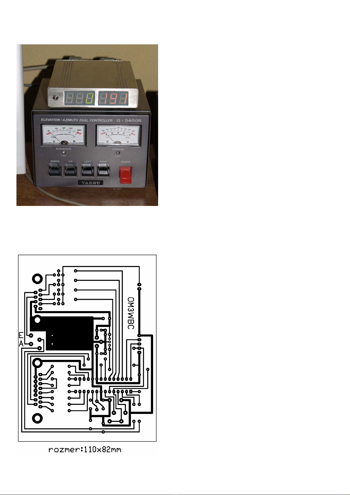
evident, the original display solution using Deprez meters
can not meet the new requirements. To solve this problem
this interface was born, which beside the exact display
makes it possible to rotate the antenna by computer control,
so it is a great help in providing satellite communications as
well. Those who use shorter antenna for satellite tracking
only, can build the interface without digital display. The
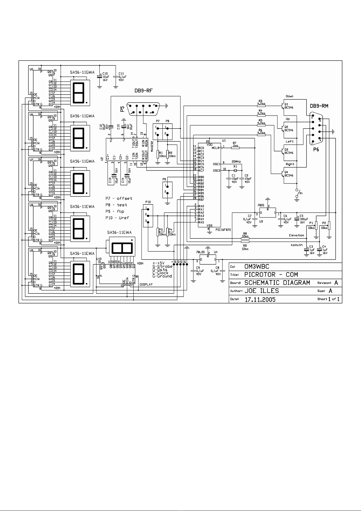
interface was made in two versions. One of them makes use
of a parallel port the other uses a serial port for communica-
tions with the rotator. Both solutions have advantages and
disadvantages. The version making use of a parallel port
has a great disadvantage because the port can handle eight
bits only; hence the best possible definition is 1.4 degree.
On the other hand, while the serial ports are generally in
use for different communication purposes, parallel ports are not utilized i.e. later printer models are made for
USB ports. The base of both versions is a PIC16F870 microprocessor which includes a ten-bit A/D converter
and a serial port driver too.
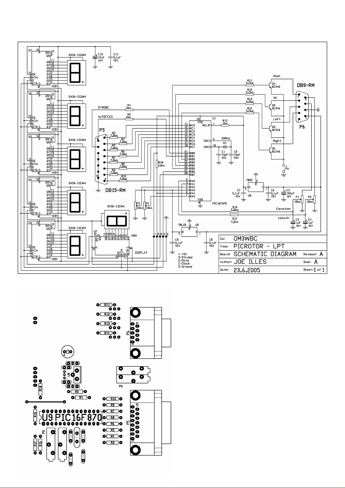
Interface for the parallel port
Operation
This interface uses the protocol of the FODTRACK pro-
gram. This driver can be freely downloaded from the Inter-
net. Latest software like WXTRACK is able to handle an
interface like this, by default. The co-ordinates of azimuth
and elevation are calculated in eight bit accuracy. AUTO-
FEED output decides which data is active at a given time.
The high level output of STROBE shows the validity of
data. The processor continuously checks STROBE signal
and in its active state it decides depending on the level of
AUTOFEED signal, whether data is to be applied as azi-
muth or as elevation. According this, it puts data into a
variable. In case the content of variables does not corre-
spond with the momentary position of the antenna then it
gives an instruction to turn the antenna until it reaches the
required position. In this version the maximum elevation of
the antenna can be 90 degrees. The FLIP function of satel-
lite-tracking software is disabled. To turn the antenna into a
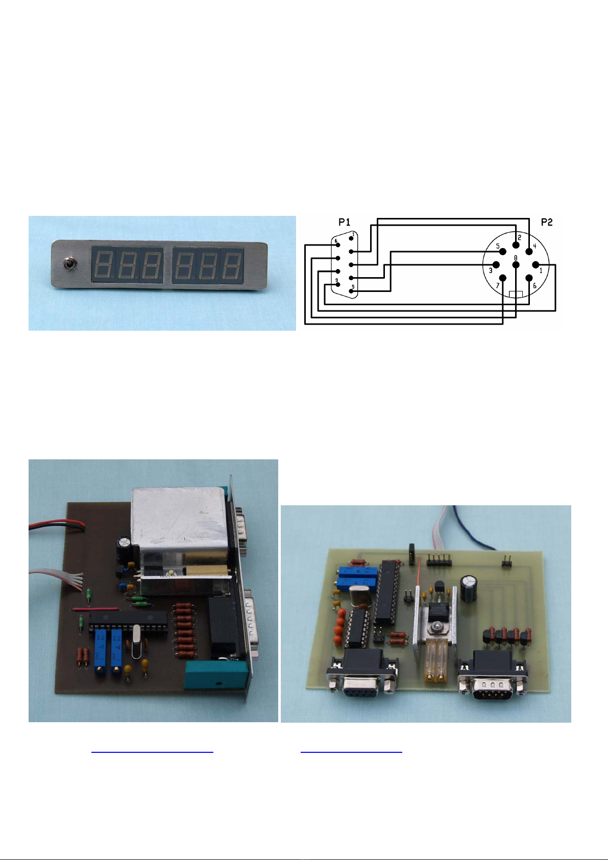
position exactly without climbing the tower or mast, the
interface is equipped with two variable resistors to make it
possible to correct the difference between the displayed
values and the real position of the antenna. These adjust-
ments can be done by connecting STROBE and AUTO-
FEED inputs to low logic level before the interface is

switched on. Then variable resistors P3 and P4 can be adjusted to the required shift in both horizontal and verti-
cal plane.
Construction
Make ready the single sided PCB which is not too
complex so it can be done in your home workshop.
After placing and soldering components check whe-
ther voltage regulators are functioning properly. If
yes, then adjust all variable resistors into middle posi-
tion and start with final adjustments.
Interface for serial ports
Operation
In case we are intended to use a serial port instead of
a parallel port we have to adjust voltage levels prop-
erly. For this task a well known circuit MAX232 can
be used. Since the change to a serial port we can save
some connections on the microprocessor. In this case
we can decide ourselves whether to utilize FLIP func-
tion (PORTB, 0-P9) and for adjusting the necessary
shift it is enough to take a short circuit to the right
place (PORTC, 4-P7). Beside these, we can test com-
munications between PC and interface if we put the

the short circuit into P8 position. In this case we do not turn the antenna. The value on the display is that volt-
age which is calculated by the computer. The processor needs this value from the antenna-rotator. For full scale
deflection 3.6 Volts are necessary on both inputs. Use the CX6DD.COM (GS232) driver for communication.
The necessary parameters are 9600 Bd, 8N1.
Construction
The PCB is similar to the previous one. It’s not too complicated to produce. For providing the necessary supply
and reference voltages, we use two voltage regulators but for the sake of simplicity, the reference voltage regu-
lator can be omitted and the voltage source of the main regulator can be used for this purpose. Depending on
the factory of MAX232 it can happen that the inverter inside of the circuit does not work properly. In this case
we have to use tantalum capacitors – or depending on the production technology smaller capacitor values can
be chosen which may be as low as 100 nF for a CMOS product. In case of appropriate operation on pin 2 of
MAX232 +9.4 V, while on pin 6 -9.4 V must be measured. If the voltages are equal to these values adjust the
variable resistors into middle position.
Display
Operation
It is connected to the processor by three data lines using serial data transfer. The circuit contains six shift regis-
ters which convert serial data coming from the processor to parallel data for the LED displays. Operation is as
follows: Data arriving to the input is shifted by the clock signal continuously one place forward in the register.
When all the 48 bits are on the right place the strobe signal copies data to the output of the register. The advan-
tage of this method to the widely used multiplex method is that the light intensity of the displays is higher and
they do not vibrate.

Construction
Production of the PCB is a greater challenge. The drawing of the panel is much more complex and denser than
the previous ones. It was successful to produce this PCB using the so called “blue-foil” technology. Other
photo-resistive sprays like Positiv-20 can also be used. Check the PCB thoroughly before placing components
because it would not be possible to repair foil under integrated circuits. Shift registers are placed onto the foil
side while LED displays are to be inserted onto the component side.
Final adjustments
Final adjustments are similar in case of both versions. First step is to adjust the two variable resistors named
„OUT VOLTAGE ADJUST” on the back side of the rotator to produce maximum voltage on the connector.
Start with the adjustment of the shift. Connect the interface to the original controller of the rotator. The drawing

of the connecting cable can be seen below. Before switching the unit on connect together pin 9, 10, 11 in the
PC-connector. In case of serial port put a short circuit to P7. When everything is all right, then a number will
appear on the display which is between +16 and -16 both as azimuth and as elevation. If not, we must have
done something wrong on the PCB of the display or we did not connect the main board and the display prop-
erly. Adjust zero value by P3 and P4 variable resistors. (Now we do not take into account the real position of
the antenna.) Cut the short circuit. Then values will appear on the display according to the position of the an-
tenna. Turn the antenna into default position. The display will show 0 and 180 respectively. Now check the
direction of the antenna optically. Mark this direction as precisely as we can. Turn around the antenna to point
into the same direction as in default position. Now adjust 180 degrees azimuth by P2 again. Then we will have
finished horizontal adjustments. In the vertical plane the procedure is the same but the display must show 0 in
default position and 180 in the end position (P1). We will than have basic adjustments finished. If the antenna
does not point to the direction shown on the display we can correct shifts by variable resistors P3 and P4.
Final notes
This interface has been built for Yaesu rotators but there is no reason not to use it with rotators of other makes.
The single condition is that there must not appear higher voltage than 5V on analog input and the relay used in
the rotator must not consume more power than the transistors can withstand without failure. Of course their
power rating can be properly chosen according to the requirements hence they can be different to those on the
circuit diagrams. The aforementioned software can be obtained freely on the Internet.
WXTRACK http://www.satsignal.net , FODTRACK – http://qsl.net/xq2fod
The content of PIC16F870 can be found in ZIP-file
This manual suits for next models
1
Table of contents
Other Yaesu Antenna manuals
Popular Antenna manuals by other brands

One Forall
One Forall SV-9320 instruction manual

One Forall
One Forall SV-9320 instruction manual

Comet Antenna
Comet Antenna HFJ-350M instruction manual

NXP Semiconductors
NXP Semiconductors PN5180 Design guide

Steren
Steren ANT-UHF 16 instruction manual

Sirius XM RAdio
Sirius XM RAdio NGVA1 installation guide

Honeywell
Honeywell GSM-ANT Technical Support Help Doc

Atmel
Atmel ATA5278 manual

Cisco
Cisco AIR-ANT2544V4M-R Specification and user manual

tactio
tactio LAXO-AN-PG21 installation guide

Dormakaba
Dormakaba BEST BACKSIDE ANTENNA KIT installation instructions

Cradlepoint
Cradlepoint 170605-000 installation guide