Yaesu FT-4XE User manual

VHF/UHF
DUAL BAND FM TRANSCEIVER
FT- 4XR
FT- 4X E
Advance Manual
Clicking (tapping) at the at the bottom left of the current browsing page,
will return to the contents page at any time.

Contents
Communicating with specified other station ..................................4
Selecting the Squelch Type ...........................................................4
Tone squelch feature .....................................................................5
Setting CTCSS Tone frequency ..................................................5
Digital Code Squelch (DCS) feature..............................................6
Setting the DCS CODE............................................................... 6
New Two CTCSS Tone Pager Function ........................................7
Using the Pager Function ...........................................................7
Setting the Code for Your Station................................................ 7
Calling a Specific Station ............................................................8
Receiving “pager code” calls from a
Remote Station (Standby Operation).......................................... 8
Using the Pager Answer Back ....................................................8
Notification of a Call from a Remote Station by the Bell Function
... 9
Convenient Functions..................................................................10
VOX Operation ............................................................................10
VFO Split Mode ...........................................................................10
Split Memory................................................................................10
Using Memory Tag....................................................................... 11
Changing between name tag display and
frequency display (Memory Tune)............................................. 11
The Memory Channel Only Mode................................................12
Canceling Memory Only Mode.................................................. 12
Using Memory Banks ..................................................................13
Registering to Memory Banks...................................................13
Memory Bank Recall.................................................................14
Returning To Memory mode from Memory Bank operation ...... 14
Removing a Memory channel from a Memory Bank................. 14

Contents
How to Skip (Omit) a Channel during Memory Scan Operation
... 14
Programmable Memory Channel Scan (PMS) ............................15
Registering to the Programmable Memory Channels ...............15
Performing Programmable Memory Channel Scan .................. 15
Dual Receive (DW) Function....................................................... 16
Activating the Dual Receive (DW) feature ................................16
Priority Revert Mode .................................................................17
ARTS (Automatic Range Transponder System).......................... 18
Basic ARTS Setup and Operation............................................. 18
ARTS Polling Time Options ......................................................19
ARTS Alert Beep Options ......................................................... 19
CW Identifier Setup................................................................... 19
DTMF Operation..........................................................................20
Setting the DTMF Memory........................................................20
Transmitting the Registered DTMF Code ................................. 21
Manually Transmitting the DTMF Code .................................... 21
Customizing Menu Settings and User Preferences (Set Mode)
... 22
Setting the Set Mode...................................................................22
Tables of Set Mode Operations ...................................................23
Cloning ........................................................................................33
Troubleshooting........................................................................... 34

4
Communicating with specified other station
Selecting the Squelch Type
Press and hold
the Function key →Press the por qkey →Press the Function key
(Entering the Set Mode)
(Selecting the 36 SQL.TYP)
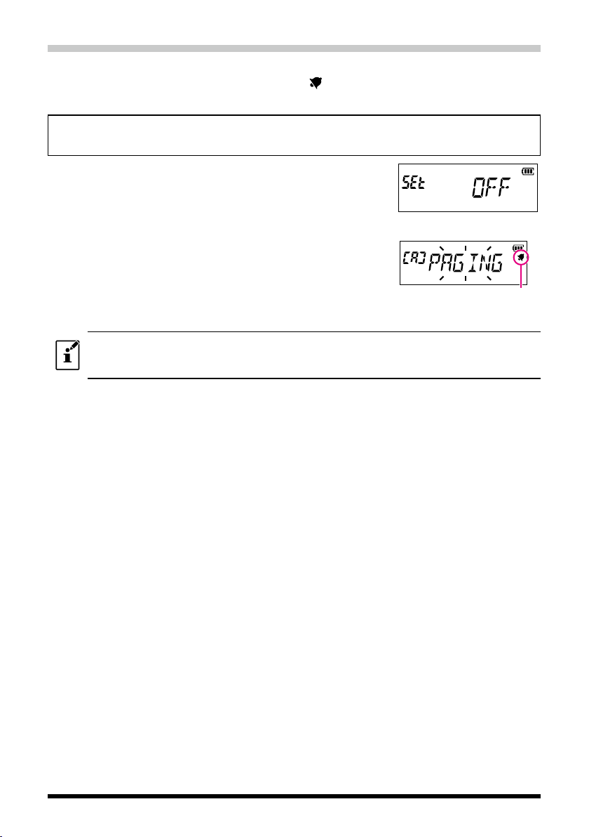
1. Press the [▲] or [▼] key to select one of the modes described below.
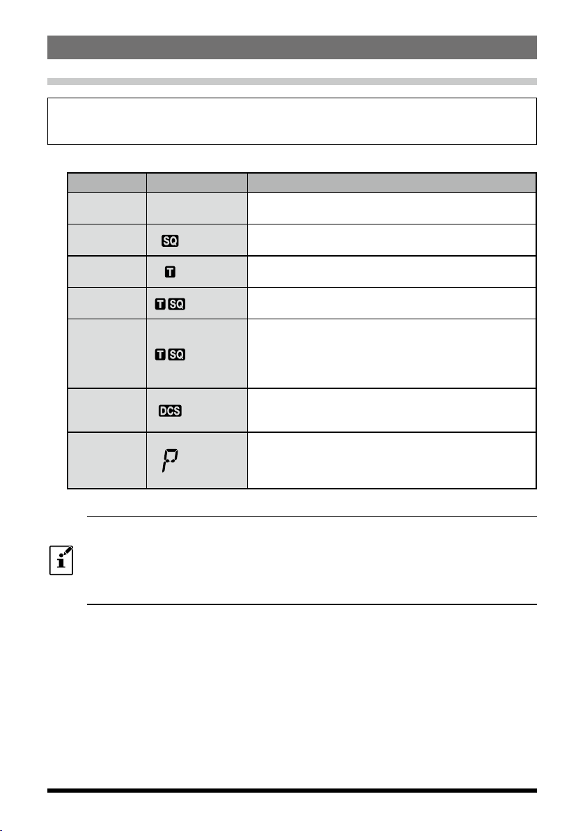
Squelch type Icon indication Description
OFF
(default)-Deactivates the tone squelch function and DCS function
OFF, then returns to the normal squelch operation.
R-TONE (appears) Enables receive only tone squelch function.
T-TONE (appears) Enables transmit only tone squelch function.
TSQL (appears) Enables the tone squelch receive function.
REV TN (blinks)
Enables the reverse tone squelch function.
Use to monitor communications based on the squelch
control system in which a received signal containing the
selected tone will be muted, and signals not containing
the selected tone will be heard.
DCS (appears)
Enables the digital code squelch function.
The DCS code may be selected from 104 codes (from
023 to 754).
PAGER (appears)
Activates a new two-tone CTCSS pager function.
When communicating via transceivers with your friends,
specify personal codes (each code is composed of two
tones) so that you can call only specific stations.
2. Press the PTT switch to save the new setting and return to normal operation.
zThe squelch type may be set for each frequency band (BAND).
zThe CTCSS and DCS squelch settings are also active during scanning. If scanning is
performed with the CTCSS and DCS squelch function activated, scanning stops only when a
signal containing the specified CTCSS tone or DCS code is received.
zPressing the MONI/T-CALL switch allows signals that do not contain a tone or DCS code, and
signals with different tones, DCS codes to all be heard.

5
Tone squelch feature
The tone squelch opens the speaker audio only when a signal containing the specified
CTCSS tone is received. The receiver will be quiet while waiting for a call from a specific
station.
Setting CTCSS Tone frequency
The tone frequency may be selected from 50 frequencies (from 67.0 Hz to 254.1 Hz).
Press and hold
the Function key →Press the por qkey →Press the Function key
(Entering the Set Mode) (Selecting "36 SQL.TYP")
1. Press the [p] or [q] to select the “TSQL”
2. Press the Function key.
3. Press the [p] or [q] to select the “38 TN FRQ”.
4. Press the Function key.
• The receive (R) tone frequency setting screen will appear.
5. Press the [p] or [q] to select the receive (R) tone fre-
quency.
• Pressing the [ V/M] key to switch to the transmit (T)
tone frequency, then press the [p] or [q] to select the
transmit (T) tone frequency. Receive
6. Press the PTT switch to save the settings and return to normal operation.
zThe tone frequency setting is common with the squelch types as follows:
R-TONE, T-TONE, TSQL, RV TN
zThe default setting is “100.0Hz”.

6
Digital Code Squelch (DCS) feature
The Digital Code Squelch opens the speaker audio only when a signal containing the
specified DCS code is received.
The DCS code may be selected from 104 types (from 023 to 754).
Setting the DCS CODE
Press and hold
the Function key →Press the por qkey →Press the Function key
(Entering the Set Mode) (Selecting "36 SQL.TYP")
1. Press the [p] or [q] to select the “DCS”
2. Press the Function key.
3. Press the [p] or [q] to select the “10 DCS.COD”.
4. Press the Function key.
• The receive (R) DCS code setting screen will appear.
5. Press the [p] or [q] to select the receive (R) DCS code.
• Pressing the [ V/M] key to switch to the transmit (T)
DCS code, then press the [p] or [q] to select the
transmit (T) DCS code.
Receive
6. Press the PTT switch to save the settings and return to normal operation.
The default DCS code is “023”.

7
New Two CTCSS Tone Pager Function
When using the FT-4XR/XE transceivers with a group of friends, setting the two CTCSS
tone personal codes allows calling just the specific stations.
Using the Pager Function
Press and hold
the Function key →Press the por qkey →Press the Function key
(Entering the Set Mode) (Selecting "36 SQL.TYP")
1. Press the [p] or [q] to select the “PAGER”.
2. Press the PTT switch to save the setting and return to
the normal operation.
• The new pager function is activated.
PAGER icon
Setting the Code for Your Station
Set the “pager code” to be called by other stations.
Press and hold
the Function key →Press the por qkey →Press the Function key
(Entering the Set Mode) (Selecting "23 PAG.CDR")
1. Press the numeric key to input the first element of the
code from 01 to 50.
• The icon is moved to the second element of the code.
2. Press the numeric key to input the second element of
the code from 01 to 50.
• The first and second element of the code may not be
set to the same code.
• Press the [p] or [q] to switch the icon between first
code and second code.
3. Press the PTT switch to save the setting and return to normal operation.
zThe reverse combination works as the same code, that is “05 47” is the same as “47 05”.
zIf the same code is specified for all individuals, all the individuals can be called at the same
time.
zThe default code is “05 47”.
zWhen receiving the signals, the intermittent sound of the tone signal may be heard slightly.

8
Calling a Specific Station
The “pager code” may be set to call to specific stations.
Press and hold
the Function key →Press the por qkey →Press the Function key
(Entering the Set mode) (Selecting "24 PAG.CDT")
1. Press the numeric key to input the first element of the
code from 01 to 50.
• The icon is moved to the second element of the code.
2. Press the numeric key to input the second element of
the code from 01 to 50.
• The first and second element of the code may not be
set to the same code.
• Press the [p] or [q] to switch the icon between first
code and second code.
3. Press the PTT switch to save the setting and return to normal operation.
4. Press the PTT switch to transmit a call to the specific station.
Receiving “pager code” calls from a Remote Station (Standby Operation)
When the Pager function is activated, and a call is received with a corresponding Code,
“PAGING” blinks and the audio is heard.
Furthermore, when the Bell function ( 9) is activated, the bell rings and the icon
blinks while calling from the other station.
Using the Pager Answer Back
If the Answer Back feature is ON, when called by another station with a corresponding
pager code, the transceiver is automatically placed in the transmit mode (for about 2.5
seconds) to notify the other station that you are ready to communicate.
Press and hold
the Function key →Press the por qkey →Press the Function key
(Entering the Set Mode) (Selecting "22 PAG.ABK")
1. Press the [p] or [q] to select the “ABK.ON”.
2. Press the PTT switch to save the setting and return to normal operation.

9
Notification of a Call from a Remote Station by the Bell Function
The Bell may be set to sound an Alert when a call from another station containing a corre-
sponding tone, DCS or pager code is received.“ ”icon on the LCD blinks while the sound
alerts.
Press and hold
the Function key →Press the por qkey →Press the Function key
(Entering the Set Mode) (Selecting "6 BELL")
1. Press the [p] or [q] to select the desired number of
times (1-8 times or continuous) the Bell rings.
• • • OFF 1T 3T
5T 8T CONT (continuous) • • •
2. Press the PTT switch to save the setting and return to
normal operation.
BELL Icon
Example of New PAGER function
zThe default setting is “OFF”.
zIf setting the “CONT” (continuous), the bell keeps sounding until operating something.
zIf “OFF” is set in the Set Mode “5 BEEP”, the bell does not sound.

10
Convenient Functions
VOX Operation
The VOX (Voice Over Transmit) system provides automatic transmit/receive switching
based on voice input without pressing the PTT switch in order to transmit. The optional
SSM-512B VOX Earpiece Microphone is supported.
Press and hold
the Function key →Press the por qkey →Press the Function key
(Entering the Set Mode) (Selecting "43 VOX")
1. Press the [p] key or [q] key to select the “VOX ON”.
2. Press the PTT switch to save the setting and return to
normal operation.
• When the VOX system is activated, the “ ” icon will
appear on the display.
Connecting to the SSM-512B VOX Earpiece Microphone, refer to the supplied SSM-512B manual
sheet.
VFO Split Mode
Two different frequencies, one for receive (VFO-A) and another for transmit (VFO-B),
may be transmitted and received (or vice versa).
Press and hold
the Function key →Press the por qkey →Press the Function key
(Entering the Set Mode) (Selecting "42 VFO.SPL")
1. Press the [p] or [q] to select the “VSP. ON”.
2. Press the PTT switch to save the setting and return to normal operation.
3. Set VFO-A for the desired receiving (downlink) frequency.
4. Press the [ V/M] key to set VFO-B for desired transmit (uplink) frequency.
5. Press the [ V/M] key twice to re-establish VFO-A as the “Main” (receive) VFO.
6. When the PTT switch is pressed to transmit, VFO-A and VFO-B will reverse posi-
tions. Releasing the PTT switch, the reverse position is canceled.
Split Memory
Two different frequencies, one for receive and another for transmit, may be registered to
a memory channel.
1. Register the receive frequency to a memory channel first.
See “Registering to Memory Channels” (Operating Manual).
2. Set the transceiver to the desired transmit frequency.
3. Press and hold the [ V/M] key.
• A blank memory channel will be displayed automatically.

11
4. Press the [p] key or [q] key to select the memory channel number registered in
step 1.
5. Press the [P2] key.
• The beep sounds, Split memory channel is registered.
• While recalling the Split memory channel,
“ ” and “ ”
will appear.
Semi-Duplex Memory Display
6. Press the PTT switch to save the setting and return to
normal operation.
While operating the Split Memory, press the Function key, then press the [P2] key to reverse the
transmit and receive frequencies temporarily. When reversing the frequencies,
“ ” and “ ” blink.
Using Memory Tag
Memory name tags (up to 6 characters) may be assigned or changed on the memory
channels or PMS memory channel.
1. Press the [ V/M] key to recall the memory channel to assign the name tag.
2. Press and hold the function key, then press the
[p] key or [q] key to select the Set
Mode “
21 MEM.TAG
”.
3. Press the Function key.
The character input screen is displayed.
4. Use the numeric key to input the characters.
• Inputting characters
Example quickly Pressing the [2] key, each time switches the following characters:
2 → A → B → C → a → b → c → 2 →
・・・
• Moving the cursor
[p] key: Moves the cursor to the right
[q] key: Moves the cursor to the left
5. Press and hold the Function key.
• The memory tag is registered to the Memory Channel and return to upper Set
Mode item.
6. Press the PTT switch to return to the Memory Channel mode.
The memory name tag registered to the channel is automatically displayed as the memory tag
indication.
Changing between name tag display and frequency display (Memory Tune)
The memory tag display may change the frequency display temporarily and tune off
temporarily (Memory Tune).
1. Recall the Memory channel to be changed.
2. Press the [#BAND] key.
“tun” will appear and the [#BAND] key will toggle between the Memory tag and the
frequency display. During the frequency display, Press the [p] key or [q] key to tune
to the desired frequency.

12
The Memory Channel Only Mode
The FT-4XR/XE may be set to operated only in the registered memory channels.
1. Press and hold the MONI/T.CALL key and the PTT switch simultaneously, while turn-
ing the transciever ON.
2. Press the [▲] or [▼] key to select the “F5 M-ONLY”.
3. Press the Function key.
• The memory channel only mode is ON, the previously selected memory channel is
recalled.
• Pressing the [▲] or [▼] key may be selected the memory channel.
• Inputting the 3 digits of the memory channel using the numeric keys may be re-
called the memory channel directly.
zIn the memory only mode, the following functions will not operate:
• Changing the VFO mode (Press the
[V/M]
key)
• Memory Tune (Press the [#BAND] key)
• Program Memory scan (Press the Function key, and then press the [#BAND] key)
• Recalling the Home channel
• Reverse function (Press the Function key, and then press [P2] key)
• DTMF autodialer setting
zIn the memory only mode, press the Function key to change the squelch level.
zIn the memory only mode, press and hold the Function key to change the transmit output level.
Canceling Memory Only Mode
1. Turn the transceiver OFF, and then press and hold the MONI/T.CALL key and the
PTT switch simultaneously to, while turning the transceiver ON again. The memory
channel only mode OFF.

13
Using Memory Banks
The transceiver allows using up to 10 memory banks to be recalled with the sorted the
memory channels. One memory channel may also be registered in two or more memory
banks according to the intended use.
Example of registering memory channels to the memory banks:
Memory Channel
CH 001 430.000 MHz
CH 002 145.500 MHz
CH 003 435.000 MHz
CH 004 435.500 MHz
CH 005 145.800 MHz
CH 006 436.000 MHz
CH 007 108.000 MHz
CH 198 145.620 MHz
CH 199 436.780 MHz
CH 200 87.500 MHz
Memory Bank “5”
FM Broadcast Band Channels
Memory Bank “4”
ClubChannels
Memory Bank “3”
All Amateur Band Channels
Memory Bank “1”
144 MHz Amateur Band Channels
Memory Bank “2”
430 MHz Amateur Band Channels
Registering to Memory Banks
1. Press the [ V/M] key to enter the memory mode.
2. Press the [▲] or [▼] key to recall the memory channel to
register in the memory bank.
Memory Channel
number
3. Press and hold the [#BAND] key.
“SEL” blinks.
4. Press the [▲] or [▼] key to select the the memory bank
(BANK 1 to BANK 10) to register the memory channel.
• Blinking Bank number is assignable.
5. Press and hold the Function key.
The memory channel is registered to the Memory Bank
and the blinking Bank Number stops blinking.
Memory Bank Number
6. Press the PTT switch to return to the memory channel.

14
Memory Bank Recall
1. Press the [ V/M] key to enter the Memory Mode.
2. Press and hold the [#BAND] key, then press the [▲] or [▼] key to select the desired
Memory Bank (“BANK 1” through “BANK10”).
3. Press the [ V/M] key.
• Only memory channels assigned in the current memory Bank will be available.
• When the multiple memory channels are assigned in one memory bank, press the
the [▲] or [▼] key to select the desired memory channel.
• The “ ” indication will appear at the left side of
the frequency display while operating within a Mem-
ory Bank.
• The memory channel number appears above the
“” icon.
• To change to another Memory Bank, press and hold the [#BAND] key.
Returning To Memory mode from Memory Bank operation
1. While in the Memory Bank Mode, press and hold the
[#BAND] key, and then press the [▲] or [▼] key to select
“NO BANK”.
2. Press the [ V/M] key to return to Memory Mode.
Removing a Memory channel from a Memory Bank
1. Recall the Memory Bank that contains the memory channel to delete.
2. Press the [▲] or [▼] key to select the Memory channel to delete, then press and
hold the [#BAND] key.
3. Press and hold the Function key to remove the memory channel.
• If assigned memory channels still remain in the Memory Bank, the display will re-
turn to a Memory Bank channel.
• If there is no assigned memory channel in the Memory Bank, the display will return
to the Memory mode.
How to Skip (Omit) a Channel during Memory Scan Operation
The “Skip Memory Channel” may be skipped during the memory scanning. When the
“Skip Memory Channels” is set, the specified memory channels may be skipped during
the memory scanning.
1. Recall the memory channel to specify.
2. Press and hold the Function key, then press the [▲] or [▼] key to select Set Mode “35 SKIP”.
3. Press the Function key.
4. Press the [p] or [q] to select the “SKIP”
5. Press the PTT switch to return to normal operation.
• The “u” icon will appear above the memory channel
number, indicating it is to be ignored during scanning.

15
Programmable Memory Channel Scan (PMS)
Registering to the Programmable Memory Channels
10 sets of PMS memory channels (L01/U01 to L10/U10) are available.
Register the lower and upper frequencies of the frequency range in a pair of Program-
mable Memory Channels,
L□□: Lower limit memory channel
U□□: Upper limit memory channel
For more details on registering frequencies to the memory channel, see the operating
manual.
zMake sure to use the corresponding numbers for the lower and upper limit memory channels.
zSet the PMS memory channel for performing the Programmable Memory scanning (PMS) as
follows.
•The scan width of the upper and lower limit frequencies must be 100 kHz or more.
•The lower and upper limit memory channels must be within the same frequency band.
•The lower and upper limit memory channels must not register the lower and upper channels
in reverse.
Performing Programmable Memory Channel Scan
The programmable memory channel scan allows scanning a specified frequency range
within the same frequency band.
1. Press and hold the [#BAND] key.
2. Press the [▲] or [▼] key to select the “PMS-□”.
• “PMS-□” will change depending on the currently-selected PMS frequency pair.
3. Press the PTT switch to return to normal operation.
4. Press the Function key, then press the [#BAND] key.
The scanning starts just within the programmed range.
• During scanning, “P-□” appears on the upper left side of the LCD.
• If the scanner halts on an incoming signal, the back light will turn ON and the dec-
imal point between the “MHz” and “kHz” digits of the frequency display will blink.
Scanning will resume in about two seconds.
5. Press the PTT switch to cancel the scanning.

16
Dual Receive (DW) Function
The transceiver is equipped with the following 3 types of Dual Receive Functions:
VFO Dual Receive
Memory Channel Dual Receive
Home Channel Dual Receive
The transceiver checks for signals on the frequency registered to the selected memory
channel (Priority Memory Channel) once approximately every 5 seconds. When receiv-
ing a signal on the frequency registered to a priority memory channel, the Dual Receive
function temporarily pauses, and allows reception of the signals.
Example: Checking the priority memory channel “1” (145.000 MHz), while receiving
“432.500 MHz”.
VFO Priority
Memory Channel
The transceiver monitors signals
on the frequency registered to the
Priority Memory Channel, once
approximately every 5 seconds.
When the transceiver
receives a signal on the
frequency registered to the
priority memory channel,
dual reception stops and
signal receiver switches to
priority memory channel.
The transceiver returns to the
previous frequency quickly and
continues to receive mode when
there is no signal.
Dual Receive Icon Priority Memory Channel Icon
Activating the Dual Receive (DW) feature
1. Press the [ V/M] key to set the memory channel “1” (the Priority Memory Channel)
to receive.
2. Set the frequency and communication mode to monitor continually.
• The monitor frequency may be set on the VFO mode, the memory channel mode
or the HOME channel mode.
VFO Dual Receive VFO Priority Memory Channel
Memory Channel Dual Receive Memory Channel Priority Memory Channel
HOME Channel Dual Receive HOME Channel Priority Memory Channel
When using the Memory Channel Dual Receive, register the Priority memory channel to the
Memory channel number “1”. the Memory Bank feature also checks the Memory channel number
“1”.
3. Press the Function key, then press the [ V/M] key.
• “DW” icon appears and the Dual Receive function ac-
tivates.
4. Press the [ V/M] key to cancel the Dual Receive func-
tion.

17
Priority Revert Mode
During the Memory Channel Dual Receive operation, press the PTT switch to transmit
the specified priority memory channel.
Press and hold
the Function key →Press the por qkey →Press the Function key
(Entering the Set mode) (Selecting "25 PRI.RVT")
1. Press the [▲] or [▼] key to select “RVT ON”.
2. Press the PTT switch to save the setting and return to the normal operation.

18
ARTS (Automatic Range Transponder System)
The ARTS feature uses DCS signaling to inform both parties when another ARTS
equipped station is within communications range. This may be particularly useful during
Search and Rescue situations, where it is important to stay in contact with the other
members of the group.
The stations must set up their DCS codes to the same code number, and then activate
their ARTS feature using the command appropriate for their transceiver. Alert ringers
may be activated, if desired.
Whenever the PTT switch is pressed, or every 15 or 25 seconds after ARTS is activated,
the transceiver will transmit a signal which includes a (subaudible) DCS code for about
one second. If another ARTS enabled transceiver is in range, the beeper will sound and
the display will show “IN.RNG”. When the other transceiver is out of range, “OUT.RNG”
is shown when the ARTS function is in operation.
Whether or not the PTT switch is pressed, the transceiver
may be programmed to transmit a CW ID, every 10 min-
utes.
If you move out of range for more than one minute (four pollings), the transceiver will
sense that no signal has been received, three beeps will sound, and the display will re-
vert to “OUT.RNG” If you move back into range, the transceiver will again beep, and the
display will change back to the “IN.RNG” indication.
During ARTS operation, it is not possible to change the operating frequency or other set-
tings. In order to resume normal operation, ARTS must be terminated. This is a safety
feature designed to prevent accidental loss of contact due to channel change, etc.
Basic ARTS Setup and Operation
1. Set all the transceivers to the same DCS code number, per the instructions on page
6.
2. Press and hold the [2] key.
• ARTS polling will starts.
• “OUT.RNG” will be displayed on the LCD.
3. Every 25 seconds, the transceiver will transmit a “polling” call to the other station.
• When that station responds with its own ARTS polling
signal, the display will change to “IN.RNG” to confirm
that the other station’s polling code response was re-
ceived.

19
4. Press the Function key (or press and hold the [2] key) to exit ARTS operation and
resume normal transceiver operation.
ARTS Polling Time Options
The ARTS feature may be programmed to poll every 25 seconds (default setting) or 15
seconds. The default setting provides maximum battery conservation, because the poll-
ing signal is sent out less frequently.
Press and hold
the Function key →Press the por qkey →Press the Function key
(Entering the Set mode) (Selecting "3 AR INT")
1. Press the [▲] or [▼] key to select the desired polling
interval (15 or 25 seconds).
2. Press the PTT switch to save the new setting and return to normal operation.
ARTS Alert Beep Options
The ARTS feature permits two types of alert beeps (or may be turned off).
Display Description
OFF(Default setting) No beeps.
INRANG
Beeps sound only when the transceiver rst conrms a station is with-
in range, but does not re-conrm with beeps thereafter. Display is the
same function as “OFF”.
ALWAYS Each time a polling transmission is received from the other station,
the alert beeps will sound. Display is same function as “OFF”.
Press and hold
the Function key →Press the por qkey →Press the Function key
(Entering the Set mode) (Selecting "2 AR BEP")
1. Press the [▲] or [▼] key to select the above type.
2. Press the PTT switch to save the new setting and return to normal operation.
CW Identifier Setup
The transceiver may be programmed to send a CW identification (e.g. call sign) every
ten minutes during ARTS operation. The call sign field may contain up to 6 characters.
Press and hold
the Function key →Press the por qkey →Press the Function key
(Entering the Set mode) (Selecting "7 CWID")
1. Press the [▲] or [▼] key to select “TX ON”.
2. Press the Function key, then press the [▲] or [▼] key to
select “8 CW WRT”.
3. Press the Function key twice, the cursor blinks to input
the call sign.
4. Press the Alphabet/Numeric keys to input the call sign.

20
• After inputting a character of the call sign, press the [▲] key to move the cursor to
the next character position.
• To correct a mistake, press the [▼] key repeatedly until the cursor returns to the
character position.
To check the work by monitoring the call sign, press the MONI/T.CALL key.
5. When you have finished entering the entire call sign and it contains less than 6 char-
acters, press and hold the Function key to save the call sign.
6. Press the PTT switch to save the new setting and return to normal operation.
DTMF Operation
DTMF (Dual Tone Multi Frequencies) are the tone signals sent to make telephone calls,
or control repeaters. Up to 10 registers of 16-digit DTMF tone codes can be stored as
telephone numbers to make calls through the public telephone network using a phone
patch.
Setting the DTMF Memory
Press and hold
the Function key →Press the por qkey →Press the Function key
(Entering the Set mode) (Selecting "12 DT SET")
• The DTMF memory channel number blinks.
1. Press the [▲] or [▼] key to select DTMF memory channel number to register.
2. Press the Function key.
The DTMF memory channel input screen is displayed.
3. Use the numeric keypad or the [▲] or [▼] key to input the DTMF code maximum of
16 digits.
• The numeric key:
The DTMF codes from 0 to 9 may be input directly.
• The [▲] or [▼] key
The following DTMF codes may be selected.
・・・ 0 to 9 A to F
・・・
“
*
” is displayed as “E”, “#” is displayed as “F”.
• The Function key
The selected code is entered, the cursor moves to next code.
To correct a mistake, press the Function key repeatedly (or press and hold the
Function key and then press the Function key again) until the cursor returns to the
first code position and then begin the DTMF Memory entry again.
4. When finishing inputing, press and hold the Function key to save the DTMF code.
5. Press the PTT switch to save the new setting and return to normal operation.
This manual suits for next models
1
Table of contents
Other Yaesu Transceiver manuals

Yaesu
Yaesu FT-757GX II User manual

Yaesu
Yaesu FTM-500DR User manual

Yaesu
Yaesu FT5Dr User manual

Yaesu
Yaesu FT-757GX II User manual

Yaesu
Yaesu VX-150 User manual

Yaesu
Yaesu FTM-400DR User manual

Yaesu
Yaesu FTM-10R User manual

Yaesu
Yaesu FT-530 User manual

Yaesu
Yaesu Mark-V FT-1000MP User manual

Yaesu
Yaesu VX-8GR User manual

Yaesu
Yaesu FT-897 User manual

Yaesu
Yaesu FTM-100DR/DE User manual

Yaesu
Yaesu HX290 User manual

Yaesu
Yaesu FT-2800M User manual

Yaesu
Yaesu FT2DR User manual

Yaesu
Yaesu FT3DR User manual

Yaesu
Yaesu FT-8800R User manual

Yaesu
Yaesu VX-8DR User manual

Yaesu
Yaesu VX-8DE User manual

Yaesu
Yaesu FT-227R Memorizer User manual