Yaesu FTA-750 Spirit User manual

Operating Manual
AIR BAND TRANSCEIVER
FTA-750
FTA-550

Contents
Important Notice!.......................................................... 1
Introduction................................................................... 2
Models, Accessories and Options .............................. 3
Models ............................................................................... 3
Supplied Accessories ......................................................... 3
Available Options .............................................................. 3
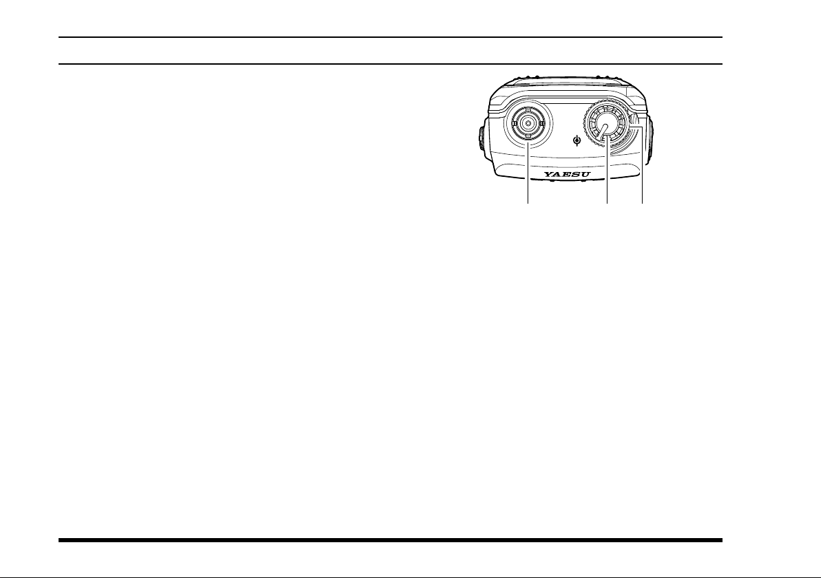
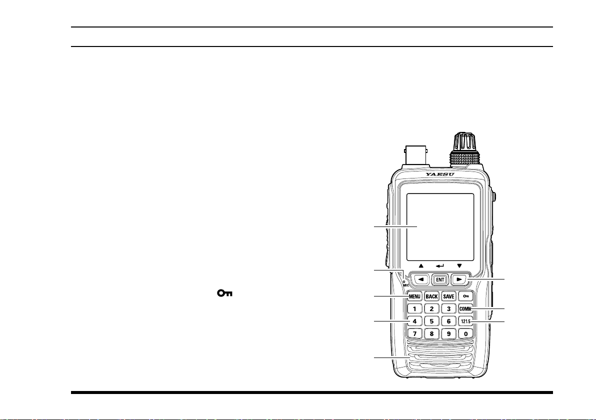
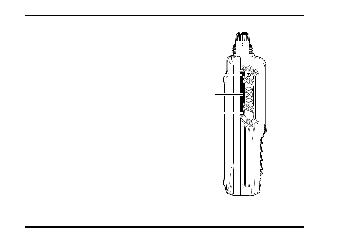
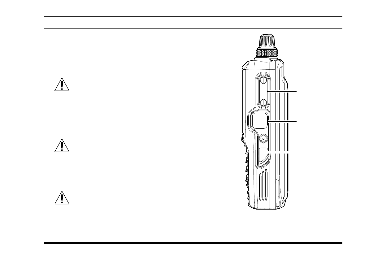
Controls & Connectors ................................................ 4
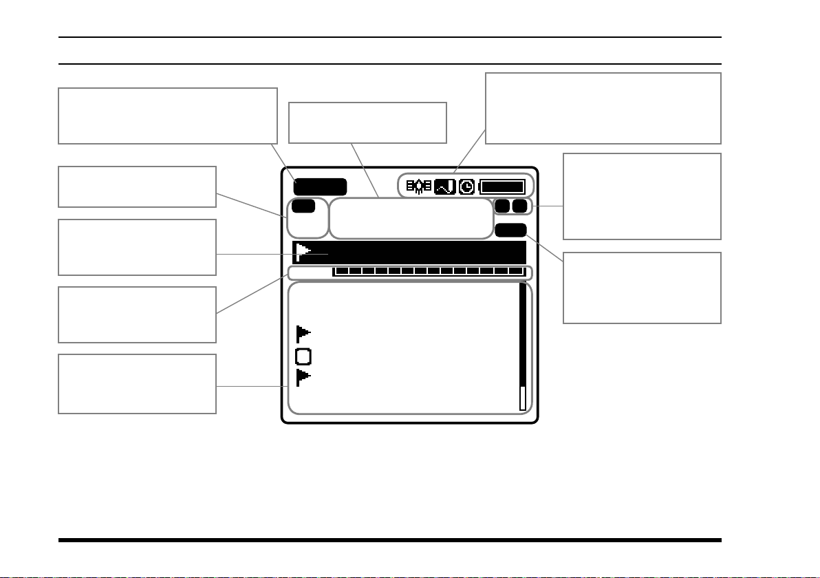
LCD Display .................................................................. 8
Before You Begin........................................................ 12
Battery Installation and Removal .................................... 12
Battery Charging.............................................................. 13
Alkaline Battery Tray Installation ................................... 14
Low Battery Indication.................................................... 14
External DC Power Supply Connection .......................... 15
Antenna Installation......................................................... 15
Belt Clip Installation........................................................ 16
Headset Connection......................................................... 16
Precautions....................................................................... 17
Basic Operation.......................................................... 18
Reception (COM Band)................................................... 18
Accessing the 121.5 MHz Emergency Frequency........... 21
Transmission (COM Band).............................................. 22
Operation Bands .............................................................. 23
Operation Modes ............................................................. 24
Resetting the Radio.......................................................... 25
Advanced Operation .................................................. 27
Reception of VOR Signals............................................... 27
Reception of ILS Signals................................................. 31
Split Operation................................................................. 33
Reception of Weather Channel Broadcasts...................... 35
Dual Watch Operation ..................................................... 37
Timer Mode Operation .................................................... 39
TOT Feature..................................................................... 43
Saving the Battery during Reception............................... 43
Using the Headset Microphone ....................................... 44
VOX Operation................................................................ 44
Side Tone Control ............................................................ 45
Lock Function.................................................................. 46
PTT Lock Function.......................................................... 48
Changing the Channel Steps............................................ 48
ANL Feature .................................................................... 49
Memory Operation...................................................... 50
Recalling the Memories................................................... 50
Instant Storage ................................................................. 52
Maintenance of the Memory............................................ 53
Scanning Operation ................................................... 57
Scanning Channels .......................................................... 57
Selecting Scanning Band ................................................. 58
Scanning the Specied Channels..................................... 59
GPS Function (FTA-750 Only) ................................... 61
Activating the GPS Unit .................................................. 61
Displaying the Position Information................................ 62
Memorizing the Position Information ............................. 64
Recording the Position Information ................................ 65
Waypoint Navigation (FTA-750 Only)........................ 66
Entering the Navigation (NAVI) Mode ........................... 66
Setting the Destination..................................................... 67
Setup Mode ................................................................. 70
Basic Operation ............................................................... 70
Maintenance of the Memory............................................ 71
Setting of the COMM Mode Operation........................... 72
Setting of the GPS Mode Operation (FTA-750 Only)..... 75
Setting of the Operation and Conguration of the Radio 80
About the Radio............................................................... 82
Summary of the SETUP Menu ........................................ 83
Specications ............................................................. 85
Troubleshooting for Headset Connection................ 87

FTA-750/FTA-550 OperATing MAnuAl 1
Important notIce!
FCC RF Exposure Compliance Requirements for Occupational Use Only:
The FTA-750/FTA-550 have been tested and comply with the Federal Communications Commission (FCC) RF expo-
sure limits for Occupational Use/Controlled Exposure Environment. In addition, both radios comply with the following
Standards and Guidelines:
FCC 96-326, Guidelines for Evaluating the Environmental Effects of Radio-Frequency Radiation.
FCC OET Bulletin 65 Edition 97-01 (1997) Supplement C, Evaluating Compliance with FCC Guidelines for Hu-
man Exposure to Radio Frequency Electromagnetic Fields.
ANSI/IEEE C95.1-1992, IEEE Standard for Safety Levels with Respect to Human Exposure to Radio Frequency
Electromagnetic Fields, 3 kHz to 300 GHz.
ANSI/IEEE C95.3-1992, IEEE Recommended Practice for the Measurement of Potentially Hazardous Electromag-
netic Fields - RF and Microwave.
This radio is NOT approved for use by the general population in an uncontrolled environment. This radio is
restricted to occupational use, work related operations only where the radio operator must have the knowl-
edge to control its RF exposure conditions.
When transmitting, hold the radio in a vertical position with its microphone 1 to 2 inches (2.5 to 5 cm) away
from your mouth and keep the antenna at least 1 inch (2.5 cm) away from your head and body.
The radio must be used with a maximum operating duty cycle not exceeding 50%, in typical Push-to-Talk
congurations. DO NOT transmit for more than 50% of total radio use time (50% duty cycle). Transmitting
more than 50% of the time can cause FCC RF exposure compliance requirements to be exceeded.
The radio is transmitting when the “TX”icon is displayed on the upper left corner of the screen of the radio.
You can cause the radio to transmit by pressing the PTT button.
Always use YAESU authorized accessories.
NOTICE
There are no user-serviceable points inside this transceiver.
All service jobs must be referred to your Authorized Service Center.

FTA-750/FTA-550 OperATing MAnuAl
2
IntroductIon
The YAESU FTA-750/FTA-550 are compact, stylish, solid hand-held transceivers providing communication (transmit
and receive) capability on the International Aircraft Communication Band (“COM” band: 118 to 136.975 MHz), and
they additionally provide VOR and ILS navigation features on the “NAV” band (108 to 117.975 MHz).
The FTA-750/FTA-550 boast a 1.7” x 1.7” (43.2 x 43.2 mm) full dot matrix LCD displaying a plenty of information in
a row. The FTA-750/FTA-550 include NOAA weather band monitoring and 200 memory channels. The channel con-
gurations can be easily reprogrammed in minutes using the optional PC Programming Software and your PC. In addi-
tion, the FTA-750 provides positioning and navigation features realized by the internal GPS unit.
We recommend that you read this manual in its entirety, so as to understand the many features of the FTA-750/FTA-
550 completely. Keep this manual handy, so you may use it for reference.
Note: The VOR, ILS, and GPS navigation features of the FTA-750/FTA-550 are for supplemental aids to naviga-
tion only, and are not intended to be a substitute for accurate (primary) VOR or landing service equipment.
You assume full responsibility for the use of the FTA-750/FTA-550.
Congratulations!
You now have at your ngertips a valuable communications tool, a YAESU two-way radio! Rugged, reliable
and easy to use, your YAESU radio will keep you in constant touch with your friends and colleagues for years to
come, with negligible maintenance or down-time.
Please take a few minutes to read this manual carefully. The information presented here will allow you to derive
maximum performance from your radio, in case questions arise later on.
We’re glad you joined the YAESU team. YAESU products cover the entire spectrum of radio communications
applications, and our worldwide support network is here to serve you. Let us help you get your message across.

FTA-750/FTA-550 OperATing MAnuAl 3
models, accessorIes and optIons
Models
FTA-750L Lithium-ion battery pack included
FTA-550L Lithium-ion battery pack included
FTA-550 AA Battery Version
Rechargeable battery pack not includ-
ed. Requires “AA” batteries for opera-
tion.
Supplied Accessories
Lithium-ion Battery Pack (7.4V) SBR-12LI*1
AC Charger SAD-11*1
Charger Cradle SBH-11*1
Cigarette Lighter DC/DC Converter SDD-12
Helical Antenna SRA-13A*2
Belt Clip SHB-11
Headset Adapter Cable SCU-15
Alkaline Battery Tray SBT-12
USB Cable T9101606
Ferrite Core L9190192
Operating Manual
Warranty Card
*1 These accessories are not supplied with the
FTA-550 AA Battery Version.
*2 Antenna gain: 2.15 dBi
Impedance: 50 ohms
Available Options
SSM-10A Speaker Microphone
SEP-10A Earphone (available only with the
SSM-10A)
YCE01 PC Programming Software
(Download the YCE01 PC Program-
ming Software from the YAESU web-
site.)
Availability of accessories may vary. Some accessories
are supplied as standard per local requirements, while
others may be unavailable in some regions. Consult
your YAESU Dealer for details regarding these and any
newly-available options.
Connection of any non-YAESU-approved accessory,
should it cause damage, may void the Limited Warranty
on this apparatus.

FTA-750/FTA-550 OperATing MAnuAl
4
controls & connectors (top panel)
Antenna Jack
This BNC connector accepts the supplied flexible
antenna, or an external antenna designed to provide
50 Ω impedance on the Aircraft Communication
Band.
VOLUME (Inner) Knob
Turn this (inner) control clockwise to increase the
volume.
DIAL Selector (Outer) Knob
This (outer) 20-position detented rotary switch tunes
the operating frequency or selects the memory chan-
nels.
DIAL
VOL

FTA-750/FTA-550 OperATing MAnuAl 5
LCD (Liquid Crystal Display)
The display shows selected operating conditions, as
indicated on Pages 8 to 11.
Microphone
Speak into this opening in a normal voice level,
while pressing the PTT switch, to transmit.
Cursor Keys and ENT Key
The cursor keys [◄]and [►]are used to select an
item displayed on the LCD.
Press the ENT key to determine the selection or
entered values.
Control Keys
Press the MENU key to display the MENU screen.
Press the BACK key to return the display to the
previous screen.
Press the SAVE key to store the current channel
information to the memory.
Press and hold the lock key [] to enable the
lock feature. Controls and keys will be disabled.
Press and hold again to disable the lock feature.
COMM Key
Press this key to enter the COMM mode instantly.
Numeric Keypad
The keypad is used when setting frequencies.
121.5 Key
Press and hold this key to access the emergency
frequency (121.5 MHz) instantly.
Loudspeaker
The internal speaker is located in this position.
controls & connectors (Front panel)

FTA-750/FTA-550 OperATing MAnuAl
6
POWER Switch
Press and hold this button to turn the radio on and
off.
PTT (Push To Talk) Switch
Press and hold this button to transmit when you are
operating in the COM band. Release this button to
return to the “Receive” mode. See Page 22 for de-
tails.
SQL (Squelch) Switch
This button may be pressed to “open” the squelch
manually, allowing you to listen for very weak
signals. Press and hold this button for 2 seconds
to “open” the squelch continuously. Press this but-
ton again to resume normal (quiet) monitoring. See
Page 20 for details.
controls & connectors (leFt sIde)
DATA
MIC/SP
EXT
DC
PTT
SQL

FTA-750/FTA-550 OperATing MAnuAl 7
MIC/SP Jack
You may connect the supplied SCU-15 Headset
Adapter Cable or the optional SSM-10A Speaker/
Microphone to this jack. To use this jack, you must
rst remove the cover from the transceiver body.
Do not allow the FTA-750/FTA-550 to get
wet while the cover over the MIC/SP jack is
removed.
DATA Jack
You may connect the optional USB cable to this
jack. To use this jack, you must rst lift the rubber
cover away from the transceiver body.
Do not allow the FTA-750/FTA-550 to get
wet while the rubber cover is removed.
EXT DC Jack
When an external 9.5- to 10.5-Volt DC power
source is available, you may connect the SDD-12
Cigarette Lighter DC/DC Converter here.
1) Do not allow the FTA-750/FTA-550 to
get wet while the rubber cover is removed.
2) Do not connect any accessory unap-
proved by YAESU to supply DC power.
controls & connectors (rIght sIde)
DATA
MIC/SP
EXT
DC
PTT
SQL

FTA-750/FTA-550 OperATing MAnuAl
8
lcd dIsplay (com Band)
VOL
BUSY
MEM
VDW ±
FLG
MR
G
133.800
132.400
134.800 MIAMI
127.600 MIAMI 2
119.150
124.250 North
129.200
Los Angeles
“BUSY” icon appears during
audio reception, or “TX” during
transmission.
This field displays the icons indicating
various statuses of the transceiver, such
as “GPS on”, “Data Logger on”, “Timer
on”, “Battery full”, etc.
This field displays the
operation modes.
This field displays the
operating frequency.
“MEM” icon appears if
the selected channel is
programmed into the Scan
Memory.
This field displays the
icons indicating various
statuses of functions,
such as “VOX on”, “Split
on”, etc.
This field displays the
tag name of the current
channel.
This field displays the
level of the audio volume
or the squelch.
This field displays the
channels you have
previously used.

FTA-750/FTA-550 OperATing MAnuAl 9
lcd dIsplay (naV Band)
Vor cdI screen
113.600
VOL
SOGKT
150
355°
OBS
000°
NAV VOR
FROM
KLAX-VOR
N
S
EW
33
24
21 15
12
30
3
6
113.600
VOL
355°
OBS
000°
NAV VOR
FROM
KLAX-VOR
N
S
EW
33
24
21 15
12
30
3
6
FTA-750 FTA-550
Compass rose
Course indicator (OBS direction)
Deviation marks
Course deviation needle
OBS (omni bearing selector) value
VOR value
TO/FROM indicator
SOG (speed over ground) value according to the
GPS signal
Ils cdI screen
108.500
VOL
NAV
LOC
GS
KLAX-RWY07R
N
S
EW
33
24
21 15
12
30
3
6
108.500
VOL
NAV
LOC
KLAX-RWY07R
FTA-750 FTA-550
Compass rose
Course (runway) indicator
Deviation marks for localizer
Course deviation needle for localizer
Height deviation indicator for glide slope
Deviation marks for glide slope

FTA-750/FTA-550 OperATing MAnuAl
10
lcd dIsplay (Fta-750 only)
gps InFormatIon screen
133.800
MR
FLG
VOL
LAT/LON
23°
56.890N
123°
56.890W
COG
095°
Oct/25 09:56AM
SOGKT
095 ALTM
0956.8
BUSY
MEM
DATE
KLAX-ATIS
Latitude and longitude values
COG (course over ground) value
Date obtained from the GPS signal
SOG (speed over ground) value
Altitude value
gps compass screen
133.800
VOL
SOGkph
360
Oct/25
09:56AM
COG T
000°
ALTft
10000
BUSY
MR
FLG
KLAX-ATIS
MEM
Compass rose
Course indicator
COG (course over ground) value
SOG (speed over ground) value
Altitude value
Date obtained from the GPS signal

FTA-750/FTA-550 OperATing MAnuAl 11
lcd dIsplay (Fta-750 only)
gps status screen
133.800
VOL
BUSY
FLG
MR
KLAX-ATIS
LAT/LON
23°
56.890N
123°
56.890W
Oct/25 09:56AM
DATE
STATUS
SEARCH
GPS receiver operation status
Radar scope for captured GPS satellites
Date obtained from the GPS signal
Latitude and longitude values
GPS signal strength indicator
WaypoInt naVIgatIon screen
133.800
VOL
SOGkph
360
COG T
000°
DSTkm
10
KLAX
BUSY
KLAX-ATIS
MR
ALL
Compass rose
Course indicator
Destination indicator
Tag name of the destination
DST (distance) value
COG (course over ground) value
SOG (speed over ground) value

FTA-750/FTA-550 OperATing MAnuAl
12
BeFore you BegIn
Battery Installation and Removal
To install the battery, insert the battery pack SBR-
12LI into the battery compartment on the back of
the
transceiver
, press the end of the battery pack
while pressing the battery pack latch on the bot-
tom of the
transceiver
, then lock the pack by sliding
the locking plate beside the latch until the entire
“LOCK” appears
.
Note:
Be sure that the rubber gasket on the SBR-12LI is
not loose when inserting.
To remove the battery, turn the
transceiver
off, slide
the locking plate until the
“UNLOCK” appears
en-
tirely
, lift up the
end of the battery pack by pressing
the battery pack latch, then pull out the battery from
the radio.
PUSH
DATA
MIC/SP
EXT
DC
Battery Pack
Latch
Do not attempt to open any of the recharge-
able Lithium-ion packs, as personal injury
or damage to the Lithium-ion pack could
occur if a cell or cells become accidentally short-
circuited.
Note:
To remove the battery pack after the belt clip SHB-11 is
mounted (see Page 16), lift up the clip before you press
the battery pack latch.

FTA-750/FTA-550 OperATing MAnuAl 13
BeFore you BegIn
side of the transceiver directly. In this case, the
“ ” icon will appear in the top right corner
of the LCD display.
4. If the transceiver is inserted correctly, the RED indi-
cator on the SBH-11 will glow.
A fully-discharged pack will be charged com-
pletely in 4 hours, and then the GREEN indica-
tor on the SBH-11 will glow.
It takes 8 hours for full charge with the SAD-
11 connected to the transceiver directly.
Important Notes:
The
SAD-11 is not designed to power the trans-
ceiver for operation (transmission).
Do not leave the charger connected to the trans-
ceiver for continuous periods in excess of 24 hours.
Long term overcharging can degrade the Lithium-
ion battery pack and signicantly shorten its useful
life.
If using a charger other than the SAD-11, SBH-11,
or if using a battery pack other than the SBR-12LI,
follow the appropriate instructions provided with
the charger/battery. Contact your Dealer if you have
any doubts about the appropriateness of the particu-
lar charger or battery pack you intend to use.
Battery Charging
It is necessary to charge the Lithium-ion battery fully
before its rst use. Follow the procedure below:
1.
Install the Lithium-ion battery pack onto the trans-
ceiver. Ensure that the transceiver is switched off.
2. Insert the cable plug of the SAD-11 Battery Char-
ger into the jack located on the back of the SBH-11
Charging Cradle, then plug the SAD-11 into the AC
line outlet.
EXT
DC
MIC/SP
DATA
VOL
DIAL
SBH-11
SAD-11
3. Insert the transceiver into the SBH-11; the antenna
jack should be at the left side when viewing the
cradle from the front.
You may insert the cable plug of the SAD-
11 into the EXT DC jack located on the right

FTA-750/FTA-550 OperATing MAnuAl
14
Alkaline Battery Tray Installation
The
supplied
SBT-12 Battery Tray allows operation of
the FTA-750/FTA-550 using six “AA” size alkaline
battery cells.
When installing a cell, insert the (–) end rst, then
press in the (+) end so the cell snaps into place. Pay
attention to the polarity indicated inside the case.
SBT-12
Alkaline Battery Tray
The SBT-12 must not be used with re-
chargeable cells. The SBT-12 does not con-
tain the thermal and over-current protec-
tion circuits required when utilizing Ni-Cd and Ni-
MH cells.
Note: Replace all six cells at the same time in case of
low battery.
To install the SBT-12, remove the Lithium-ion bat-
tery pack first from the transceiver, turn the open
side of the SBT-12 down, then insert it into the bat-
tery compartment.
Note: Be sure that the rubber gasket on the SBT-12
is not loose when inserting.
Low Battery Indication
As your battery discharges during use, the voltage will
gradually become lower. When the battery voltage
reaches 6.0 Volts, the “ ” icon will blink on the
LCD display, indicating that the battery pack must be
recharged or the alkaline battery cells must be replaced
before further use.
Avoid recharging Lithium-ion batteries before the
“Low Battery” indicator is observed, as this can
degrade the charge capacity of your Lithium-ion
battery pack. YAESU recommends that you carry an
extra, fully-charged pack with you so you will not
lose communications capability due to a depleted
Lithium-ion battery.
The fully-charged battery lasts for 12 hours on the
FTA-750 or 13.5 hours on the FTA-550 under the
conditions below:
Battery saver ... OFF
Operation ratio ... TX:RX:Standby = 6:6:48 (sec)
BeFore you BegIn

FTA-750/FTA-550 OperATing MAnuAl 15
External DC Power Supply Connection
You may insert the cable plug of the optional SDD-12
Cigarette Lighter DC/DC Converter into the EXT DC
jack located on the right side of the transceiver. In this
case, the “ ” icon will appear in the top right corner
of the LCD display.
When making DC connections via the SDD-12, be ab-
solutely certain to observe the proper voltage level and
polarity guidelines.
The SDD-12 can be connected to 12 to 24 Volt DC
power sources.
SDD-12
Cigarette Lighter DC/DC
Converter (12 to 24 Volts)
Ferrite Core
Wind the cable one turn,
then snap two halves
As close
as possible
For noise reduction from exogenous noise, wind one
turn of the SDD-12 cable around the ferrite core,
and snap its two halves together, per the illustration
above. Attach the ferrite core as close as possible to
the SDD-12 body, as shown.
Do not connect any accessory unapproved
by YAESU to supply DC power; otherwise
the FTA-750/FTA-550 may be damaged.
Antenna Installation
To attach the supplied antenna to the FTA-750/
FTA-550, grasp the base of the antenna rmly, and
exert a moderate “pinching” pressure on the base
as you press the antenna onto the radio’s antenna
connector. While exerting this pressure, rotate the
antenna clockwise 1/4 turn to lock the antenna in
place.
BeFore you BegIn

FTA-750/FTA-550 OperATing MAnuAl
16
BeFore you BegIn
Belt Clip Installation
You may mount the clip to the rear of the FTA-750/
FTA-550 using the supplied screws.
DATA
MIC/SP
EXT
DC
DATA
MIC/SP
EXT
DC
SHB-11
Belt Clip
with two screws (M3 x 8)
Headset Connection
You may use an optional headset through the supplied
SCU-15 Headset Adapter Cable (see also Page 87).
Headset
(not supplied)
SCU-15
Headset Adapter Cable
1. Remove the cover and two screws of the MIC/SP
jack located on the right side of the transceiver.
2. Insert the plug of the SCU-15 to the MIC/SP jack.
3. Fix the plug with two screws attached to the SCU-
15.
Either of the plug directions are acceptable as
long as the both screws t the screw holes.
4. Insert the plugs of the headset to the sockets of the
SCU-15.

FTA-750/FTA-550 OperATing MAnuAl 17
BeFore you BegIn
Precautions
The
FTA-750/FTA-550 are capable of two-way
communication on channels used for critical avia-
tion safety communications. Therefore, it is impor-
tant that this radio be kept away from children or
other unauthorized users at all times.
Do not dispose of the Lithium-ion battery pack in a
re. Do not carry a Lithium-ion battery pack in your
pocket, where keys or coins could short the termi-
nals. This could create a serious fire/burn danger,
and possibly cause damage to the Lithium-ion pack.
The
FTA-750/FTA-550 are designed to have the
waterproof capability equivalent to IPX5. Do not
allow the radio to become submerged, and do not
subject it to water spray under pressure.

FTA-750/FTA-550 OperATing MAnuAl
18
BasIc operatIon
Reception (COM Band)
Turning the radio on and off
To turn the radio on,
press and hold the
POWER switch.
“WARNING” will be
displayed.
PTT
SQL
This device can only
be used as an aid to
navigation for VFR.
All information
is presented for
reference only.
You assume total
responsibility and
risk associated with
using this device.
WARNING
I agree
If you agree with the
warning message, press
the [ENT] key.
A channel frequency will
appear on the display. If
not, press the [COMM]
key.
The “
BUSY
” icon appears on the display when the
audio signal is received on the current frequency.
127.300
VOL
BUSY
To turn the radio off, press and hold the POWER
switch.
Other manuals for FTA-750 Spirit
2
This manual suits for next models
3
Table of contents
Other Yaesu Transceiver manuals

Yaesu
Yaesu FT DX 3000 User manual

Yaesu
Yaesu FT-2500M Manual

Yaesu
Yaesu FT-857 series Manual

Yaesu
Yaesu FT-101ZD User manual

Yaesu
Yaesu FT-767GX User manual

Yaesu
Yaesu VX-127 User manual

Yaesu
Yaesu FT-710 User manual

Yaesu
Yaesu FT-101ZD User manual

Yaesu
Yaesu Mark-V FT-1000MP Manual

Yaesu
Yaesu FT-736R User manual