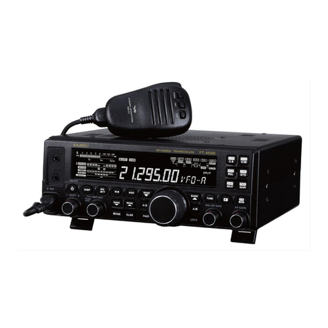
Yaesu FT-710 User manual

HF/50 MHz TRANSCEIVER
FT-710
Introduction
This manual provides the technical information necessary
for servicing the FT-710 HF/50 MHz TRANSCEIVER.
Servicing this equipment requires expertise in handling
surface-mount chip components. Attempts by non-qualied
persons to service this equipment may result in permanent
damage not covered by the warranty, and may be illegal in
some countries.
While we believe the information in this manual to be cor-
rect, YAESU assumes no liability for damage that may oc-
cur as a result of typographical or other errors that may be
present. Your cooperation in pointing out any inconsisten-
cies in the technical information would be appreciated.
Important Note
This transceiver was assembled using Pb (lead) free solder, based on the RoHS specication.
Only lead-free solder (Alloy Composition: Sn-3.0Ag-0.5Cu) should be used for repairs performed on this apparatus. The solder stated
above utilizes the alloy composition required for compliance with the lead-free specication, and any solder with the above alloy com-
position may be used.
Technical Supplement
EH080H90A
©2022 YAESU MUSEN CO., LTD.
Contents
Specications
Exploded View
Block Diagram
Connection Diagram
Alignment
Board Unit (Schematics, Layouts & Parts)
MAIN Unit
PA Unit
DISPLAY Unit
JACK Unit

FT-710 Technical SupplementSPESIFICATIONS -1
Specications
General
Tx Frequency Ranges: 1.8MHz - 54MHz (Amateur bands only)
70MHz - 70.5MHz (UK Amateur bands only)
Rx Frequency Range: 30kHz - 75MHz (operating)
1.8MHz-29.699999MHz(speciedperformance,Amateurbandsonly)
50MHz-53.999999MHz(speciedperformance,Amateurbandsonly)
70MHz - 70.499999MHz(speciedperformance,UKAmateurbandsonly)
Emission Modes: A1A(CW),A3E(AM),J3E(LSB,USB),F3E(FM)
Frequency Steps: 1*/5/10/20Hz(CW,SSB,AM),100Hz(FM)*FINEtuning“ON”
Antenna Impedance: 50Ohms,unbalanced(AntennaTunerOFF)
16.7-150Ohms,unbalanced
(AntennaTunerON,1.8MHz-29.7MHzAmateur bands)
25-100Ohms,unbalanced(Antenna TunerON,50MHzAmateur band)
Operating Temperature Range: +32°Fto+122°F(0°Cto+50°C)
Frequency Stability: ±0.5ppm(after1minute@+32°Fto+122°F[0°Cto+50°C])
Supply Voltage: DC13.8V±15%(NegativeGround)
Power Consumption (Approx.): Rx (no signal) 1.8A
Rx (signal present) 2.2A
Tx (100W) 21A
Dimensions(WxHxD): 9.4”x3.1”x9.7”(239x80x247mm)
Weight (Approx.): 9.92lbs (4.5kg)
Transmier
Power Output: 5-100was(5-25WAMcarrier)
Modulation Types: J3E(SSB):Balanced,
A3E(AM):Low-Level(EarlyStage),
F3E(FM):VariableReactance
Maximum FM Deviation: ±5.0kHz/±2.5kHz(Narrow)
Harmonic Radiation: Beerthan–50dB(1.8MHz-29.7MHzAmateurbands)
Beerthan–63dB(50MHz Amateur band)
SSB Carrier Suppression: Atleast60dBbelowpeakoutput
Undesired Sideband Suppression:Atleast60dBbelowpeakoutput
Bandwidth: 3kHz(LSB/USB),500Hz(CW),6kHz(AM),16kHz(FM)
Audio Response(SSB): Notmorethan–6dBfrom300to2700Hz
Microphone Impedance: 600Ohms(200to10kOhms)

FT-710 Technical SupplementSPESIFICATIONS -2
Specications
Receiver
Circuit Type: DirectSamplingSuperheterodyne
Intermediate Frequencies: SSB,CW:18kHz/AM,FM:24kHz
Sensitivity: SSB,CW(BW:2.4kHz,10dBS+N/N)
1.8MHz-30MHz 0.16µV(IPO:AMP2)
50MHz - 54MHz 0.125µV (IPO:AMP2)
70MHz - 70.5MHz 0.16µV (IPO:AMP2)
AM(BW:6kHz,10dBS+N/N,30%modulation@400Hz)
0.5MHz - 1.8MHz 6.3µV
1.8MHz - 30MHz 2µV (IPO:AMP2)
50MHz - 54MHz 1µV (IPO:AMP2)
70MHz - 70.5MHz 2µV (IPO:AMP2)
FM(BW:12kHz,12dBSINAD,3.5kHzDEV@1kHz)
28 - 30MHz 0.25µV (IPO:AMP2)
50MHz - 54MHz 0.2µV (IPO:AMP2)
70MHz - 70.5MHz 0.25µV (IPO:AMP2)
Selectivity(typ): Mode –6dB –60dB
CW(BW:0.5kHz) 0.5kHzorbeer 750Hzorless
SSB(BW:2.4kHz) 2.4kHzorbeer 3.6kHzorless
AM(BW:6kHz) 6kHzorbeer 15kHzorless
FM(BW:12kHz) 12kHzorbeer 25kHzorless
Image Rejection: 70dBorbeer(1.8MHz-28MHzAmateurbands)
60dBorbeer(50MHzAmateurband)
Maximum Audio Output: 2.5Winto4Ohmswith10%THD
Audio Output Impedance: 4to16Ohms(4Ohms:nominal)
Conducted Radiation: Lessthan4nW
Specications are subject to change, in the interest of technical improvement, without notice or obligation,
and are guaranteed only within the amateur bands.

EXPLODED VIEW -1 FT-710 Technical Supplement
Exploded View
*Accessory with RA6422300 KNOB MAIN ASSY
REF. YAESU P/N Description Qty.
U9900328 RAMIMAIT TAPTITE-B M2.6X6B 2
U24105001 BIND HEAD TAPTITE-B M2X5(3) 2
U24208007 BIND HEAD TAPTITE-B M2.6X8B 9
U24205001 BIND HEAD TAPTITE-B M2.6X5 6
U34308001 FLAT HEAD TAPTITE-B M3X8 4
Non-designated parts are available only as part of a designated assembly.
RA640290A
FRONT PANEL(PRT)
R7155600 (4 pcs)
HIMERON
U70015001
PLAIN WASHER FW9X14X0.5
U62009001
VOLUME NUT 9X12X2
RA6403600
LEVER
U9900211
WAVE WASHER WW-16011(SUS)
RA6074800
HOLDER (SPRING)
RA6358900
RUBBER RING (MAIN)
RA6422300
KNOB MAIN ASSY
RA1528400
WASHER (PE)
RA152820A
WASHER (FELT)
RA6400000
VOLUME KNOB
RA6400100
ENCODER KNOB (MULTI)
RA6400200
ENCODER KNOB (SUB)
RA6402000
RUBBER KNOB (TOP)
RA6400700
HOLDER RUBBER
RA6403100
LIGHT GUIDE (PWR)
RA6403200
LIGHT GUIDE (VOX)
RA6403500
LIGHT GUIDE (MCH)
RA6403300
LIGHT GUIDE (MAIN)
RA6403300
LIGHT GUIDE (MAIN)
RA6403400
LIGHT GUIDE (TX)
RA6402100
RUBBER KNOB (PWR)
RA6402200
RUBBER KNOB (MAIN)
RA6402400
RUBBER KNOB (R)
RA640230A
RUBBER KNOB (L)
RA6405100 (6 pcs)
LCD SPACER (B)
RA6400800 (3 pcs)
PANEL FRAME
RA6419100
PORON SHEET (D9)
RA6419000
PORON SHEET (D6)
RA1145500
CAPTON TAPE (15X10)
RA6419000
PORON SHEET (D6)
RA6400800
PANEL FRAME
Q7001001
LCD MODULE
RA6405000
LCD SPACER (A)
RA6035100
LEAF SPRING
RA6419200
PORON SHEET (101012)
T9207942
WIRE ASSY:AH068H-40MM6P
RA6358300
DOUBLE FACE TAPE
RA6434100
SHIELD CASE (DISP)
Q9001000
ROTARY ENCODER REL20-50LD
DISPLAY-UNIT L9190239
FERRITE CORE:FPCR17-9-0.5
T9207660
WIRE ASSY AH046H 110MM30P
T9207491A
WIRE ASSY AH036H 110MM24P
CS2716701
JACK-ASSY
CS2715701
DISPLAY-ASSY

EXPLODED VIEW -2 FT-710 Technical Supplement
Exploded View
REF. YAESU P/N Description Qty.
U9900369 OVAL HEAD SCREW:M3X6B(ALOCK) 18
U24206001 BIND HEAD TAPTITE-B M2.6X6 38
U9900272 PAN HEAD TAPTITE-B HM3X8(3) 3
U02310001 OVAL HEAD SCREW:M3X6B(ALOCK) 4
U24208007 BIND HEAD TAPTITE-B M2.6X8B 3
U24308001 BIND HEAD TAPTITE-B M3X8 2
U04410002 SEMS SCREW HSM4X10NI 1
U04333007 SEMS SCREW HSM3X33B 4
U03106001 SEMS SCREW ASM2X6 4
U20406007 BINDING HEAD SCREW M4X6B 2
Non-designated parts are available only as part of a designated assembly.
RA6401300
TOP CASE
RA6401000
SHIELD PLATE (PA)
RA6445900
PORON SHEET(10104)
RA6311500
SPONGE RUBBER (SP)
RA6405400
BLIND SHEET (SP2)
RA6396000
CHASSIS
RA602540A
PORON SHEET (10x115)
T9207971A
WIRE ASSY
S5000320A
FAN GUARD G60-4
M4090264
SPEAKER
M2090073
FAN
RA6443100 (4 pcs)
LEG
RA6400900
SP HOLDER
P1091158C
CONNECTOR
RA6405200
DISPLAY PANEL
RA089840A
SP NET
RA602540A
PORON SHEET (10x115)
RA6334300
ThermalConductivePad
PA-UNIT
RA6405300
BLIND SHEET (SP)
RA6419300
SPONGE RUBBER
PA-UNIT
Connect to J1002 on the MAIN-Unit
T9207491A
WIRE ASSY
T9207926
WIRE ASSY
Connect to J1001 on the MAIN-Unit
T92079970
WIRE ASSY
Connect to J1005 on the MAIN-Unit
T9207840
WIRE ASSY
Connect to J3001 on the MAIN-Unit
Connect to J3004 on the MAIN-Unit
Connect to J2607 on the MAIN-Unit
RA6401200
BOTTOM CASE
R3100700B
FOOT
S4000061
SNAP-IN PLA FOOT:TP-4
R0145630
STAND
RA6443100
LEG
RA6443100
LEG
RA6443100
LEG
RA6119900
GASKET (6x6x12)
RA6468600
GASKET (2530)
RA6443100
LEG
RA6035100
LEAF SPRING
RA6143800
GASKET (5X10)
RA6334500
ThermalConductivePad
RA6334400
ThermalConductivePad
TT9207967
WIRE ASSY
RA6119900
GASKET (6x6x12)
RA6445600
GASKET (103010)
RA6452000
GASKET (101010)
L9190238
FERRITE PLATE:FT111-08
RA0459300
SHIELD SHEET
RA6405500
GASKET (USB)
TT9207972
WIRE ASSY
Connect to J7002 on the JACK-Unit
CS2712704 DST: USA
CS2712705 DST: EU
MAIN-ASSY
CQ1350001
BOTTOM-CASE-ASSY
CQ1349001
TOP-CASE-ASSY
CS2714701 DST: USA
CS2714702 DST: EU
PA-ASSY

BLOCK DIAGRAM -1 FT-710 Technical Supplement
Block Diagram

CONNECTION DIAGRAM -1 FT-710 Technical Supplement
Connection Diagram

Alignment
FT-710 Technical SupplementALIGNMENT -1
Introduction and Precautions
RealignmentmAyberequiredafterthecomponents
havebeenreplaced.
WerecommendthatauthorizedYaesuTechnicians,
whoareexperiencedwiththecircuitryandfully
equippedtoalignourproducts,performaligns.
Thosewhodoundertakeanyofthefollowing
alignmentsarecautionedto proceed at theirown
risk.Problemscausedbyunauthorizedaemptsat
realignmentarenotcoveredbythewarrantypoli-
cy.
Theneedforrealignmentshouldbedeterminedto
be absolutely necessary.
Thefollowing test equipment (and a thorough fa-
miliaritywithitscorrectuse)isnecessaryforcor-
rectrealignment. Most steps do not require allof
theequipmentlisted.Theinteractionsofsomead-
justmentsmAyrequirethatmorecomplex adjust-
mentsbeperformedinasequence.Donotaempt
toperformonlyasinglestepunlessitisclearlyiso-
latedelectricallyfromallothersteps.Havealltest
equipmentreadybeforebeginning, and follow all
ofthestepsinasectionintheordertheyarepre-
sented.
Required Test Equipment
RFSignalGenerator
AFSignalGenerator
SpectrumAnalyzergoodtoatleast1GHz.
FrequencyCounter
SINADMeter
RFMillivoltmeter
DC Voltmeter
DC Ammeter (30A)
16-OhmDummyLoad(100was)
50-OhmDummyLoad(100was)
100-OhmDummyLoad(200was)
150-OhmDummyLoad(100was)
In-LineWameter(150was,50-Ohm)
4-OhmAFDummyLoad(3was)
1/4-inch3-contactPlug
Important Notice
Donotadjustthealignmentmenusthatarenot
mentionedinthismAnual.
Alignment Preparation & Precautions
A50-ohm RF Dummyload and in-line wameter
mustbeconnectedtothe“ANT”jackinallproce-
duresthatcallfortransmission,exceptwherespec-
ifiedotherwise. Correctalignmentisnotpossible
withanantenna.
Aftercompletingonestep,readthefollowingstep
todeterminewhetherthesametestequipment
willberequired.Ifnot,removetheunneededtest
equipmentbeforeproceeding.(exceptthedummy
loadandwameter).
Correctalignmentrequiresthattheambienttem-
peraturebemAintainedconstantbetween68°Fto
86°F(20°Cto30°C).Whenthetransceiveris
broughtintotheshopfromahotorcoldenviron-
ment,itshouldbeallowedtimeto come to room
temperaturebeforealignment.Also,thetestequip-
mentmustbethoroughlywarmedupbeforebegin-
ning.
Wheneverpossible,alignmentsshouldbemAde
withoscillatorshieldsandcircuitboardsrmlyaf-
xedinplace.
Note:Signal levelsin dB referredto in thisproce-
durearebasedon0dBµV=0.5µV(closedcir-
cuit).

Alignment
FT-710 Technical SupplementALIGNMENT -2
REF OSC Adjustment
ConnectthefrequencycountertoTP1005on
themAINUnit.
Pressandholdinthe[BAND],[QMB]and
[NAR]keys,whileturningtheradioON,toen-
terthealignmentmode.
Rotatethe[FUNC]knobtoselectthealignment
parameter“003[GN]REFFREQ”.
Rotatethe[STEP/MCH(DSP)]knobsothat
thefrequencycounterreadingis“250.000000
±20Hz”.
Pressandholdthe[FUNC]knobtosavethe
newseing.
TP1005

Alignment
FT-710 Technical SupplementALIGNMENT -3
RF AGC Adjustment
Pressandholdinthe[BAND],[QMB]and
[NAR]keys,whileturningtheradioON,toen-
terthealignmentmode.
1. Rotatethe[FUNC]knob to select the align-
mentparameter“023[RX]RF-AGC7”.
2. Rotatethe [STEP/MCH (DSP)] knob so that
theparameterindication“255”.
PerformthesameproceduresfortheAlignment
parameter“024[RX]RF-AGC14”through“027
[RX]RF-AGC50”.
IF AGC Adjustment
ConnecttheAFmillivoltmeterand4Ohm
dummyloadtotheEXTSPKRjack.
ConnecttheRFSignalGeneratortotheANT
jack,thensettheoutputlevelto40dBµV.
Adjustthe[AFGAIN]knobsothattheAFmil-
livoltmeterreadingis“0dB”.
SettheRFSignalGeneratoroutputlevelto
10dBµV.
Pressandholdinthe[BAND],[QMB]and
[NAR]keys,whileturningtheradioON,toen-
terthealignmentmode.
Selecttheappropriate“AlignmentParameter”
usingthe[FUNC]knobperthechartbelow,
thensettheRFSignalGeneratoroutputtoeach
frequency& level,andadjust the [STEP/MCH
(DSP)]knobforthecorrespondingAFmillivolt-
meterreadingateachfrequency.
Alignment
Parameter
RF Signal
Generator Frequency AF
Millivoltmeter
028 [RX] IF-AGC 7 7.150MHz
10dBµV 7.150MHz
-2.0dB ± 0.5dB
029 [RX] IF-AGC 14 14.200MHz
10dBµV 14.200MHz
030 [RX] IF-AGC 21 21.200MHz
10dBµV 21.200MHz
031 [RX] IF-AGC 28 28.100MHz
10dBµV 28.100MHz
032 [RX] IF-AGC 50 50.500MHz
10dBµV 50.500MHz
Pressandholdinthe[FUNC]knobtosavethe
newseing.
S-meter Adjustment
Setthefollowingcontrolsasindicated:
[IPO]:AMP1
[ATT]:OFF
[WIDTH]:2.4kHz
ConnecttheRFSignalGeneratortotheANT
jack,thensetthefrequencyto14.200MHz.
Pressandholdinthe[BAND],[QMB]and
[NAR]keys,whileturningtheradioON,toen-
terthealignmentmode.
Selecttheappropriate“AlignmentParame-
ter”usingthe[FUNC]knobperthechartbelow,
thensettheRFSignalGeneratoroutputtoeach
frequency& level,andadjust the [STEP/MCH
(DSP)]knobforthecorrespondingS-meter
readingateachfrequency.
Alignment Parameter RF Signal Generator S-meter
033 [RX] S-MTR 0 OFF Parameter “0”
034 [RX] S-MTR 2 +16dBµV S2
035 [RX] S-MTR 5 +24dBµV S5
036 [RX] S-MTR 7 +30dBµV S7
037 [RX] S-MTR 9 +36dBµV S9
038 [RX] S-MTR +10 +46dBµV S9+10
039 [RX] S-MTR +20 +56dBµV S9+20
040 [RX] S-MTR +30 +66dBµV S9+30
041 [RX] S-MTR +40 +76dBµV S9+40
042 [RX] S-MTR +50 +86dBµV S9+50
043 [RX] S-MTR +60 +96dBµV S9+60
Pressandholdinthe[FUNC]knobtosavethe
newseing.
Alignment
FT-710 Technical SupplementALIGNMENT -4
FM Squelch Adjustment
Setthefollowingcontrolsasindicated:
[IPO]:AMP1
[ATT]:OFF
[R.FLT]:12kHz
SettheRFSignalGeneratorto-8dBµVatthe
51.500MHzofa1kHz±3.5kHzdeviationFM
modulation audio signal.
Pressandholdinthe[BAND],[QMB]and
[NAR]keys,whileturningtheradioON,toen-
terthealignmentmode.
Rotatethe[FUNC]knobtoselectthealignment
parameter“046[RX]FMSQLTHW”.
Pressthe[STEP/MCH(DSP)]knob.
SettheRFSignalGeneratorto-8dBµVatthe
51.500MHzofa1kHz±1.75kHz deviationFM
modulation audio signal.
Rotatethe[FUNC]knobtoselectthealignment
parameter“047[RX]FMSQLTHN”.
Pressthe[STEP/MCH(DSP)]knob.
SettheRFSignalGeneratorto0dBµVatthe
51.500MHzofa1kHz±3.5kHzdeviationFM
modulation audio signal.
Rotatethe[FUNC]knobtoselectthealignment
parameter“048[RX]FMSQLTI”.
Pressthe[STEP/MCH(DSP)]knob.
Pressandholdinthe[FUNC]knobtosavethe
newseing.

Alignment
FT-710 Technical SupplementALIGNMENT -5
PA Unit Adjustment
Preparation
Connectthe 50-OhmDummyLoadand Watt-
metertotheANTjack.
DisconnectthecoaxialcablesfromJ4001onthe
PAUnit,then terminateJ4001witha50-Ohm
resistor.
DisconnectthejumperplugsfromJ4004and
J4005onthePAUnit.
Pre-Drive Stage Idling Current Adjustment
ConnecttheDCammetertoJ4004onthePAUnit.
Rotatethe[FUNC]knobtoselectthealignment
parameter“050[TX]MFPREDR-BIAS”.
Pressand hold the PTT switch then adjust the
[STEP/MCH(DSP)]knobsothattheDCamme-
terreadingis“100mA(±10mA)”.
ReleasethePTTswitch.
Rotatethe[FUNC]knobtoselectthealignment
parameter“053[TX]HFPREDR-BIAS”.
Pressand hold the PTT switch then adjust the
[STEP/MCH(DSP)]knobsothattheDCamme-
terreadingis“100mA(±10mA)”.
ReleasethePTTswitch.
Rotatethe[FUNC]knobtoselectthealignment
parameter“056[TX]VHFPREDR-BIAS”.
Pressand hold the PTT switch then adjust the
[STEP/MCH(DSP)]knobsothattheDCamme-
terreadingis“100mA(±10mA)”.
ReleasethePTTswitch.
J4001 J4004 J4005

Alignment
FT-710 Technical SupplementALIGNMENT -6
Drive Stage Idling Current Adjustment
ConnecttheDCammetertoJ4005onthePAUnit.
Rotatethe[FUNC]knobtoselectthealignment
parameter“051[TX]MFDRIVE-BIAS”.
Pressand hold the PTT switch then adjust the
[STEP/MCH(DSP)]knobsothattheDCamme-
terreadingis“500mA(±50mA)”.
ReleasethePTTswitch.
Rotatethe[FUNC]knobtoselectthealignment
parameter“054[TX]HFDRIVE-BIAS”.
Pressand hold the PTT switch then adjust the
[STEP/MCH(DSP)]knobsothattheDCamme-
terreadingis“500mA(±50mA)”.
ReleasethePTTswitch.
Rotatethe[FUNC]knobtoselectthealignment
parameter“057[TX]VHFDRIVE-BIAS”.
Pressand hold the PTT switch then adjust the
[STEP/MCH(DSP)]knobsothattheDCamme-
terreadingis“500mA(±50mA)”.
ReleasethePTTswitch.
Final Stage Idling Current Adjustment
ConnecttheDCammeterbetweenExternal
Powersupplyandthetransceiver.
Rotatethe[FUNC]knobtoselectthealignment
parameter“052[TX]MFFINAL-BIAS”.
Pressand hold the PTT switch then adjust the
[STEP/MCH(DSP)]knobsothattheDCamme-
terreadingis“1.0A(±100mA)”.
ReleasethePTTswitch.
Rotatethe[FUNC]knobtoselectthealignment
parameter“055[TX]HFFINAL-BIAS”.
Pressand hold the PTT switch then adjust the
[STEP/MCH(DSP)]knobsothattheDCamme-
terreadingis“1.5A(±150mA)”.
ReleasethePTTswitch.
Rotatethe[FUNC]knobtoselectthealignment
parameter“058[TX]VHFFINAL-BIAS”.
Pressand hold the PTT switch then adjust the
[STEP/MCH(DSP)]knobsothattheDCam-
meterreadingis“1.5A(±150mA)”(European
Version:“1.0A(±150mA)”).
ReleasethePTTswitch.
Pressandholdinthe[FUNC]knobtosavethe
newseing.
Termination
TurnOFFthetransceiver.
Disconnectthe50-OhmresistorsfromJ4001,
thenconnectthecoaxialcablestoJ4001.
Re-connectthejumperplugstoJ4004andJ4005.
Current ALC Adjustment
Connectthe 50-OhmDummyLoadand Watt-
metertotheANTjack.
Settheoperatingmodeto“CW-U”.
Pressandholdinthe[BAND],[QMB]and
[NAR]keys,whileturningtheradioON,toen-
terthealignmentmode.
1. Rotatethe[FUNC]knob to select the align-
mentparameter“059[TX]I-ALC1.8”forthe
1.8MHzamateurband'sALCAdjustment.
2. Keythetransmitter,thenadjustingthe
[STEP/MCH(DSP)]knobfor110Wonthe
Wameter.
3. Unkeythetransmier.
PerformthesameproceduresfortheAlignment
parameter“060[TX]I-ALC3.5”through“068
[TX]I-ALC50”.
UK version only
Rotatethe[FUNC]knobtoselectthealign-
mentparameter“069[TX]I-ALC70”forthe
70MHzamateurband'sALCAdjustment.
Keythetransmitter,thenadjustingthe
[STEP/MCH(DSP)]knobfor60Wonthe
Wameter.
Unkeythetransmier.
Pressandholdinthe[FUNC]knobtosavethe
newseing.

Alignment
FT-710 Technical SupplementALIGNMENT -7
ALC Meter Adjustment
Connectthe 50-OhmDummyLoadand Watt-
meter to theANTjack.
Setthefollowingcontrolsasindicated:
MICGAIN:50
AMC: 100
Pressandholdinthe[BAND],[QMB]and
[NAR]keys,whileturningtheradioON,toen-
terthealignmentmode.
Rotatethe[FUNC]knobtoselectthealignment
parameter“130[TX]100WFALC14”.
Keythetransmier,thenrotatethe[STEP/MCH
(DSP)]knobfor100W(+5W/–0W)ontheWa-
meter.
Unkeythetransmier.
Rotatethe[FUNC]knobtoselectthealignment
parameter“246[TX]ALCMTR”.
ConnecttheAudioGeneratortopin5ofthe
MICjack(pin4:GND). MIC GNDMIC SettheAudioGeneratorto20mVrms@1kHz.
PressandholdthePTTswitch,thenadjustthe
AudioGeneratoroutputlevelfor90W-95Won
theWameter.
ReleasethePTTswitch.
IncreasetheAudioGeneratoroutputlevelby
“9dB”.
PressthePTTswitch,thenpressthe[STEP/
MCH(DSP)] knob while pressing and holding
in the PTT switch.
ReleasethePTTswitch.
Pressandholdinthe[FUNC]knobtosavethe
newseing.
TX Output Power Adjustment
PO Meter Adjustment
TXG Adjustment
Connectthe 50-OhmDummyLoadand Watt-
metertotheANTjack.
Pressandholdinthe[BAND],[QMB]and
[NAR]keys,whileturningtheradioON,toen-
terthealignmentmode.
1. Rotatethe[FUNC]knobtoselectthealign-
mentparameter“072[TX]100WTXG1.8”.
2. Rotatethe[STEP/MCH(DSP)]knobsothat
theparameterindication“200”.
3. Rotatethe[FUNC]knobtoselectthealign-
mentparameter“070[TX]100WFALC1.8”.
4. Pressand hold the PTT switch, then rotate
the[STEP/MCH(DSP)]knobfor101W
(+5W/–1W)ontheWameter.
5. ReleasethePTTswitch.
6. Rotatethe[FUNC]knobtoselectthealign-
mentparameter“071[TX]100WMTR1.8”.
7.
PressandholdthePTTswitch,thenpressthe
[STEP/MCH(DSP)]knob
.
8. ReleasethePTTswitch.
9. Rotatethe[FUNC]knobtoselectthealign-
mentparameter“072[TX]100WTXG1.8”.
10.Press and holdthe PTT switch, then rotate
the[STEP/MCH(DSP)]knobformaximum
deectionontheALCmeterzone.
11.ReleasethePTTswitch.
PerformthesameproceduresfortheAlignment
parameter“073[TX]50WFALC1.8”through
“084[TX]5WTXG1.8”asindicatedbythe
chartonthenextpage.
PerformthesameproceduresfortheAlignment
parameter“085[TX]100WFALC3.5”through
“219[TX]5WTXG50”(UKversion:“234[TX]
5WTXG70”)as indicated by the chartonthe
next page.
Pressandholdinthe[FUNC]knobtosavethe
newseing.
Alignment
FT-710 Technical SupplementALIGNMENT -8
Alignment
parameter Operation POWER meter
(Adjust to)
ALC Meter Zone
(Adjust to)
1.8MHz
070
Rotate the
[STEP/MCH
(DSP)] knob
101W (+5W/-1W) -
072 - Maximum deection
073 50W (+5W/-0W) -
075 - Maximum deection
076 20W (+2W/-0W) -
078 - Maximum deection
079 10W (+1W/-0W) -
081 - Maximum deection
082 5W (+1W/-0W) -
084 - Maximum deection
3.5MHz
085
Rotate the
[STEP/MCH
(DSP)] knob
101W (+5W/-1W) -
087 - Maximum deection
088 50W (+5W/-0W) -
090 - Maximum deection
091 20W (+2W/-0W) -
093 - Maximum deection
094 10W (+1W/-0W) -
096 - Maximum deection
097 5W (+1W/-0W) -
099 - Maximum deection
7MHz
100
Rotate the
[STEP/MCH
(DSP)] knob
101W (+5W/-1W) -
102 - Maximum deection
103 50W (+5W/-0W) -
105 - Maximum deection
106 20W (+2W/-0W) -
108 - Maximum deection
109 10W (+1W/-0W) -
111 -Maximum deection
112 5W (+1W/-0W) -
114 -Maximum deection
10MHz
115
Rotate the
[STEP/MCH
(DSP)] knob
101W (+5W/-1W) -
117 -Maximum deection
118 50W (+5W/-0W) -
120 - Maximum deection
121 20W (+2W/-0W) -
123 - Maximum deection
124 10W (+1W/-0W) -
126 - Maximum deection
127 5W (+1W/-0W) -
129 - Maximum deection
14MHz
130
Rotate the
[STEP/MCH
(DSP)] knob
101W (+5W/-1W) -
132 - Maximum deection
133 50W (+5W/-0W) -
135 - Maximum deection
136 20W (+2W/-0W) -
138 - Maximum deection
139 10W (+1W/-0W) -
141 - Maximum deection
142 5W (+1W/-0W) -
144 - Maximum deection
18MHz
145
Rotate the
[STEP/MCH
(DSP)] knob
101W (+5W/-1W) -
147 - Maximum deection
148 50W (+5W/-0W) -
150 - Maximum deection
151 20W (+2W/-0W) -
153 - Maximum deection
154 10W (+1W/-0W) -
156 - Maximum deection
157 5W (+1W/-0W) -
159 - Maximum deection
Alignment
parameter Operation POWER meter
(Adjust to)
ALC Meter Zone
(Adjust to)
21MHz
160
Rotate the
[STEP/MCH
(DSP)] knob
101W (+5W/-1W) -
162 - Maximum deection
163 50W (+5W/-0W) -
165 - Maximum deection
166 20W (+2W/-0W) -
168 - Maximum deection
169 10W (+1W/-0W) -
171 - Maximum deection
172 5W (+1W/-0W) -
174 - Maximum deection
24MHz
175
Rotate the
[STEP/MCH
(DSP)] knob
101W (+5W/-1W) -
177 - Maximum deection
178 50W (+5W/-0W) -
180 - Maximum deection
181 20W (+2W/-0W) -
183 - Maximum deection
184 10W (+1W/-0W) -
186 - Maximum deection
187 5W (+1W/-0W) -
189 - Maximum deection
28MHz
190
Rotate the
[STEP/MCH
(DSP)] knob
101W (+5W/-1W) -
192 - Maximum deection
193 50W (+5W/-0W) -
195 - Maximum deection
196 20W (+2W/-0W) -
198 - Maximum deection
199 10W (+1W/-0W) -
201 - Maximum deection
202 5W (+1W/-0W) -
204 - Maximum deection
50MHz
205
Rotate the
[STEP/MCH
(DSP)] knob
101W (+5W/-1W) -
207 - Maximum deection
208 50W (+5W/-0W) -
210 - Maximum deection
211 20W (+2W/-0W) -
213 - Maximum deection
214 10W (+1W/-0W) -
216 - Maximum deection
217 5W (+1W/-0W) -
219 - Maximum deection
UK version only
70MHz
223
Rotate the
[STEP/MCH
(DSP)] knob
50W (+0W/-5W) -
225 - Maximum deection
226 20W (+2W/-0W) -
228 - Maximum deection
229 10W (+1W/-0W) -
231 - Maximum deection
232 5W (+1W/-0W) -
234 - Maximum deection

Alignment
FT-710 Technical SupplementALIGNMENT -9
REV-ALC Adjustment
Connectthe16.6-OhmDummyLoadtothe
ANTjack.
Pressandholdinthe[BAND],[QMB]and
[NAR]keys,whileturningtheradioON,toen-
terthealignmentmode.
1. Rotatethe[FUNC]knob to select the align-
mentparameter“235[TX]REVALC1.8”.
2. Keythetransmitter,thenrotatethe[STEP/
MCH(DSP)]knobsothatthePOmeter(on
thefrontpanel)readingis50W(+0W/-20W).
3. Unkeythetransmier.
PerformthesameproceduresfortheAlignment
Menus“236[TX] REVALC3.5”through“244
[TX]REVALC50”.
Pressandholdinthe[FUNC]knobtosavethe
newseing.
Alignment Parameter Operation PO meter (Adjust to)
235 [TX] REV ALC 1.8
Rotate the
[STEP/MCH (DSP)]
knob
50 W (+0 W/-20 W)
236 [TX] REV ALC 3.5
237 [TX] REV ALC 7
238 [TX] REV ALC 10
239 [TX] REV ALC 14
240 [TX] REV ALC 18
241 [TX] REV ALC 21
242 [TX] REV ALC 24
243 [TX] REV ALC 28
244 [TX] REV ALC 50
UK version only
Connectthe16.6-OhmDummyLoadtothe
ANTjack.
Rotatethe[FUNC]knobtoselectthealign-
mentparameter“245[TX]REVALC70”.
Keythetransmier,thenrotatethe[STEP/
MCH(DSP)]knobsothatthePOmeter(on
thefrontpanel) reading is 25 W (+0 W/-10
W).
Unkeythetransmier.
Pressandholdinthe[FUNC]knobtosave
thenewseing.
VDD Meter Adjustment
Setthepowersupplyvoltageto13.8V.
Pressandholdinthe[BAND],[QMB]and
[NAR]keys,whileturningtheradioON,toen-
terthealignmentmode.
Rotatethe[FUNC]knobtoselectthealignment
parameter“001[GN]VDDMTR”.
Pressthe[STEP/MCH(DSP)]knob.
Pressandholdinthe[FUNC]knobtosavethe
newseing.
OTHER Adjustments
Pressandholdinthe[BAND],[QMB]and
[NAR]keys,whileturningtheradioON,toen-
terthealignmentmode.
Rotatethe[FUNC]knobtoselectthealignment
parameter,thenrotatethe[STEP/MCH(DSP)]
knobso that the parameter.Referringtotable
below.
Alignment Parameter Parameter
002 [GN] FAN 195
015 [MT] VDD MTR POS 210
049 [RX] SCOPE SDR REF 170
261 [TX] IDD MTR 60

FT-710 Technical Supplement
MAIN -1
MAIN Unit
Circuit Diagram (MAIN Unit/CNTL)

FT-710 Technical Supplement
MAIN -2
MAIN Unit
Circuit Diagram (MAIN Unit/DVI)

FT-710 Technical Supplement
MAIN -3
MAIN Unit
Circuit Diagram (MAIN Unit/DSP)

FT-710 Technical Supplement
MAIN -4
MAIN Unit
Circuit Diagram (MAIN Unit/AF)
Other manuals for FT-710
5
Other Yaesu Transceiver manuals

Yaesu
Yaesu FTM-300DR User manual

Yaesu
Yaesu FT-8100R User manual

Yaesu
Yaesu FTDX1200 Series Manual

Yaesu
Yaesu FT-897 Manual

Yaesu
Yaesu GX1280S User manual

Yaesu
Yaesu FT-950 User manual

Yaesu
Yaesu FTV-1000 User manual

Yaesu
Yaesu FTM-7250DE User manual

Yaesu
Yaesu VX-160U User manual

Yaesu
Yaesu FT-7100M User manual

Yaesu
Yaesu FT-8900R User manual

Yaesu
Yaesu FTDX 9000 Series User manual

Yaesu
Yaesu FT-23R MKII Manual

Yaesu
Yaesu FT-901DM User manual

Yaesu
Yaesu FT-530 User manual

Yaesu
Yaesu FT DX 1200 User manual

Yaesu
Yaesu FTDX-9000 Contest User manual

Yaesu
Yaesu FTDX5000 - SOFTWARE UPDATE INFORMATION... Technical manual

Yaesu
Yaesu FT-230R User manual

Yaesu
Yaesu FT-950 Technical manual