FT-450 CAT OPERATION REFERENCE BOOK
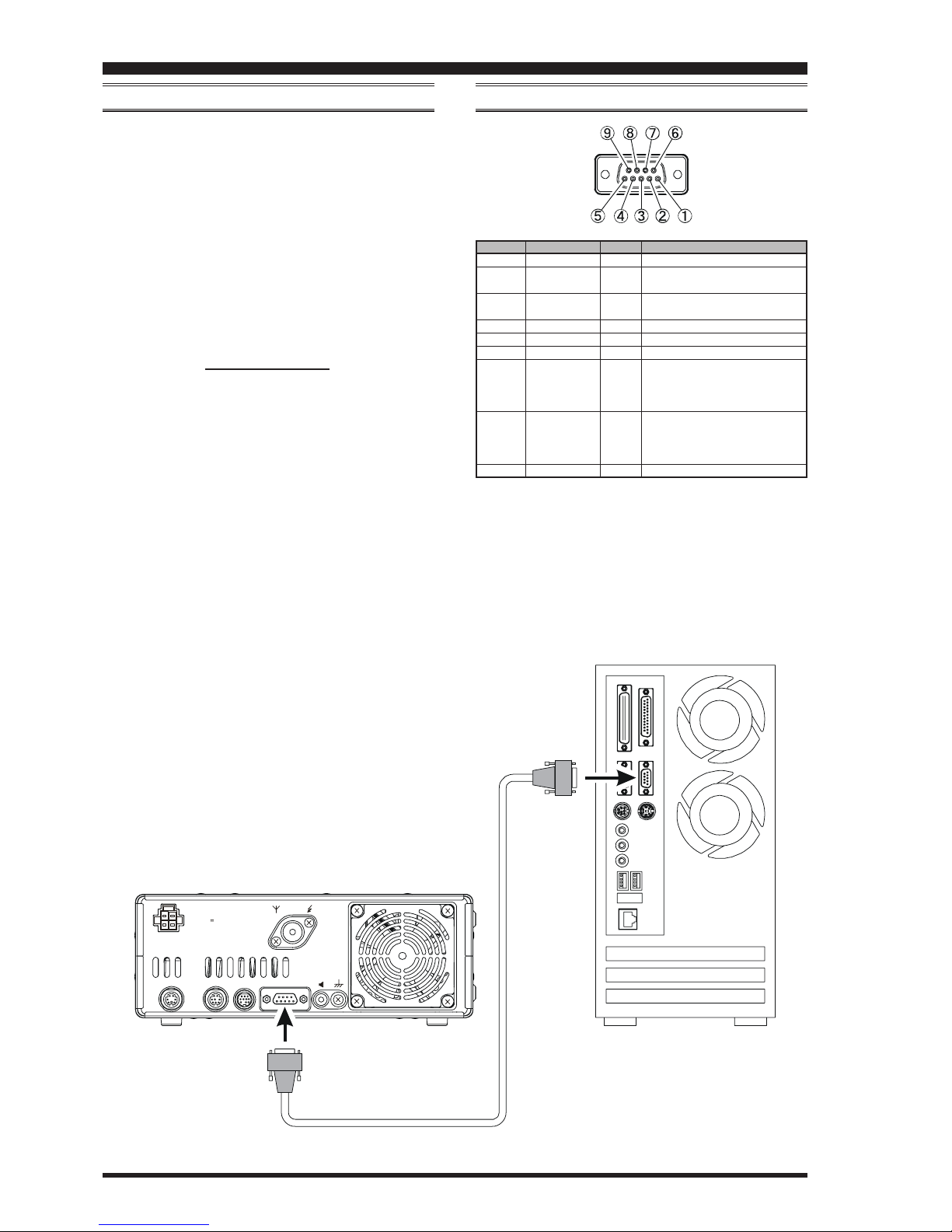
CAT (COMPUTER AIDED TRANSCEIVER)OPERATION
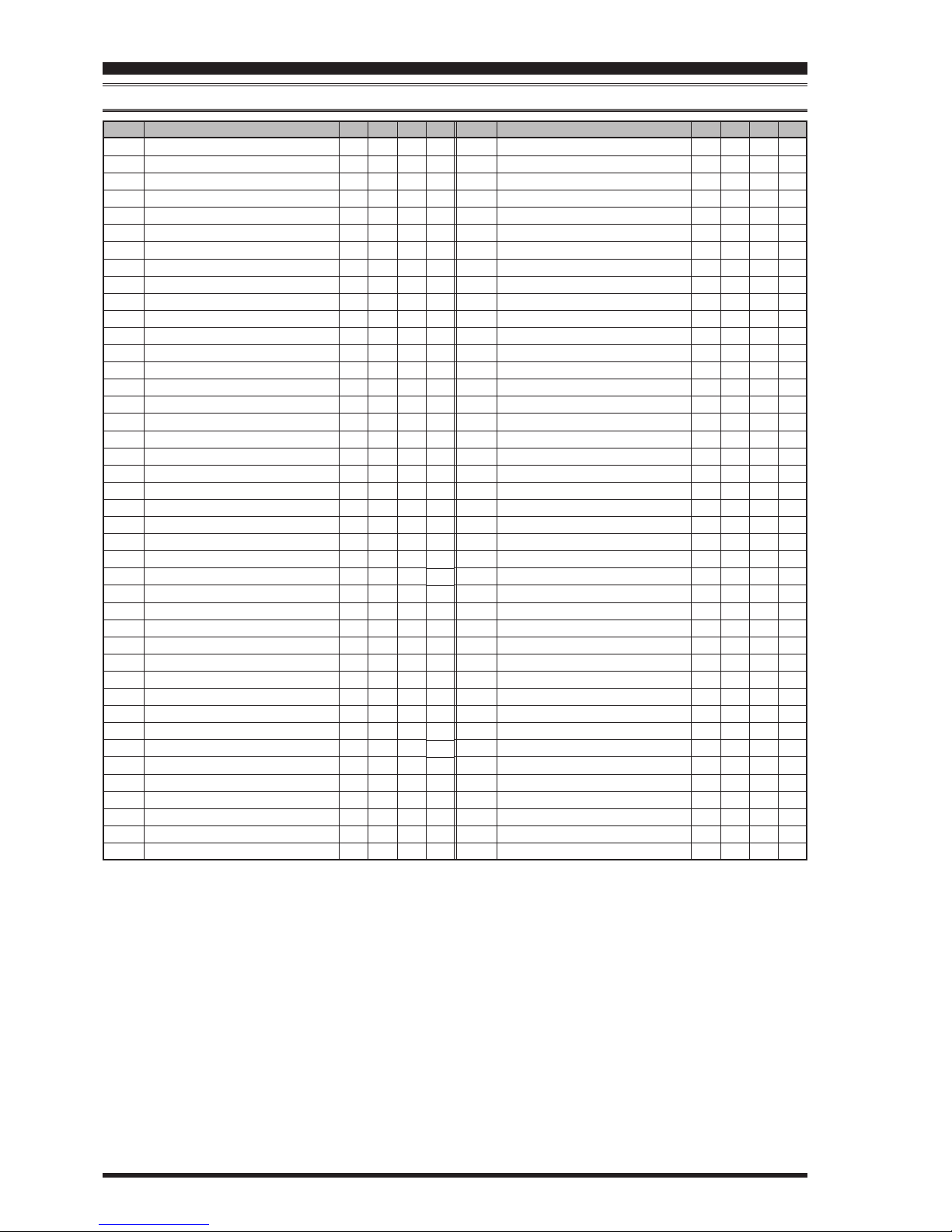
CONTROL COMMAND TABLES
P2 FUNCTION
01 MONI Activates the Monitor function.
02 N/A No Function.
03 P/B Activates the Digital Voice Recorder.
04 PLAY1 Send the CW message, which is memorized in BEACON TEXT 1.
05 PLAY2 Send the CW message, which is memorized in BEACON TEXT 2.
06 PLAY3 Send the CW message, which is memorized in BEACON TEXT 3.
07 QSPL Activates Quick Split Operation
08 SPOT Generates a CW Spot Tone when using CW mode.
09 SQLOFF Opens the noise squelch.
10 SWR Transmits a 10 watts carrier (CW mode) to measure the SWR ratio.
11 TXW Monitor the transmit frequency when Split Frequency operation is engaged.
12 VCC Display the DC supply voltage.
13 VOICE2 Announces the current S-meter reading, operating frequency (with resolution to the displayed 100 Hz digit), and operating mode.
14 VM1MONI Play back the voice message, which is memorized in Voice Memory 1.
15 VM1REC Store the voice message into Voice Memory 1.
16 VM1TX Send the voice message, which is memorized in Voice Memory 1.
17 VM2MONI Play back the voice message, which is memorized in Voice Memory 2.
18 VM2REC Store the voice message into Voice Memory 2.
19 VM2TX Send the voice message, which is memorized in Voice Memory 2.
20 DOWN Decreases the VFO frequency by one step or moves the memory channel to the next-lowest channel.
21 FAST Set to the same function as the front panel’s [FAST]button.
22 UP Increases the VFO frequency by one step or moves the memory channel to the next-highest channel.
23 DSP Set to the same function as the front panel’s [DSP]button.
24 ATT/IPO Set to the same function as the front panel’s [ATT/IPO]button.
25 NB Set to the same function as the front panel’s [NB]button.
26 AGC Set to the same function as the front panel’s [AGC]button.
27 MODEDN Set to the same function as the front panel’s [MODET]button.
28 MODEUP Set to the same function as the front panel’s [MODES]button.
29 DSP/SEL Set to the same function as the front panel’s [DSP/SEL]button.
30 KEYER Set to the same function as the front panel’s [KEYER]button.
31 CLAR Set to the same function as the front panel’s [CLAR]button.
32 BANDDN Set to the same function as the front panel’s [BANDT]button.
33 BANDUP Set to the same function as the front panel’s [BANDS]button.
34 A=B Set to the same function as the front panel’s [A=B]button.
35 A/B Set to the same function as the front panel’s [A/B]button.
36 LOCK Set to the same function as the front panel’s [LOCK]button.
37 TUNE Set to the same function as the front panel’s [TUNE]button.
38 VOICE Announce the current operating frequency (with resolution to the displayed 100 Hz digit)and operating mode.
39 MW Copies the current operating data from the VFO into the currently selected memory channel.
40 V/M Toggles frequency control between VFO and memory system.
41 HOME Recall the “Home” (favorite frequency)channel.
42 RCL Recall the QMB (Quick Memory Bank)memory.
43 VOX Activate the VOX (automatic voice-actuated transmitter switching)feature.
44 STO Copies operating data into QMB (Quick Memory Bank)Memory.
45 STEP Enables the setting of the frequency step of the [DSP/SEL]knob by the [DSP/SEL]knob.
46 SPLIT Activates split frequency operation between VFO-A and VFO-B.
47 PMS Engages Programmable Memory Scan (PMS).
48 SCAN Initiates the upward scanning of VFO frequencies or memory channels.
49 MENU Engage the “Menu” mode.
50 DIMMER Enables adjustment of the display dimmer level by the [DSP/SEL]knob.
51 MTR Change the meter function in the transmit mode.
TABLE 6
00
01
02
03
04
05
06
07
08
67.0 Hz
69.3 Hz
71.9 Hz
74.4 Hz
77.0 Hz
79.7 Hz
82.5 Hz
85.4 Hz
88.5 Hz
09
10
11
12
13
14
15
16
17
91.5 Hz
94.8 Hz
97.4 Hz
100.0 Hz
103.5 Hz
107.2 Hz
110.9 Hz
114.8 Hz
118.8 Hz
123.0 Hz
127.3 Hz
131.8 Hz
136.5 Hz
141.3 Hz
146.2 Hz
151.4 Hz
156.7 Hz
159.8 Hz
27
28
29
30
31
32
33
34
35
162.2 Hz
165.5 Hz
167.9 Hz
171.3 Hz
173.8 Hz
177.3 Hz
179.9 Hz
183.5 Hz
186.2 Hz
36
37
38
39
40
41
42
43
44
189.9 Hz
192.8 Hz
196.6 Hz
199.5 Hz
203.5 Hz
206.5 Hz
210.7 Hz
218.1 Hz
225.7 Hz
45
46
47
48
49
---
---
---
---
229.1 Hz
233.6 Hz
241.8 Hz
250.3 Hz
254.1 Hz
---
---
---
---
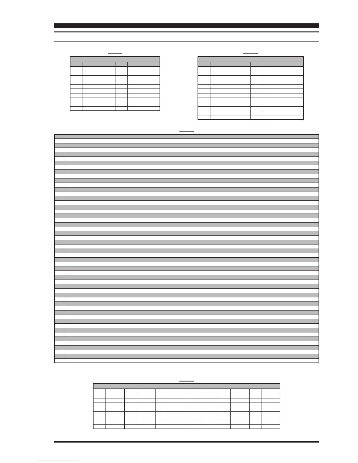
CTCSS TONE CHART
18
19
20
21
22
23
24
25
26
TABLE 5
Page 8
TABLE 3
P2
000
001
003
004
005
006
007
008
009
010
FUNCTION
1.8 MHz “OFF”
3.5 MHz “OFF”
7 MHz “OFF”
10 MHz “OFF”
14 MHz “OFF”
18 MHz “OFF”
21 MHz “OFF”
24.5 MHz “OFF”
28 MHz “OFF”
50 MHz “OFF”
MY BAND
P2
100
101
103
104
105
106
107
108
109
110
FUNCTION
1.8 MHz “ON”
3.5 MHz “ON”
7 MHz “ON”
10 MHz “ON”
14 MHz “ON”
18 MHz “ON”
21 MHz “ON”
24.5 MHz “ON”
28 MHz “ON”
50 MHz “ON”
P2
01
02
03
04
05
06
07
08
09
0A
0B
0C
FUNCTION
LSB “OFF”
USB “OFF”
CW “OFF”
FM “OFF”
AM “OFF”
DATA (RTTY-LSB) “OFF”
CW-R “OFF”
USER-L “OFF”
DATA (RTTY-USB) “OFF”
N.A.
FM-N “OFF”
USER-U “OFF”
MY MODE
P2
11
12
13
14
15
16
17
18
19
1A
1B
1C
FUNCTION
LSB “ON”
USB “ON”
CW “ON”
FM “ON”
AM “ON”
DATA (RTTY-LSB) “ON”
CW-R “ON”
USER-L “ON”
DATA (RTTY-USB) “ON”
N.A.
FM-N “ON”
USER-U “ON”
TABLE 4