Yaesu FT DX 3000 User manual

HF/50 MHz Transceiver
FT DX 3000
OperaTing Manual
YAESU MUSEN CO., LTD.
Tennozu Parkside Building
2-5-8 Higashi-Shinagawa, Shinagawa-ku, Tokyo 140-0002 Japan
YAESU USA
6125 Phyllis Drive, Cypress, CA 90630, U.S.A.
YAESU UK
Unit 12, Sun Valley Business Park, Winnall Close
Winchester, Hampshire, SO23 0LB, U.K.

About this MAnuAl . . .
The FTDX3000 is a leading-edge transceiver with a number of new and exciting features, some of which may be unfa-
miliar to you. In order to gain the most enjoyment and operating efciency from your FTDX3000, we recommend that
you read this manual in its entirety, and keep it handy for reference as you explore the many capabilities of your new
transceiver.
Before using your FTDX3000, be sure to read and follow the instructions in the “Before You Begin” section of this man-
ual.

Page 1
FT DX 3000 OperaTing Manual
General Description
Congratulations on the purchase of your Yaesu amateur
transceier If this is your rst rig or if aesu euipment
is already the acone of your station rest assured
your transceiver will provide many hours of operating
pleasure for years to come.
The FTDX3000 is an elite-class HF transceiver provid-
ing exceptional performance both on transmit and re-
ceive. The FTDX3000 is designed for the most competi-
tie operating situations hether you primarily operate
in contest or digitalmode enironments.
Built on the foundation of the popular FTDX9000 trans-
ceier and carrying on the proud tradition of the FT-
1000 series the FTDX3000 provides up to 100 Watts
of poer output on and atts
carrier. igital ignal rocessing is utilied
throughout the design proiding leadingedge transmit-
ter and receiver performance.
For exceptional protection from strong signal interfer-
ence the optional uning its may e connected
ia the rear panel. he uning its proide etraor-
dinarily sharp selectivity and protect your receiver from
close-in interference on a crowded band.
In the front end you may select one of to pream-
pliers or I Intercept oint ptimiation proiding
direct feed to the rst mier. hree leels of attenua-
tion are available in 6-dB steps.
The FTDX3000 receier utilies ltering incorpo-
rating many of the features of the FTDX9000 such as
ariale andidth I hift and assand ontour
tuning. lso proided are igital oise eduction igi-
tal utootch iltering and a manually tuned I otch
lter.
n the transmit side the aesu eclusie hreeand
arametric icrophone ualier allos precise and
flexible adjustment of the waveform created by your
oice and microphone. he audio mplitude enter
reuency and andidth are adjusted separately for
the lo midrange and highfreuency audio spectrum.
The transmitted bandwidth may also be adjusted.
danced features include irect eyoard reuency
ntry and and hange peech rocessor I onitor
for oice modes itch control pot sitch
ull essage emory adjustale I
oise laner and all mode uelch. hree
antenna ports are provided on the rear panel. Two key
jacs are proided one on the front and one on the rear
panel. he ey jacs may e congured independently
for paddle input connection to a straight ey or com-
puter-driven keying interface.
reuency setup is straightforard on the FTDX3000.
nter freuency directly for oth and .
eparate eys are aailale for and selection. ach
and ey proides three separate settings for three
different parts of each band. You may create three inde-
pendent settings of freuency mode and lter for
each band.
In addition memories are proided to store reuen-
cy ode I lter selection larier offset and can
sip status. hats more fie uicrecall
memories can instantly store operational settings at the
push of a button.
The built-in antenna tuner includes 100 memories that
automatically store antenna matching settings for rapid
later automatic recall.
Interfacing for digital modes is extremely simple with
the FTDX3000 thans to the dedicated con-
nection jac on the rear panel. ptimiation of the lter
passand settings carrier insertion point and dis-
play offset for digital modes is possile ia the enu
programming system.
danced technology is only part of the FTDX3000
story. Yaesu stands behind our products with a world-
wide network of dealers and service centers. We greatly
appreciate your investment in the FTDX3000 and e
look forward to helping you get the most enjoyment
from your ne transceier. lease feel free to contact
your nearest dealer or one of aesus national headuar-
ters ofces for technical adice interfacing assistance
or accessory recommendation. atch aesu ...s
ome age for latereaing information aout tan-
dard orion and aesu products http.yaesu.
com.
lease read this manual thoroughly to gain maimum
understanding of the full capability of the FTDX3000.
We thank you again for your purchase!

Page 2 FT DX 3000 OperaTing Manual
table of contents
General Description ..................................................... 1
Accessories & Options ................................................. 4
upplied ccessories ................................................ 4
ailale ptions .....................................................
Before You Begin .......................................................... 6
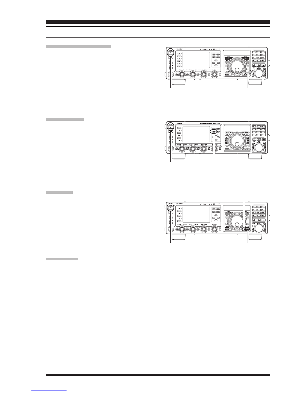
tending the ront eet .......................................... 6
djusting the ain uning ial orue .................. 6
esetting the icroprocessor ................................... 7
esetting emories nly ................................ 7
enu esetting ................................................... 7
ull eset ............................................................ 7
Installation and Interconnections ............................... 8
ntenna onsiderations ........................................... 8
out oaial ale ................................................ 8
Grounding .................................................................
onnection of ntenna and oer ales ............. 10
onnection of icrophone and eadphone ........... 11
ey eyer and omputerrien eying
Interconnections .....................................................
inear mplier Interconnections .......... 13
Interfacing to ther inear mpliers ................... 14
Plug/Connector Pinout Diagrams ............................. 15
Front Panel Controls & Switches ............................. 16
Display Indications..................................................... 26
Rear Panel ................................................................... 29
FH-2 Switches ............................................................. 31
Basic Operation: Receiving on Amateur Bands ...... 32
peration on eter and
. and .. ersion only ...................................
larier peration ................................... 36
..................................................................... 37
I ............................................................... 37
Convenience Features ................................................ 38
sing the .................................................... 38
and tac peration .............................................
. ustom itch ..............................................
Scope ...................................................................... 40
otator ontrol unctions ......................................
ore reuency aigation echniues ............... 43
eyord reuency ntry ................................ 43
sing the no ...................... 43
sing the sitches of
he supplied B8 and icrophone ....... 43
Interference Rejection ............................................... 44
. udio layac from
eceier .......... 44
eceier peration ront nd loc iagram ...
......................................................................... 46
une ilter .......................................................... 47
I Intercept oint ptimiation ........................
. oong ilters ..........................................
I oise laner peration ..........................
ontrol peration ..............................
I I peration ...............................................
I I andidth uning ....................
Using IF Shift and Width Together ...................
neouch I ilter election
I otch ilter peration .......................................
igital otch ilter peration ....................
igital oise eduction peration ............
ain odes ............................
Tools for Comfortable and Effective Reception ...... 59
udio itch ontrol ...............................................
ute eature ..........................................................
utomatic ain ontrol ............................. 60
SSB/AM Mode Transmission .................................... 62
Using the Automatic Antenna Tuner ........................ 60
peration ....................................................... 64
out peration ............................................
Enhancing Transmit Signal Quality ......................... 66
arametric icrophone ualier .......................... 66
sing the peech rocessor ................................... 68
djusting the ransmitted andidth ...........
Transmitter Convenience Features .......................... 70
oice emory ........................................................ 70
oice emory peration from the
emote ontrol eypad ......... 70
utomatic itching using oice ontrol ...........
I ............................................................. 73
plit peration sing the larier .................. 74
plitreuency peration .....................................
uic plit peration .......................................

Page 3
FT DX 3000 OperaTing Manual
table of contents
CW Mode Operation ................................................. 76
etup for traight ey
and traight ey emulation peration .......... 76
sing the uiltin lectronic eyer ....................... 77
ull reain peration ........................ 78
etting the eyer eight otash) atio ...... 78
electing the eyer perating ode ...............
CW Convenience Features ........................................ 80
udio ea ilter ................................................... 80
potting eroeating .................................. 81
sing the eroing ystem .................... 81
sing the ystem ................................... 81
sing eerse .................................................
elay ime etting ......................................... 83
itch djustment ............................................. 83
ontest emory eyer
sing the emote ontrol eypad
........ 84
essage emory ............................................. 84
emory ................................................. 86
ecode ............................................................
FM Mode Operation .................................................. 90
asic peration ......................................................
epeater peration .................................................
one uelch peration .........................................
Memory Operation .................................................... 93
onenient emory functions ...............................
uic emory an .................................
tandard emory peration ..................................
emory torage ...............................................
emory hannel ecall ...................................
aeling emories ...........................................
hecing emory hannel tatus ...................
rasing emory hannel ata ........................
oing emory ata to the register ..
emory une peration ..................................
emory roups .....................................................
emory roup ssignment .............................
hoosing the esired emory roup ..............
Operation on Alaska Emergency Frequency:
5167.5 kHz (U.S. Version Only) ..... 99
VFO and Memory Scanning ................................... 100
canning ...................................................... 100
emory can ....................................................... 101
PMS (Programmable Memory Scan) ..................... 102
RTTY (Radio Teletype) Operation ......................... 104
ecode ....................................................... 104
et emory .............................................
ample of onnecting
ommunications eice ............
Data (PSK) Operation ............................................. 106
ecode ......................................................... 106
et emory ................................................ 107
ample of ommunications eice ........ 107
Menu Mode ............................................................... 108
sing the enu .................................................... 108
enu ode eset ................................................ 108
Installation of Optional Accessories ....................... 128
arro ilter ...........................
oice emory nit ...............................
ternal utomatic
ntenna uner for ire ntenna ...... 130
F Tuning it ....................................................
Specications ............................................................ 134

Page 4 FT DX 3000 OperaTing Manual
accessories & options
Supplied AcceSSorieS
Hand icrophone MH-31B8) pc
emote ontrol eypad FH-2) 1 pc
oer ord pc
pare use 25A) 1 pc Q0000074
lug pcs
perating anual pc
Warranty Card 1 pc

Page 5
FT DX 3000 OperaTing Manual
accessories & options
AvAilAble optionS
MD-200A8X ltraighidelity estop icrophone
MD-100A8X estop icrophone
YH-77STA Lightweight Stereo Headphone
VL-1000/VP-1000 inear mplier oer upply
RF µTuning Kit A For 160 m Band
RF µTuning Kit B or m ands
RF µTuning Kit C or m ands
FC-40 ternal utomatic ntenna uner
DVS-6 oice emory nit
XF-127CN arro ilter
CT-178 VL-1000 inear mplier onnection ale
CT Cable I I m ntenna otator onnection ale
MD-200A8X YH-77STA FH-2
VL-1000/VP-1000
RF µTuning Kit DVS-6FC-40
XF-127CN

Page 6 FT DX 3000 OperaTing Manual
extending the Front Feet
o eleate the front panel for easy ieing the front left and right feet on the case ottom may e etended.
ull the front legs outard from the ottom panel.
otate the legs counterclocise to loc them in
the extended position. Be sure the legs have locked
securely in place ecause the transceier is uite
heay and an unloced leg could result in damage
should the transceiver move suddenly.
Retracting the Front Feet
otate the legs clocise and push them inard
while continuing to rotate clockwise.
The front feet should now be locked in the retracted
position.
AdjuSting the MAin tuning diAl torque
he torue drag of the ain uning ial no may e
adjusted according to your preferences. Simply hold the
rear sirt in place and rotate the no clocise to re-
duce the drag or counterclocise to increase the drag.
before You beGin
Hold the Skirt

Page 7
FT DX 3000 OperaTing Manual
[POWER] button [A
M] button
before You beGin
reSetting the MicroproceSSor
reSetting MeMorieS (only)
se this procedure to reset clear the preiously stored
emory channels ithout affecting any conguration
changes you may hae made to the enu settings.
. ress the front panels [POWER switch to turn the
transceiver off.
. hile holding the [A
M utton in press and hold
in the front panel [POWER switch to turn the trans-
ceier on. nce the transceier comes on you may
release the buttons.
Menu reSetting
se this procedure to restore the enu settings to their
factory defaults ithout affecting the memories you
have programmed.
. ress the front panel [POWER switch to turn the
transceiver off.
. hile holding the [MENU utton in press and hold
in the front panel [POWER switch to turn the trans-
ceier on. nce the transceier comes on you may
release the buttons.
Full reSet
se this procedure to restore all enu and emory set-
tings to their original factory defaults. ll emories ill
be cleared by this procedure.
. ress the front panel [POWER switch to turn the
transceiver off.
. hile holding the [FAST and [LOCK uttons in
press and hold in the front panel [POWER switch
to turn the transceier on. nce the transceier
comes on you may release the uttons.
iMportAnt note:
hen the optional uning it is connected to the
FTDX3000 disconnect all the cales from the uning
it efore performing the ull eset.
[LOCK] button
[FAST] button
[POWER] button [MENU] button
[POWER] button

Page 8 FT DX 3000 OperaTing Manual
AntennA conSiderAtionS
The FTDX3000 is designed for use ith any antenna system proiding a hm resistie impedance at the desired op-
erating freuency. hile minor ecursions from the hm specication are of no conseuence if the tanding ae
atio present at the ntenna jac is greater than the transceiers utomatic ntenna uner may not e ale
to reduce the impedance mismatch to an acceptable value.
ery effort should e made to ensure that the impedance of the antenna system e as close as possile to the specied
hm alue. ote that the type antenna does not proide a hm impedance on all mateur ands. n
external wide-range antenna coupler must be used with this antenna type.
ny antenna to e used ith the FTDX3000 must e fed from the transceier ith hm coaial cale. herefore
hen using a alanced antenna such as a dipole rememer that a alun or other matchingalancing deice must e
used to ensure proper antenna performance.
he same precautions apply to any additional receieonly antennas connected to the antenna jacs. if your receie
only antennas do not hae impedance near hms at the operating freuency you may need to install an eternal an-
tenna tuner to obtain optimum performance.
About coAxiAl cAble
se highuality hm coaial cale for the leadin to your FTDX3000 transceier. ll efforts at proiding an ef-
cient antenna system ill e asted if poor uality lossy coaial cale is used. his transceier utilies standard
type connectors.
installation anD interconnections
typicAl pl-259 inStAllAtion

Page 9
FT DX 3000 OperaTing Manual
installation anD interconnections
proper ground connection iMproper ground connection
grounding
The FTDX3000 transceier lie any other communications apparatus reuires an effectie ground system for mai-
mum electrical safety and est communications effectieness. good ground system can contriute to station efciency
in a numer of ays
It can minimie the possiility of electrical shoc to the operator.
It can minimie currents oing on the shield of the coaial cale and the chassis of the transceier. such cur-
rents may lead to radiation hich can cause interference to home entertainment deices or laoratory test euip-
ment.
It can minimie the possiility of erratic transceieraccessory operation caused y feedac andor improper
current o through logic deices.
n effectie earth ground system may tae seeral forms. for a more complete discussion see an appropriate engi-
neering text. The information below is intended only as a guideline.
ypically the ground connection consists of one or more copperclad steel rods drien into the ground. If multiple
ground rods are used they should e positioned in a conguration and onded together at the ase of the hich
is nearest the station location. se a heay raided cale such as the discarded shield from type coaial cale
and strong cale clamps to secure the raided cales to the ground rods. e sure to eatherproof the connections
to ensure many years of reliale serice. se the same type of heay raided cale for the connections to the station
ground us descried elo.
Inside the station a common ground us consisting of a copper pipe of at least mm diameter should e used. n al-
ternatie station ground us may consist of a ide copper plate singlesided circuit oard material is ideal secured to
the ottom of the operating des. rounding connections from indiidual transceiers poer supplies and data com-
munications deices s etc. should e made directly to the ground us using a heay raided cale.
o not aisyhain ground connections from one electrical deice to another and thence to the ground us. his
method may nullify any attempt at effectie radio freuency grounding. ee the draing elo for eamples of proper
grounding techniues.
Inspect the ground system - inside the station as well as outside - on a regular basis to ensure continued performance
and safety.
esides folloing the aoe guidelines carefully note that household or industrial gas lines must neer e used in an
attempt to estalish an electrical ground. old ater pipes may in some instances help in the grounding effort ut gas
lines represent a signicant eplosion haard and must neer e used.

Page 10 FT DX 3000 OperaTing Manual
connection oF AntennA And power cAbleS
lease follo the outline in the illustration regarding the proper connection of antenna coaial cales as ell as the
poer cale. he poer connector for the FT
DX
3000 must only e connected to a source proiding . olts
and capale of at least mperes of current. lays osere proper polarity hen maing connection
The RED DC power lead connects to the Positive (+) DC terminal.
The BLACK DC power lead connects to the Negative (–) DC terminal.
We recommend the use of the FP-1030A maret only oer upply. ther models of poer supplies may
be used with the FTDX3000 ut the . input oltage mpere current capaility and cale polarity
guidelines described above must be strictly followed.
ote that other manufacturers may use the same type of poer connections as does your FTDX3000 transceier
hoeer the iring conguration may e different from that specied for your transceier. erious damage can e
caused if improper connections are made consult ith a ualied serice technician hen in dout.
he oltage ohm is applied to the section of the transceier hile transmitting.
o not touch the section asolutely hile transmitting.
ermanent damage can result hen improper supply oltage or reersepolarity oltage is applied to the
FTDX3000. he imited arranty on this transceier does not coer damage caused y application of olt-
age reerse polarity or oltage outside the specied range of . . hen replacing fuses e certain
to use a fuse of the proper rating. The FTDX3000 reuires a lade fuse.
Advice:
o not position the FTDX3000 in a location with direct exposure to sunshine.
o not position the FTDX3000 in a location eposed to dust andor high humidity.
nsure adeuate entilation around the FTDX3000 to preent heat uildup and possile reduction of performance
due to high heat.
o not install the FTDX3000 on an unstale des or tale. o not place in a location here ojects may fall onto it from aoe.
o minimie the possiility of interference to home entertainment deices tae all precautionary steps including
separation of antennas from mateur transmitting antennas to the greatest etent possile and eep trans-
mitting coaxial cables separated from cables connected to home entertainment devices.
nsure that the poer cord is not suject to undue stress or ending hich could damage the cale or cause it to
be accidentally unplugged from the rear panel DC IN jack.
e certain to install your transmitting antennas so they cannot possily come in contact ith radio or other
antennas or ith poer or telephone lines.
installation anD interconnections
To prevent damage from
lightning, atmospheric elec-
tricity, electrical shock etc., please
provide a good earth ground.
se a short
th i c ra id ed
cable to con-
nect your station
euipment to the
uried ground rod or alternatie earth
ground system).
Check the DC volt-
age and current rating
(+13.8 V, 23 A) of the power
supply before connecting to the
transceiver.

Page 11
FT DX 3000 OperaTing Manual
installation anD interconnections
connection oF Microphone And heAdphone

Page 12 FT DX 3000 OperaTing Manual
Key, Keyer, And coMputer-driven Keying interconnectionS
The FTDX3000 includes many features for the operator. hese functions ill e detailed in the peration section
later. esides the uiltin lectronic eyer to ey jacs are proided one on the front and one on the rear panel for
convenient connection to keying devices.
he enu selections allo you to congure the front and rear panel KEY jacks according to the device you wish to con-
nect. or eample you may connect your eyer paddle to the front panel KEY jac and use enu item 018 KEYER F
KEYER TYPE for paddle input and also connect the eying line from your personal computer hich emulates a straight
ey to the rear panel KEY jac and congure the rear panel jac using enu item 020 KEYER R KEYER TYPE.
Both KEY jacks on the FTDX3000 utilie ositie eying oltage. eyup oltage is approimately . and
eydon current is approimately . m. hen connecting a ey or other deice to the KEY jacs use only a 3-con-
tact stereo phone plug a contact plug ill place a short eteen the ring and grounded shaft of the plug
resulting in a constant eydon condition in some circumstances.
installation anD interconnections

Page 13
FT DX 3000 OperaTing Manual
installation anD interconnections
vl-1000 lineAr AMpliFier interconnectionS
Be sure that both the FTDX3000 and VL-1000 are turned off and then follo the installation recommendations con-
tained in the illustration.
note:
lease refer to the VL-1000 perating anual for details regarding amplier operation.
lease do not attempt to connect or disconnect coaial cales hen your hands are et.
To link the FTDX3000 and VL-1000 Power
switches, set the VL-1000 REMOTE switch
to the “ON” position.
Set the front panel’s
INPUT switch to the
“INPUT2”.

Page 14 FT DX 3000 OperaTing Manual
installation anD interconnections
interFAcing to other lineAr AMpliFierS
note
he pin pin of the LINEAR jack
is a transistor open collector circuit. It is capale of
handling positie relay coil oltages up to
at m or at . If you plan to use
multiple linear amplifiers for different ands you
must proide eternal and sitching of the inear
relay control line from the line
at the LINEAR jack.
he specied range for oltage to e used ith
the FTDX3000 is to olts .
mplier systems utiliing different oltages
will not work correctly with the FTDX3000 and
their lines must not e connected if this is the
case.
iMportAnt note!
o not eceed the maimum oltage or current rat-
ings for the pin pin of the LIN-
EAR jack. This line is not compatible with negative
oltages or oltages of any magnitude.
ost amplifier control relay systems reuire only
lo oltagecurrent sitching capaility typi-
cally at m and the sitching
transistor in the FTDX3000 will easily accommodate
such ampliers.
Note
When the FC-40 is connected to the FTDX3000
pin of the TUNER jack and the
LINEAR jac pin are common circuits.
herefore the maimum oltage at pin
of the LINEAR jac must not eceed .
GND
EXT ALC
TX GND

Page 15
FT DX 3000 OperaTing Manual
pluG /connector pinout DiaGrams

Page 16 FT DX 3000 OperaTing Manual
[POWER] Switch
ress and hold in this sitch for one second to turn
the transceier on. imilarly press and hold in this
switch for one second to turn the transceiver off.
[TUNE] Switch
his is the onoff sitch for the FTDX3000s uto-
matic ntenna uner.
ressing this utton momentarily places the antenna
tuner in line eteen the transmitter nal amplier
and the antenna jac he TUNER icon ill ap-
pear in the display. eception is not affected.
ressing and holding in this utton for to seconds
hile receiing in an amateur and actiates the
transmitter for a few seconds while the automatic
antenna tuner rematches the antenna system imped-
ance for minimum . he resulting setting is au-
tomatically stored in one of the antenna tuner’s 100
memories for instant automatic recall later when the
receier is tuned near the same freuency.
ressing this utton momentarily hile the uner is
engaged ill tae the utomatic ntenna tuner out
of the transmit line.
note:
hen the utomatic ntenna uner is tuning itself
a signal is eing transmitted. herefore e certain
that an antenna or dummy load is connected to the
selected antenna jack before pressing and holding in
the [TUNE switch to start antenna tuning.
KEY Jack
his inch contact jac accepts a ey or
eyer paddles for the uiltin electronic eyer
or output from an eternal electronic eyer. inout
is shown on page . ey up oltage is .
and ey don current is m. his jac may
e congured for eyer ug straight ey or
computer eying interface operation ia enu item
018 F CW KEYER see page . here is anoth-
er jack with the same name on the rear panel and it
may e congured independently for Internal eyer
or pseudo-straight-key operation.
note:
ou cannot use a contact plug in this jac to do so
produces a constant ey don condition.
front panel controls & switches

Page 17
FT DX 3000 OperaTing Manual
front panel controls & switches
PHONES Jack
inch contact jac accepts either monaural or
stereo headphones ith or contact plugs. hen
a plug is inserted the loudspeaer is disaled.
note:
hen earing headphones e recommend that you
turn the ain leels don to their loest settings
efore turning poer on to minimie the impact on
your hearing caused y audio pops during sitch
on.
Microphone Connector
This 8-pin jack accepts input from a microphone uti-
liing a traditional transceier pinout.
[ANT] Switch
ressing this sitch selects the ANT 1 ANT 2 or
the ANT 3 connector on the rear panel and allos
convenient antenna switching at the press of a but-
ton. The selected antenna jack is indicated on the
loc iagram isplay shown in the Transceiver
isplay.
Advice:
he jac enales to use as an antenna for re-
ception only using the enu item -
I. ee page .
[IPO] (
intercept point optiMizAtion
) Switch
This button may be used to set the optimum front
end characteristics of the receiver circuit for a very
strong signal enironment. ailale selections are
lo distortion amplifier stage
lodistortion amplifier or I ypasses the
front end amplifier. he selected receier
amplifier appears in the I column of the loc
iagram isplay on the display.
[ATT] Switch
his utton selects the degree of attenuation if any
to be applied to the receiver input.
ailale selections are d d d or
. he attenuation leel appears in the col-
umn of the loc iagram isplay on the display.
Advice:
he ttenuator may e used in conjunction ith the
[IPO button to provide two stages of signal reduc-
tion when an extremely strong signal is being re-
ceived.
[R.FLT] (
rooFing Filter
) Switch
his utton selects the andidth of the receier rst
I oong ilter. ailale selections are *
or uto.
he selected andidth appears in the . column
of the loc iagram isplay on the display.
euires optional arro ilter.
Advice:
he selection mode selects the optimum
andidth of the oong lter for the reception
mode. In this case the selected andidth in
the . column of the loc iagram is-
play glos yello he unselected choices glo
Blue).
ecause the roofing filter is in the first I the
protection it provides against interference is
uite signicant. hen set to
and the andidth is hile
and is . n a croded and
hoeer you may ish to select the l-
ter for the maimum possile interference rejec-
tion.
[NB] Switch
his utton turns the I oise laner on and off.
ress this utton momentarily to reduce shortdura-
tion pulse noise.
ailale selections are or . he
attenuation leel appears in the column of the
loc iagram isplay on the display.
[AGC] Switch
his utton selects the characteristics for the
receier. ailale selections are I
and or . he selected characteris-
tics appear in the column of the loc iagram
isplay on the display.
ress the [AGC button repeatedly to select the de-
sired receierrecoery time constant. ress and hold
in the [AGC button for one second to disable the
for testing or easignal reception.
Advice:
he selection mode selects the charac-
teristics of the for the reception mode. he
selected characteristics ill glo green in
the column of the loc iagram isplay
unselected characteristics glo lue.
he ttenuator may e used in conjunction ith
the [IPO button to provide two stages of signal
reduction when an extremely strong signal is be-
ing received.
If the receierrecoery time is set to ff
by pressing and holding in the [AGC utton the
meter ill no longer deect. dditionally you
will likely encounter distortion on stronger sig-
nals as the I ampliers and the folloing stages
are probably being overloaded.
[MOX] Switch
ressing this utton engages the ush to al
circuit to actiate the transmitter the inside
this utton ill glo red. It must e turned off the
red ill e off for reception. his utton repli-
cates the action of the ush to al sitch on
the microphone. When engaging the [MOX utton
or otherise causing a transmission to e started
e certain you hae either an antenna or hm
dummy load connected to the selected ntenna jac.

Page 18 FT DX 3000 OperaTing Manual
[MIC/SPEED] Knob
MIC
This knob adjusts the microphone input level for
nonprocessed transmission.
The display will show the relative microphone gain
level for 3 seconds whenever this knob is turned.
Advice:
djust the [MIC/SPEED knob while speaking in a
somehat louder than normal oice leel atch the
leel and adjust the [MIC/SPEED knob so
that the leel indication just reaches the right
edge of the scale. hen hen you spea in
your normal oice leel you ill not e oerdriing
the microphone amplier stages.
SPEED
This knob adjusts the keying speed of the internal
eyer . locise rotation in-
creases the sending speed.
The display will show the keying speed for 3 sec-
onds whenever this knob is turned.
[PROC/CAR] Knob
PROC
his no adjusts the compression input leel
of the transmitter speech processor in the
mode.
CAR
his no adjusts the oer arrier output of
the transceier. or the mode set the desired
maimum oer output ia enu item 177 TX
MAX POWER see page .
iMportAnt note:
he setting alue of enu item 177 TX MAX
POWER is applied to all emission modes.
For example hen enu item 177 TX MAX
POWER is set to 50 the maimum oer
output for all emission modes is 50 een if the
[PROC/CAR knob is set to the fully clockwise po-
sition.
Advice:
he oer output setting ill e shon for
seconds in the right of the TFT display whenever the
outer [PROC/CAR no is turned ecept hen
177 TX MAX POWER is set to atts.
In the SSB mode the [PROC value will be shown
instead of the oer output.
front panel controls & switches
Other manuals for FT DX 3000
5
Table of contents
Other Yaesu Transceiver manuals

Yaesu
Yaesu FT-DX-400 User manual

Yaesu
Yaesu FT-70DR User manual

Yaesu
Yaesu FT-817 - User manual

Yaesu
Yaesu FTM-100DR User manual

Yaesu
Yaesu FT-2700RH User manual

Yaesu
Yaesu FT-4XR User manual

Yaesu
Yaesu FT-857D Owner's manual

Yaesu
Yaesu FT-707 Manual

Yaesu
Yaesu FT-7100M User manual

Yaesu
Yaesu FTA-850L User manual