National Instruments PXIe-5842 User manual

PXIe-5842 Getting Started2023-03-29

ContentsPXIe-5842 Product Overview. . . . . . . . . . . . . . . . . . . . . . . . . . . . . . . . . . . . . . . . . . . . . . . . . . . . 3
PXIe-5842 Soware Setup. . . . . . . . . . . . . . . . . . . . . . . . . . . . . . . . . . . . . . . . . . . . . . . . . . . . . . . 7
Installing and Interconnecting PXIe-5842 Instruments. . . . . . . . . . . . . . . . . . . . . . . . . . . . . . 9
PXIe-5842 Operation Guidelines. . . . . . . . . . . . . . . . . . . . . . . . . . . . . . . . . . . . . . . . . . . . . . . . 17
Setting up the PXIe-5842 for Measurements. . . . . . . . . . . . . . . . . . . . . . . . . . . . . . . . . . . . . . 19
Using NI Soware with the PXIe-5842. . . . . . . . . . . . . . . . . . . . . . . . . . . . . . . . . . . . . . . . . . . 24
PXIe-5842 Troubleshooting. . . . . . . . . . . . . . . . . . . . . . . . . . . . . . . . . . . . . . . . . . . . . . . . . . . . . 29
PXIe-5842 Instrument Interface Descriptions. . . . . . . . . . . . . . . . . . . . . . . . . . . . . . . . . . . . . 33
ni.com2PXIe-5842 Getting Started

PXIe-5842 Product Overview
What is the PXIe-5842?The PXIe-5842 is a modular RF vector signal transceiver (VST). The PXIe-5842
module combines with other modules to form complete PXIe-5842 instruments.
The PXIe-5842 combines a vector signal generator and vector signal analyzer with
FPGA-based, real-time signal processing and control.
The PXIe-5842 name encompasses the following instruments:
Table 1. PXIe-5842 Instruments
Instrument Constituent Modules
PXIe-5842 VST ■PXIe-5842
■PXIe-5655
Components of a PXIe-5842 SystemThe PXIe-5842 is designed for integration into a broader test system that requires
test soware, drivers, and, in addition to the parts included in your kit, hardware
beyond the PXIe-5842 itself. Use the following list of typical PXIe-5842 system
components as a starting point for building your test system.
PXIe-5842 VST Kit Contents■PXIe-5842
■PXIe-5655
■Cables
Cable Type Part Number Quantity
Semi-rigid cable, PXIe-5842
REF: IN to PXIe-5655
136103A-01 1 © National Instruments3PXIe-5842 Getting Started

Cable Type Part Number Quantity
REF OUT, 2.92 mm to
2.92 mm
Semi-rigid cable, PXIe-5842
RF OUT: LO IN to PXIe-5655
LO 0 OUT, 2.92 mm to
2.92 mm
136104A-01 1
Semi-rigid cable, PXIe-5842
RF IN: LO IN to PXIe-5655
LO 1 OUT, 2.92 mm to
2.92 mm
136106A-01 1
■SMA driver bit
■Screwdriver
■PXIe-5842 Safety, Environmental, and Regulatory Information
■PXIe-5655 Safety, Environmental, and Regulatory Information
Other Hardware ComponentsA complete PXIe-5842 system also requires equipment that is not included in the kit
for your PXIe-5842 instrument.
■A PXI Express chassis. Use a chassis capable of meeting the conditions
stated in the Conditions section of the PXIe-5842 Specifications and in
PXIe-5842 System Requirements.
■A PXI Express embedded controller or MXI controller compatible with your
chosen chassis.
■PXI chassis slot blockers and EMC filler panels for unoccupied slots of the
chassis.
■A 0.9 N · m (8 lb · in.) calibrated torque wrench, 5/16 in., NI part number
751120-01.
■A small flat blade screwdriver.
ni.com4PXIe-5842 Getting Started

Software Components•Application development environment—Development environments that
support the development of applications that make use of the PXIe-5842 in
supported programming languages.
■LabVIEW
■LabWindows™/CVI
■C/C++
■C# (.NET)
■InstrumentStudio
•Driver software—Drivers that provide the API for controlling and taking
measurements with the PXIe-5842.
■RFmx
■NI-RFSG
■NI-RFSA
The version of the driver you install must provide support for your instrument.
Refer to the release notes or readme for a driver to determine which versions of
the driver support your instrument.
Note Driver soware should be installed aer you install any
application development environment.
Related information:■NI soware downloads
■NI soware release notes
PXIe-5842 System RequirementsYour system must meet the following minimum requirements to use the PXIe-5842.
© National Instruments5PXIe-5842 Getting Started

Chassis Requirements•Slot cooling capacity—Must be ≥82 W
•Clearances—Maintain the minimum required clearances around your PXI
Express chassis. Clearances may vary by chassis. Follow the guidelines in the
documentation for the chassis.
•Available adjacent, compatible slots—PXIe-5842 VST: 4
■3 for PXIe-5842 module
■1 for PXIe-5655 module
The modules that compose PXIe-5842 instruments can be installed in the
following PXI chassis slot types:
■PXI Express Hybrid Peripheral Slot
■PXI Express System Timing Slot
■PXI Express Peripheral Slot
•Power delivery—See PXIe-5842 Safety, Environmental, and Regulatory
Information or PXIe-5842 Specifications.
Note Power requirements may be specified on a module basis;
the chassis must provide enough power for the complete PXIe-5842
instrument.
Controller or Host Computer Requirements•RAM—4 GB. Depending on the amount of data acquired and/or processed, a
larger amount of memory may be required.
•Processor—1 GHz 64-bit (x64)
ni.com6PXIe-5842 Getting Started

PXIe-5842 Soware Setup
Choosing Your SoftwareYou can choose among multiple options for taking measurements with the
PXIe-5842.
Depending on the measurements you want to take and how you want to customize
your test system, choose the appropriate soware from the following options.
If you want to Choose
Perform physical layer measurements of
supported communications and connectivity
signals
RFmx personalities
Measure spectral performance and understand
spectral characteristics
RFmx SpecAn
Measure modulation quality, including error
vector magnitude (EVM)
RFmx Demod
Create, visualize, and play back RF waveforms RFmx Waveform Creator
Perform custom measurements or applications
that require I/Q data
NI-RFSA
Generate CW or modulated waveforms NI-RFSG
Take interactive measurements with your
instrument
InstrumentStudio
Installing the SoftwareYou must be an Administrator to install NI soware on your computer.
1. Install an ADE, such as LabVIEW or LabWindows™/CVI™.
2. Download the driver soware installer from ni.com/downloads.
NI Package Manager downloads with the driver soware to handle the
installation. Refer to the NI Package Manager Manual for more information
© National Instruments7PXIe-5842 Getting Started

about installing, removing, and upgrading NI soware using NI Package
Manager.
3. Follow the instructions in the installation prompts.
Note Windows users may see access and security messages during
installation. Accept the prompts to complete the installation.
4. When the installer completes, select Restart in the dialog box that prompts
you to restart, shut down, or restart later.
ni.com8PXIe-5842 Getting Started

Installing and Interconnecting PXIe-5842
Instruments
PXIe-5842 Installation and InterconnectionOverviewFollow this general process to complete physical setup for your PXIe-5842
instrument.
Refer to the detailed procedures in this article to complete the following tasks:
1. Unpack your kit.
2. Install the PXI Express modules of your instrument in your PXI Express chassis.
3. Read and understand the guidelines before interconnecting the modules of
your instrument.
4. Interconnect the PXI Express modules of your instrument.
Unpacking the KitNotice To prevent electrostatic discharge (ESD) from damaging the
device, ground yourself using a grounding strap or by holding a grounded
object, such as your computer chassis.
1. Touch the antistatic package to a metal part of the computer chassis.
2. Remove the device from the package and inspect the device for loose
components or any other sign of damage.
Notice Never touch the exposed pins of connectors.
Note Do not install a device if it appears damaged in any way.
© National Instruments9PXIe-5842 Getting Started

3. Unpack any other items and documentation from the kit.
Store the device in the antistatic package when the device is not in use.
Installing PXIe-5842 Modules in a PXI ExpressChassisYou need to install modules in your PXIe-5842 instrument in a specific order and
orientation to facilitate interconnection of the modules into a complete, functional
instrument.
Ensure your PXI Express chassis meets the capacity, power, and slot cooling capacity
requirements of your PXIe-5842 instrument.
Notice To prevent damage to the PXIe-5842 caused by ESD or
contamination, handle each PXI module using the edges or the metal
bracket.
Complete the following steps to install the PXI modules of your instrument in your
PXI chassis:
1. Ensure the AC power source is connected to the chassis before installing the
modules.
The AC power cord grounds the chassis and protects it from electrical damage
while you install modules.
2. Power o the chassis.
3. Inspect the slot pins on the chassis backplane for any bends or damage prior
to installation. Do not install a module if the backplane is damaged.
4. Remove the black plastic covers from all the captive screws on the front
panels for all modules.
5. Select an appropriate set of PXI chassis slots so that you can install the
modules that compose your instrument in the order indicated:
ni.com10PXIe-5842 Getting Started

Instrument Adjacent Compatible Slots Required
PXIe-5842 VST 4
Instrument Module Installation Order, Le to Right
PXIe-5842 VST 1. PXIe-5842
2. PXIe-5655
PXIe-5842 instruments can be installed in the following PXI chassis slot types:
■PXI Express Hybrid Peripheral Slot
■PXI Express System Timing Slot
■PXI Express Peripheral Slot
Use the following figure to identify compatible slots within your chassis:
Figure 1. Chassis Compatibility Symbols
1. PXI Express System Controller Slot
2. PXI Peripheral Slot
3. PXI Express Hybrid Peripheral Slot
4. PXI Express System Timing Slot
5. PXI Express Peripheral Slot
6. Touch any metal part of the chassis to discharge static electricity.
7. Place the edges of a module of your instrument into the module guides of the
appropriate slot at the top and bottom of the chassis. Slide the module into
the slot until it is fully inserted.
8. Secure the module front panel to the chassis using the front-panel mounting
screws. © National Instruments11PXIe-5842 Getting Started

Note All front panel mounting screws must be attached to the PXI
Express chassis to ensure all backplane connectors are fully mated.
Tightening the mounting screws also increases mechanical stability
and electrically connects the front panel to the chassis, which can
improve the signal quality and electromagnetic performance.
9. Repeat steps 6 through 9 for each PXI module within your instrument until you
have installed all PXI modules for your instrument.
10. Cover all empty slots using slot blockers and EMC filler panels.
Note For more information about installing slot blockers and filler
panels, go to ni.com/r/pxiblocker.
11. Power on the chassis.
The in-chassis modules of your PXIe-5842 instrument are now correctly installed in
your PXI chassis.
PXIe-5842 instruments also require interconnections between the installed
modules. Continue with the interconnection procedure for your instrument
according to the interconnection guidelines.
Ensuring Signal Quality when Interconnecting thePXIe-5842Aer you install the PXIe-5842 modules into your chassis, you must use the included
cables to interconnect the PXI Express modules to each other and subsequently to
any modules external to the PXI Express chassis. To ensure proper connections that
maintain signal quality, adhere to the following guidelines while interconnecting the
modules.
■ Inspect all RF connectors before attaching mating cables. Clean with
dry compressed air, if necessary, to remove any contaminants that may be
present.
ni.com12PXIe-5842 Getting Started

■ Position RF cables with instrument connectors to ensure center pins are
straight and aligned before mating.
■ For all threaded RF connectors for your PXIe-5842 instrument, engage and
finger-tighten the connector nuts. The connector nuts should thread easily
without binding, but if not, ensure the connector is straight and that center
pins have not been damaged.
■ Carefully tighten all threaded RF connectors to the torque specified in
the interconnection process for your instrument using an appropriate torque
wrench or torque screwdriver and driver bit; tighten only until the wrench
reaches the torque limit.
Notice Incorrect torque at threaded connections can damage
device connectors and degrade signal integrity.
Interconnecting the PXIe-5842 VSTComplete this procedure to interconnect the modules of the PXIe-5842 VST.
Before beginning this procedure, install the relevant modules for your instrument in
your PXI Express chassis and refer to the interconnection guidelines.
All PXIe-5842 instrument configurations include a PXIe-5655 module physically
adjacent to the PXIe-5842 module. These two modules are interconnected in the
same way for all PXIe-5842 instrument configurations.
Complete the following steps to interconnect the PXIe-5842 VST:
1. Connect the local oscillator for RF output.
Cable Torque PXIe-5842 Connector PXIe-5655 Connector
Semi-rigid
2.92 mm (m)-
to-2.92 mm (m),
136104A-01
0.9 N · m (8 lb · in.) RF OUT: LO IN LO 0 OUT
2. Connect the internal reference clock. © National Instruments13PXIe-5842 Getting Started

Cable Torque PXIe-5842 Connector PXIe-5655 Connector
Semi-rigid
2.92 mm (m)-
to-2.92 mm (m),
136103A-01
0.9 N · m (8 lb · in.) REF: IN REF OUT
3. Connect the local oscillator for RF input.
Cable Torque PXIe-5842 Connector PXIe-5655 Connector
Semi-rigid
2.92 mm (m)-
to-2.92 mm (m),
136106A-01
0.9 N · m (8 lb · in.) RF IN: LO IN LO 1 OUT
You have now provided the reference clock and LO sources for the PXIe-5842 VST.
Your instrument should appear as follows:
ni.com14PXIe-5842 Getting Started

Figure 2. Interconnected PXIe-5842 VST
1. PXIe-5842
2. PXIe-5655 © National Instruments15PXIe-5842 Getting Started

3. Semi-rigid 2.92 mm (m)-to-2.92 mm (m) cables
Physical setup for the PXIe-5842 VST is now complete.
ni.com16PXIe-5842 Getting Started

PXIe-5842 Operation Guidelines
Avoiding Damage when Making Direct Connectionsto the PXIe-5842Because the PXIe-5842 is a precision RF instrument, it is sensitive to ESD and
transients. When you make direct connections to the PXIe-5842, you can avoid
damaging the RF ports by adhering to the following guidelines.
■ Apply external signals only while the hardware is powered on.
Notice Applying external signals while the hardware is powered o
may cause damage.
■ Ensure you are properly grounded when manipulating cables or antennas
connected to the instrument.
■ If you are using non-insulated devices, such as an RF antenna, ensure the
devices are maintained in a static-free environment.
■ If you are using an active device, such as a preamplifier or switch routed
to the PXIe-5842, ensure that the device cannot generate signal transients
greater than the RF and DC specifications of the PXIe-5842.
Avoiding Damage when Removing Modules fromthe ChassisIf you need to move your composite instrument or remove individual modules for
any reason, take care to avoid damaging modules or cables by first disconnecting all
interconnections made between the modules of the instrument.
Notice All interconnections made between the in-chassis modules of
your composite instrument must be disconnected prior to removing any
© National Instruments17PXIe-5842 Getting Started

modules from the PXI chassis. Failure to do so could result in damage to
the modules or interconnection cables.
ni.com18PXIe-5842 Getting Started

Setting up the PXIe-5842 for Measurements
Conguring the PXIe-5842 in MAXUse Measurement & Automation Explorer (MAX) to configure your NI hardware. MAX
informs other programs about which NI hardware products are in the system and
how they are configured. MAX is automatically installed with NI-RFSA, NI-RFSG, and
RFmx.
1. Launch MAX.
2. In the configuration tree, expand Devices and Interfaces to see the list of
installed NI hardware.
Installed modules appear under the name of their associated chassis.
3. Expand your Chassis tree item.
MAX lists all modules installed in the chassis. Your default names may vary.
Note If you do not see your module listed, press <F5> to refresh the
list of installed modules. If the module is still not listed, power o the
system, ensure the module is correctly installed, and restart.
4. Record the name MAX assigns to the PXIe-5842 or, if desired, provide a custom
name to the PXIe-5842.
Use this name when programming the PXIe-5842.
5. Associate the hardware modules that compose your instrument.
Instrument Process
PXIe-5842 VST 1. Select the PXIe-5842 module to
associate.
2. In the Associated Devices section,
click the Associated LO dropdown
and choose the PXIe-5655 to associate
with the PXIe-5842 module.
3. Click Save.© National Instruments19PXIe-5842 Getting Started
This manual suits for next models
2
Table of contents
Other National Instruments Transceiver manuals
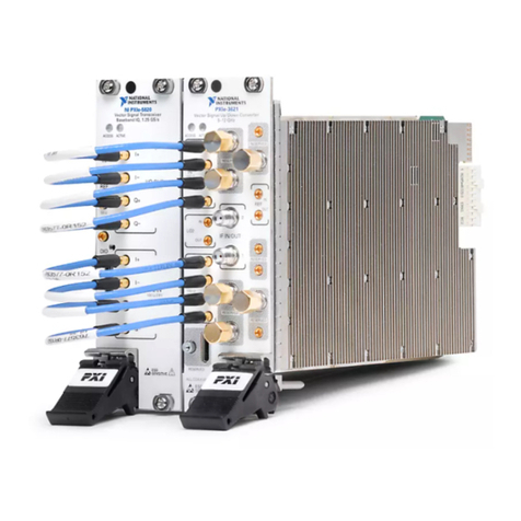
National Instruments
National Instruments NI PXIe-5644R User manual

National Instruments
National Instruments PXIe-5785 User manual

National Instruments
National Instruments PCIe-5785 User manual

National Instruments
National Instruments USRP-2950 User manual

National Instruments
National Instruments USRP-2920 User manual
National Instruments
National Instruments NI PXIe-5645R User manual

National Instruments
National Instruments USRP-2900 User manual

National Instruments
National Instruments PXIe-5646R User manual

National Instruments
National Instruments PXIe-3610 User manual
National Instruments
National Instruments PXIe-5830 User manual