Icom IC-7600 User manual

INSTRUCTION MANUAL
HF/50 MHz TRANSCEIVER
i7600

i
FOREWORD
Thank you for making the IC-7600 your radio of
choice. We hope you agree with Icom’s philosophy
of “technology first.” Many hours of research and
development went into the design of your IC-7600.
FEATURES
❍Ultimate receiver performance: third-order intercept
(IP3) of +30 dBm (HF bands only)
❍Built-in Baudot RTTY and PSK modulator/
demodulator and direct PC keyboard connection
capability for RTTY and PSK operations without a
PC
❍High resolution spectrum scope— center
frequency and fixed frequency modes, plus mini-
scope displays
❍USB connectors on front and rear panels
❍Large LCD with LED backlight
IMPORTANT
READ THIS INSTRUCTION MANUAL
CAREFULLY before attempting to operate the
transceiver.
SAVE THIS INSTRUCTION MANUAL. This
manual contains important safety and operating
instructions for the IC-7600.
EXPLICIT DEFINITIONS
WORD DEFINITION
RDANGER Personal death, serious injury or an
explosion may occur.
RWARNING Personal injury, fire hazard or electric
shock may occur.
CAUTION Equipment damage may occur.
NOTE
If disregarded, inconvenience only. No
risk of personal injury, fire or electric
shock.
Spurious signals may be received near the following
frequencies. These are made in the internal circuit
and does not indicate a transceiver malfunction.
10.4923MHz, 24.576MHz
SUPPLIED ACCESSORIES
The transceiver comes with the following accessories.
Qty.
q Hand microphone ............................................ 1
w DC power cable ............................................... 1
e CD (Instruction manual, Schematic diagram) ........ 1
r Spare fuse (5 A) .............................................. 1
t Spare fuse (30 A) ............................................ 2
y6.35 (d) mm plug ....................................................... 1
q
r
y
w
t
e
FCC INFORMATION
• FOR CLASS B UNINTENTIONAL RADIATORS:
This equipment has been tested and found to
comply with the limits for a Class B digital device,
pursuant to part 15 of the FCC Rules. These limits
are designed to provide reasonable protection against
harmful interference in a residential installation. This
equipment generates, uses and can radiate radio
frequency energy and, if not installed and used in
accordance with the instructions, may cause harmful
interference to radio communications. However, there
is no guarantee that interference will not occur in a
particular installation. If this equipment does cause
harmful interference to radio or television reception,
which can be determined by turning the equipment
off and on, the user is encouraged to try to correct the
interference by one or more of the following measures:
• Reorient or relocate the receiving antenna.
• Increase the separation between the equipment and
receiver.
•
Connect the equipment into an outlet on a circuit
different from that to which the receiver is connected.
• Consult the dealer or an experienced radio/TV
technician for help.
DISPOSAL
The crossed-out wheeled-bin symbol on
your product, literature, or packaging
reminds you that in the European Union, all
electrical and electronic products, batteries,
and accumulators (rechargeable batteries)
must be taken to designated collection
locations at the end of their working life. Do not dispose
of these products as unsorted municipal waste. Dispose
of them according to the laws in your area.
Icom, Icom Inc. and Icom logo are registered trademarks of Icom
Incorporated (Japan) in Japan, the United States, the United King-
dom, Germany, France, Spain, Russia, Australia, New Zealand, and/
or other countries.
Microsoft, Windows and Windows Vista are registered trademarks of
Microsoft Corporation in the United States and/or other countries.
All other products or brands are registered trademarks or trade-
marks of their respective holders.

PRECAUTIONS
RWARNING HIGH RF VOLTAGE! NEVER
attach an antenna or internal antenna connector
during transmission. This may result in an electrical
shock or burn.
RWARNING! NEVER operate the radio with a
headset or other audio accessories at high volume
levels. The continuous high volume operation may
cause a ringing in your ears. If you experience the
ringing, reduce the volume level or discontinue use.
RWARNING! NEVER operate or touch the radio
with wet hands. This may result in an electric shock or
damage to the radio.
RWARNING! NEVER let metal, wire or other
objects protrude into the radio or into connectors on
the rear panel. This may result in an electric shock.
RWARNING! Immediately turn the
radio
power
OFF and remove the power cable if it emits an
abnormal odor, sound or smoke. Contact your Icom
dealer or distributor for advice.
RWARNING! NEVER put the
radio
in any
unstable place (such as on a slanted surface or
vibrated place). This may cause injury and/or damage
to the
radio
.
RWARNING! NEVER apply AC power to the
[DC13.8V] connector on the
radio
rear panel. This
could cause a fire or damage the
radio
.
RWARNING! NEVER apply more than 16 V DC
to the [DC13.8V] connector on the
radio
rear panel.
This could cause a fire or damage the
radio
.
CAUTION: NEVER change the internal settings
of the
radio
. This may reduce
radio
performance and/
or damage to the
radio
.
In particular, incorrect settings for transmitter circuits,
such as output power, idling current, etc., might
damage the expensive final devices.
The
radio
warranty does not cover any problems
caused by unauthorized internal adjustment.
CAUTION: NEVER block any cooling vents on
the top, rear or bottom of the
radio
.
CAUTION: NEVER expose the
radio
to rain, snow
or any liquids.
CAUTION:
NEVER install the
radio
in a place
without adequate ventilation. Heat dissipation may be
reduced, and the
radio
may be damaged.
DO NOT use harsh solvents such as benzine or
alcohol when cleaning, as they can damage the
radio
’s surfaces.
DO NOT push the PTT switch when you don’t
actually desire to transmit.
DO NOT operate or place the
radio
in areas with
temperatures below ±0°C (+32°F) or above +50°C
(+122°F).
DO NOT place the
radio
in excessively dusty
environments or in direct sunlight.
DO NOT place the
radio
against walls or putting
anything on top of the
radio
. This may overheat the
radio
.
Always place unit in a secure place to avoid
inadvertent use by children.
BE CAREFUL! If you use a linear amplifier, set
the
radio
’s RF output power to less than the linear
amplifier’s maximum input level, otherwise, the linear
amplifier will be damaged.
BE CAREFUL! The rear panel will become hot when
operating the
radio
continuously for long periods of
time.
Use Icom microphones only (supplied or optional).
Other manufacturers’ microphones have different pin
assignments, and connection to the IC-7600 may
damage the
radio
or microphone.
The LCD display may have cosmetic imperfections
that appear as small dark or light spots. This is not a
malfunction or defect, but a normal characteristic of
LCD displays.
During maritime mobile operation, keep the
radio
and microphone as far away as possible from the
magnetic navigation compass to prevent erroneous
indications.
Turn the
radio
power OFF and/or disconnect the DC
power cable when you will not use the
radio
for long
period of time.
For U.S.A. only
CAUTION: Changes or modifications to this
device, not expressly approved by Icom Inc., could
void your authority to operate this device under FCC
regulations.
ii
1
2
3
4
5
6
7
8
9
10
11
12
13
14
15
16
17
18
19
20
21

iii
ABOUT THE SUPPLIED CD
The following instructions and installer are included
on the CD.
• Instruction manual
Instructions for full operations, the same as this
manual
• Schematic diagram
Includes the schematic and block diagrams
• HAM radio Terms
A glossary of HAM radio terms
• Adobe® Reader® Installer
Installer for Adobe®Reader®
A PC with the following Operating System is required.
• Microsoft®Windows® 8.1, Microsoft®Windows® 8,
Microsoft®Windows® 7, or Microsoft®Windows
Vista®
Starting the CDD
Insert the CD into the CD drive.q
• Double click “Menu.exe” on the CD.
• Depending on the PC setting, the Menu screen shown
below is automatically displayed.
Click the desired button to open the file.w
• To close the Menu screen, click [Quit].
To read the Instruction manual or Schematic diagram,
Adobe®Reader®is required. If you have not installed
it, please install the Adobe®Reader®on the CD or
downloaded it from Adobe Systems Incorporated’s
web
site.
Quits the Menu screen
Installs the Adobe®Reader®
Opens the
Instruction manual
(this manual)
Opens the
Schematic diagram
Opens the
Glossary

iv
1
2
3
4
5
6
7
8
9
10
11
12
13
14
15
16
17
18
19
20
21
FUNCTIONS AND FEATURES OF ADOBE®READER®
The following functions and features can be used with Adobe®Reader®.
• Keyword search
Click “Find (Ctrl+F)” or “Advanced
Search (Shift+Ctrl+F)” in the Edit
menu to open the search screen.
This is convenient when search-
ing for a particular word or phrase
in this manual.
*The Menu screen may differ, depend-
ing on the Adobe®Reader®version.
• Find screen
• Advanced search screen
Click to open the Find or Search
screen or Advanced search screen.
• Printing out the desired pages.
Click “Print...(Ctrl+P)” in File menu, and then select
the paper size and page numbers you want to print.
*The printing setup may differ, depending on the
printer. Refer to your printer’s instruction manual
for details.
*Select “A4” size to print out the page in the equal-
ized size.
• Read Out Loud feature.
The Read Out Loud feature reads aloud the text in
this Instruction Manual.
Refer to the Adobe®Reader®Help for the details.
(This feature may not be usable, depending on your
PC environment including the operating system.)
*The screen may differ, depending on the Adobe®Reader®
version.

v
TABLE OF CONTENTS
FOREWORD ............................................................. i
IMPORTANT.............................................................. i
EXPLICIT DEFINITIONS........................................... i
SUPPLIED ACCESSORIES...................................... i
FCC INFORMATION ................................................. i
DISPOSAL................................................................. i
PRECAUTIONS.........................................................ii
ABOUT THE SUPPLIED CD ....................................iii
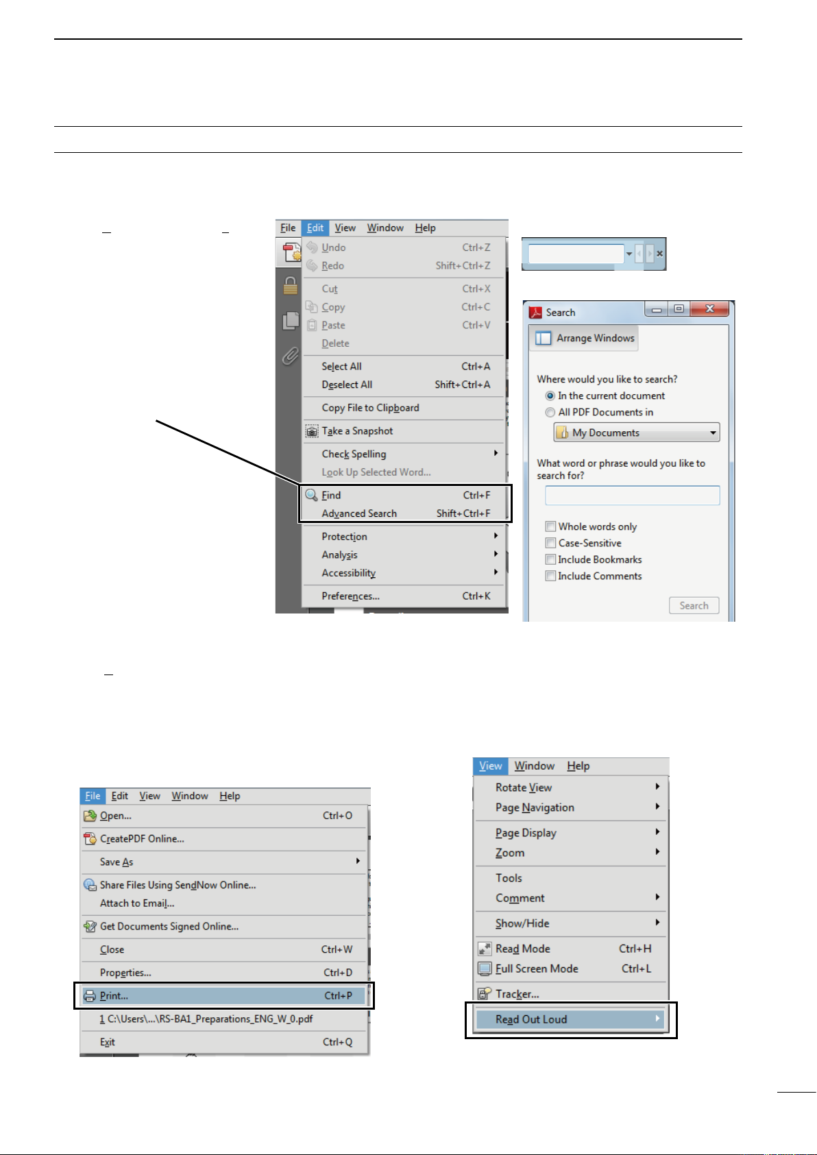
FUNCTIONS AND FEATURES of Adobe®Reader®
..iv
ABOUT THESE ADVANCED INSTRUCTIONS
(PDF FORMAT) ........................................................ v
TABLE OF CONTENTS............................................vi
1 PANEL DESCRIPTION .................................. 1–15
Front panel■........................................................ 1
Rear panel■...................................................... 11
LCD display■..................................................... 13
Screen menu arrangement■............................. 15
2 INSTALLATION AND CONNECTIONS ....... 16–26
Unpacking■....................................................... 16
Selecting a location■......................................... 16
Grounding■....................................................... 16
Antenna connection■........................................ 16
Required connections■..................................... 17
Front panelD.................................................. 17
Rear panelD................................................... 17
Advanced connections■.................................... 18
Front panelD.................................................. 18
Rear panel— 1D............................................ 18
Rear panel— 2D............................................ 19
USB connection■.............................................. 19
Power supply connections■.............................. 20
External antenna tuner connection■................. 21
Connecting an AH-4D.................................... 21
Connecting an AH-740D................................ 21
Linear amplifier connections■........................... 22
Connecting the IC-PW1/EUROD................... 22
Connecting a non-Icom linear amplifierD....... 22
Transverter jack information■............................ 23
FSK and AFSK connections■........................... 23
When using the ACC socket or theD
microphone connector ................................... 23
When connecting to the USB connectorD..... 23
Microphone connector information■.................. 24
Microphones■................................................... 24
HM-36D.......................................................... 24
SM-50D.......................................................... 25
SM-30D.......................................................... 25
Accessory socket information■......................... 26
3 BASIC OPERATION .................................... 27–41
Before first applying power■.............................. 27
Applying power (CPU resetting)■...................... 27
Selecting VFO/memory mode■......................... 28
Main/Sub band selection■................................. 28
Main/Sub band switchingD............................ 28
Main/Sub band equalizationD........................ 28
Selecting an operating band■........................... 29
Using the band stacking registersD............... 29
Frequency setting■........................................... 30
Tuning with the main dialD............................. 30
Direct frequency entry with the keypadD....... 30
About the 5 MHz band operationD
(USA version only) ...................................... 31
Quick tuning stepD......................................... 32
Selecting “kHz” stepD.................................... 32
Selecting 1 Hz stepD..................................... 32
Auto tuning step functionD............................. 33
1D⁄4 tuning step function................................ 33
Band edge warning beepD............................ 34
Operating mode selection■............................... 36
Squelch and receive (RF) sensitivity■............... 37
Volume setting■................................................ 38
Meter Display selection■................................... 38
Multi-function digital meterD.......................... 38
Meter type selectionD.................................... 39
Voice synthesizer operation■............................ 39
Basic transmit operation■................................. 40
TransmittingD................................................. 40
Microphone gain adjustmentD....................... 40
Drive gain adjustmentD.................................. 41
4 RECEIVE AND TRANSMIT.......................... 42–97
Functions for CW operation■............................ 42
About CW reverse modeD............................. 42
About CW pitch controlD................................ 42
CW sidetone functionD.................................. 42
APF (Audio Peak Filter) operationD............... 43
Electronic keyer functions■............................... 44
Memory keyer screenD.................................. 45
Editing a memory keyerD............................... 46
Contest number set modeD........................... 47
Keyer set modeD........................................... 48

TABLE OF CONTENTS
vi
1
2
3
4
5
6
7
8
9
10
11
12
13
14
15
16
17
18
19
20
21
RTTY (FSK) operation■.................................... 50
About RTTY reverse modeD.......................... 51
Twin peak filterD............................................. 51
Functions of the RTTY decoder displayD...... 52
Setting the decoder threshold levelD............. 52
RTTY memory transmissionD........................ 53
Automatic transmission/reception settingD.... 53
Editing RTTY memoryD................................. 54
RTTY decode set modeD.............................. 55
Data savingD................................................. 57
PSK operation■................................................. 58
About BPSK and QPSK modesD................... 59
Functions of the PSK decoder displayD........ 60
Setting the decoder threshold levelD............. 60
PSK memory transmissionD.......................... 61
Automatic transmission/reception settingD.... 61
Editing PSK memoryD................................... 62
PSK decode set modeD................................. 63
Data savingD................................................. 65
Repeater operation■......................................... 66
Repeater access tone frequency settingD..... 66
Tone squelch operation■................................... 67
Data mode (AFSK) operation■.......................... 68
Spectrum scope screen■.................................. 69
UsingDthe Spectrum scope .......................... 70
Center modeD................................................ 71
Fixed modeD.................................................. 72
Mini scope screenD....................................... 73
Scope attenuatorD......................................... 73
Scope set modeD.......................................... 74
USB mouse operationD................................. 79
Preamplifier■..................................................... 80
Attenuator■....................................................... 80
RIT function■.................................................... 81
RIT monitor functionD.................................... 81
AGC function■................................................... 82
Selecting the preset valueD........................... 82
Setting the AGC time constant preset valueD
.. 82
Twin PBT operation■......................................... 83
IF filter selection■.............................................. 84
IF filter selectionD.......................................... 84
Filter passband width settingD
(except the FM mode) ................................. 84
Roofing filter selectionD................................. 85
DSP filter shapeD.......................................... 85
Filter shape set modeD.................................. 86
Dualwatch operation■....................................... 87
Noise blanker■.................................................. 89
NB set modeD................................................ 89
Noise reduction■............................................... 90
Dial lock function■............................................. 90
Notch function■................................................. 91
Auto tune function■........................................... 91
VOX function■................................................... 92
Using the VOX functionD............................... 92
Adjusting the VOX functionD.......................... 92
Break-in function■............................................. 93
Semi break-in operationD.............................. 93
Full break-in operationD................................. 93
Speech compressor■........................................ 94
Transmit filter width setting■.............................. 94
∂■TX function ................................................... 95
∂DTX monitor function................................... 95
Monitor function■.............................................. 95
Split frequency operation■................................ 96
Quick split function■.......................................... 97
Split lock functionD........................................ 97
5 VOICE RECORDER FUNCTIONS............. 98–106
About digital voice recorder■............................ 98
Recording a received audio■............................ 99
Basic recordingD............................................ 99
One-touch recordingD.................................... 99
Playing the recorded audio■........................... 100
Basic playingD............................................. 100
One-touch playingD..................................... 100
Protect the recorded contents■....................... 101
Erasing the recorded contents■...................... 101
Recording a message for transmit■................ 102
RecordingD.................................................. 102
Confirming a message for transmitD........... 102
Programming a memory name■..................... 103
Sending a recorded message■....................... 104
Transmit level settingD................................. 104
Voice set mode■............................................. 105
Saving a voice message into the■
USB-Memory ................................................ 106
Saving the received audio memoryD........... 106
Saving the TX memoryD.............................. 106

vii
TABLE OF CONTENTS
6 MEMORY OPERATION ........................... 107–112
Memory channels■......................................... 107
Memory channel selection■............................ 107
Using the [D∫]/[√] keys............................... 107
Using the keypadD....................................... 107
Memory list screen■........................................ 108
Selecting a memory channel using theD
memory list screen .................................... 108
Confirming programmed memoryD
channels.................................................... 108
Memory channel programming■..................... 109
Programming in the VFO modeD................. 109
Programming in the memory modeD........... 109
Frequency transfers■...................................... 110
Transferring inDthe VFO mode ................... 110
Transferring inDthe memory mode ............. 110
Memory names■............................................. 111
Editing (programming) memory namesD..... 111
Memory clearing■........................................... 111
Memo pads■................................................... 112
Writing frequencies and operating modesD
into memo pads......................................... 112
Calling up a frequency and operating modeD
from a memo pad ...................................... 112
7 SCANS..................................................... 113–119
Scan types■.................................................... 113
Preparation■................................................... 113
Scan set mode■.............................................. 114
Programmed scan operation■......................... 115
∂■F scan operation......................................... 115
Fine programmed scan/Fine■∂F scan........... 116
Memory scan operation■................................ 117
Select memory scan operation■..................... 117
Setting select memory channels■................... 118
Setting in scan screenD............................... 118
Setting in memory list screenD.................... 118
Erasing the select scan settingD.................. 118
Tone scan■...................................................... 119
8 ANTENNA TUNER OPERATION............. 120–122
Automatic antenna selection■......................... 120
Antenna tuner operation■............................... 121
Tuner operationD......................................... 121
Manual tuningD............................................ 121
Optional external tuner operation■.................. 122
Before operating the AH-4 or AH-740D....... 122
Operating the AH-4 or AH-740D.................. 122
Antenna tuner of the IC-PW1/EUROD......... 122
9 CLOCK AND TIMERS.............................. 123–125
Clock set mode■............................................. 123
Daily timer setting■......................................... 124
Setting sleep timer■........................................ 125
Timer operation■............................................. 125
10SET MODE............................................... 126–151
Set mode description■.................................... 126
Set mode operationD................................... 126
Screen arrangementD.................................. 127
Level set mode■.............................................. 128
ACC set mode■............................................... 132
Display set mode■.......................................... 134
Others set mode■........................................... 136
USB-Memory set menu■................................ 144
USB-Memory set screen arrangementD...... 144
File loading■................................................... 145
Load option set modeD................................ 146
File saving■..................................................... 147
Save option set modeD................................ 148
Changing a file name■.................................... 149
Deleting a file
■................................................ 150
Unmounting USB-Memory■............................ 150
Formatting the USB-Memory■........................ 151
11MAINTENANCE....................................... 152–158
Troubleshooting■............................................. 152
Transceiver powerD..................................... 152
Transmit and receiveD................................. 152
ScanningD................................................... 153
DisplayD....................................................... 153
Format USB-MemoryD................................ 153
Main dial brake adjustment■........................... 153
SWR reading■................................................. 154
Screen type and font selections■.................... 154
Frequency calibration (approximate)■............. 155
Opening the transceiver’s case■..................... 156
Clock backup battery replacement■................ 156
Fuse replacement■......................................... 157
DC power cable fuse replacementD............ 157
Circuitry fuse replacementD........................ 157
Resetting the CPU■........................................ 157
About protection displays■.............................. 158
Screen saver function■................................... 158

TABLE OF CONTENTS
viii
1
2
3
4
5
6
7
8
9
10
11
12
13
14
15
16
17
18
19
20
21
12CONTROL COMMAND............................ 159–169
Remote jack (CI-V) information■..................... 159
CI-V connectionD......................................... 159
PreparingD................................................... 159
Data formatD................................................ 159
Command tableD......................................... 160
Data content descriptionD........................... 166
13SPECIFICATIONS AND OPTIONS.......... 170–172
General■......................................................... 170
Transmitter■.................................................... 170
Receiver■........................................................ 170
Antenna tuner■............................................... 170
Options■......................................................... 171
14UPDATING THE FIRMWARE................... 173–176
General■......................................................... 173
Firmware confirmationD............................... 173
Caution■......................................................... 173
Preparation■................................................... 174
File downloadingD....................................... 174
Firmware update■........................................... 175
15CE .................................................................... 177
INDEX........................................................... 178–182

q POWER SWITCH [POWER•TIMER] (p. 27)
When the transceiver’s power is OFF:
Push to turn the transceiver power ON.➥
• Turn the optional DC power supply ON in advance.
• The indicator on this switch lights green when
powered ON.
When the transceiver’s power is ON:
P➥ush the switch momentarily to toggle the timer
function ON or OFF. (p. 125)
• The timer indicator appears when the timer function
is ON. (If the transceiver’s power is OFF, the
indicator on this switch lights red.)
Hold down for 1 second to turn the transceiver➥
power OFF.
wTRANSMIT SWITCH [TRANSMIT]
Selects transmit or receive.
• The [TX] indicator lights red while transmitting and the
[RX] indicator lights green when the squelch is open.
e HEADPHONE JACK [PHONES]
Accepts standard stereo headphones.
(impedance: 8 to 16 ø)
• Output power: 5 mW with an 8 øload.
• When headphones are connected, the internal speaker
or connected external speaker is disabled.
rELECTRONIC KEYER JACK [ELEC-KEY]
Accepts a paddle to activate the internal electronic
keyer for CW operation. (p. 17)
• You can select the internal electronic keyer, bug-key or
straight key operation in the keyer set mode screen.
(p. 48)
• A straight key jack is located on the rear panel.
See [KEY] on page 12.
• Keyer polarity (dot and dash) can be reversed in the
keyer set mode screen. (p. 49)
• A 4-channel memory keyer is available for your
convenience. (p. 45)
(dot)
(com)
(dash)
tUSB (Universal Serial Bus) CONNECTOR
(A type) [USB] (A) (p. 19)
Insert a USB-Memory* for both reading and➥
storing a wide variety of the transceiver’s
information and data.
• The indicator above the connector lights or blinks
when the transceiver reads or writes to the memory
data.
• An unmount operation should be performed before
removing the USB-Memory*. (p. 150)
Connects a PC keyboard for RTTY and PSK➥
operations, etc.
• Only USB keyboards* are supported.
*: A USB-Memory and USB keyboard are not
supplied by Icom.
■Front panel
TWIN-PBT
RIT/ TX
Ӡ
NOTCH
CW PITCH
VOICE MEMORY
BAL NR
AF RF/SQL
MIC GAIN RF POWER BK-IN DELAYKEY SPEED
TIMER
PHONES
ELEC-KEY
MIC
AUTO
TUNE
GENEF
-INP
1. 83.5
12
14
5
18
6
7
3
24
8
28
9
50
0
ENT
4
7
10
21
CHANGE
TS
XFC
SPLIT
DUAL
WATCH
MAIN
/
SUB
VFO/MEMO
MP-W
MW
MP-R
F-
6
F-
5
F-
4
F-
3
F-
2
F-
1
NRNB
PBT-CLR
APF/TPF
NOTCH
POWER
RIT
CLEAR
TX
Ӡ
SPEECH
LOCK
FILTER
RECPLAY
EXIT
/
SET
SSB CW
RTTY
/
PSK
AM/FM
MONITOR
TRANSMIT TUNER
HF/50MHz TRANSCEIVER
LOCKTX RX SPLIT
q
w
e
y
t
r
uio!0
1
1
PANEL DESCRIPTION

y MICROPHONE CONNECTOR [MIC]
Accepts the supplied or an optional microphone.
• See page 171 for appropriate microphones.
• See page 24 for microphone connector
information.
u MIC GAIN CONTROL [MIC GAIN] (p. 40)
Adjusts the microphone gain.
• The transmit audio tone in the SSB, AM and FM modes
can be adjusted independently in the level set mode.
(p. 128)
How to set the microphone gain.✓
Set the [MIC GAIN] control so that the ALC meter
swings within the ALC range during normal voice
level transmission, in the SSB or AM modes. (The
ALC meter must be selected.)
MIC GAIN
Recommended level for
an Icom microphone
Increases
Decreases
Push
iAF CONTROL [AF] (inner control; p. 38)
Varies the audio output level of the speaker or
headphones.
Increases
Decreases
oRF POWER CONTROL [RF POWER] (p. 40)
Continuously varies the RF output power from a
minimum of 2 W* to a maximum of 100 W*.
*AM mode: 1 W to 30 W
Increases
max. 100 W
(30 W for AM)
Decreases
min. 2 W
(1 W for AM)
Push
!0 RF GAIN CONTROL/SQUELCH CONTROL
[RF/SQL] (outer control; p. 37)
Adjusts the RF gain and squelch threshold level.
The squelch removes noise output from the speaker
(closed condition) when no signal is received.
• The squelch is particularly effective for FM. It is also
available for other modes.
• The 12 to 1 o’clock position is recommended for the
most effective use of the [RF/SQL] control.
• The control can be set as ‘Auto’ (RF gain control in
SSB, CW, RTTY and PSK. Squelch control in AM and
FM) or squelch control (RF gain is fixed at maximum) in
the set mode as follows. (p. 136)
MODE SET MODE SETTING
AUTO SQL RF GAIN + SQL
SSB, CW
RTTY/PSK RF GAIN SQL RF GAIN + SQL
AM, FM SQL SQL RF GAIN + SQL
• When setting as an RF gain/squelch control
Maximum
RF gain
S-meter
squelch
Noise squelch (FM mode)
Squelch is
open.
RF gain
adjustable
range
Recommended level
• When functioning as an RF gain control
(Squelch is fixed open; SSB, CW, RTTY and PSK only)
Minimum RF gain
Adjustable
range
Maximum
RF gain
• When functioning as a squelch control
(RF gain is fixed at maximum.)
Squelch is
open.
S-meter
squelch
S-meter squelch
threshold
Noise squelch
threshold
(FM mode)
Shallow Deep
Noise squelch (FM mode)
While rotating the RF gain control, noise may be
heard. This comes from the DSP unit and does not
indicate an equipment malfunction.
2
1
PANEL DESCRIPTION
1
2
3
4
5
6
7
8
9
10
11
12
13
14
15
16
17
18
19
20
21

!1 BREAK-IN DELAY CONTROL
[BK-IN DELAY] (p. 93)
Adjusts the transmit-to-receive switching delay time
for CW semi-break-in operations.
Push
Short delay for
high speed
keying (2 dots)
Long delay for
slow speed
keying (13 dots)
!2 ELECTRONIC CW KEYER SPEED CONTROL
[KEY SPEED] (p. 93)
Adjusts keying speed for the internal electronic CW
keyer from 6 wpm (min.) to 48 wpm (max.).
Push Slow
(6 wpm)
Fast
(48 wpm)
!3 MULTI-FUNCTION SWITCHES
Push to select the functions indicated in the LCD
display to the right of these switches.
• Functions vary, depending on the operating condition.
MF1 (MULTI-FUNCTION 1 SWITCH)
ANT SWITCH (ANT)
➥Selects the antenna connector
between ANT1 and ANT2 when
pushed. (p. 120)
➥Turns the [RX ANT] (receive antenna)
ON or OFF when held down for 1
second.
• When the receive antenna is activated,
the antenna connected to [ANT1] or
[ANT2] is used for transmitting only.
When a transverter is in use, [ANT]
does not function and ‘TRV’ appears.
MF2 (MULTI-FUNCTION 2 SWITCH)
METER SWITCH (METER) (p. 38)
➥Selects the RF power (Po), SWR,
ALC, COMP, Vdor Idmetering
functions during transmit.
➥Switches the multi-function digital
meter ON or OFF when held down for
1 second.
Front panel (continued)■
TWIN-PBT
RIT/ TX
Ӡ
NOTCH
CW PITCH
VOICE MEMORY
BAL NR
AF RF/SQL
MIC GAIN RF POWER BK-IN DELAYKEY SPEED
TIMER
PHONES
ELEC-KEY
MIC
AUTO
TUNE
M.SCOPE
GENEF
-INP
1. 83.5
12
14
5
18
6
7
3
24
8
28
9
50
0
ENT
4
7
10
21
CHANGE
TS
XFC
SPLIT
DUAL
WATCH
MAIN
/
SUB
VFO/MEMO
MP-W
MW
MP-R
F-
6
F-
5
F-
4
F-
3
F-
2
F-
1
NRNB
PBT-CLR
APF/TPF
NOTCH
POWER
RIT
CLEAR
TX
Ӡ
SPEECH
LOCK
FILTER
RECPLAY
EXIT
/
SET
SSBCW
RTTY
/
PSK
AM/FM
MONITOR
TRANSMIT TUNER
HF/50MHz TRANSCEIVER
LOCKTX RX SPLIT
!1 !2
!3
3
1PANEL DESCRIPTION

MF3 (MULTI-FUNCTION 3 SWITCH)
P.AMP SWITCH (P.AMP) (p. 80)
➥Selects one of 2 receive RF preamps
or bypasses them.
• “P. AMP1” activates a 10 dB preamp.
• “ P. AMP2” activates a 16 dB high-gain
preamp.
• “P. AMP OFF” can also be selected.
➥Turns the preamp function OFF when
held down for 1 second.
What is the preamp?✓
The preamp amplifies signals in the front end to
improve the S/N ratio and sensitivity. Select “P. AMP1”
or “P. AMP2” when receiving weak signals.
MF4 (MULTI-FUNCTION 4 SWITCH)
ATT SWITCH (ATT) (p. 80)
➥Selects a 6 dB, 12 dB or 18 dB
attenuator when pushed.
• “ATT OFF” can also be selected.
➥Turns the attenuator function OFF
when held down for 1 second.
What is the attenuator?✓
The attenuator prevents a desired signal from being
distorted when very strong signals are near it, or
when very strong electromagnetic fields, such as from
a broadcasting station, are near your location.
MF5 (MULTI-FUNCTION 5 SWITCH)
AGC SWITCH (AGC) (p. 82)
➥Activates and selects a fast, middle
or slow AGC time constant when
pushed.
• In the FM mode, only “FAST” is
available.
➥Selects the AGC set mode when held
down for 1 second.
The AGC time constant can be set
between 0.1 and 8.0 seconds
(depending on the mode), or turned
OFF. When the AGC is OFF, the
S-meter does not function.
What is the AGC?✓
The AGC controls the receiver gain to produce a
constant audio output level, even when the received
signal strength varies dramatically. Select “FAST” for
tuning and then select “MID” or “SLOW,” depending
on the receiving condition.
MF6 (MULTI-FUNCTION 6 SWITCH)
VOX SWITCH (VOX) (p. 92)
➥Push to turn the VOX function ON
or OFF during the SSB, AM and FM
mode operation.
➥Hold down for 1 second to select the
VOX set mode.
What is the VOX function?✓
The VOX function (voice operated transmission)
activates transmission without pushing the transmit
switch or PTT switch when you speak into the
microphone, then automatically returns to receive
when you stop speaking.
BK-IN SWITCH (BK-IN) (p. 93)
➥Selects semi break-in, full break-in
operation in the CW mode, or turns
the break-in operation OFF when
pushed.
What is the break-in function?✓
The break-in function switches transmit and receive
with CW keying. Full break-in function (QSK), you can
monitor the receive signal during keying.
MF7 (MULTI-FUNCTION 7 SWITCH)
COMP SWITCH (COMP) (p. 94)
➥Turns the speech compressor ON or
OFF in the SSB mode.
➥Selects the compression between
narrow, mid or wide when held down
for 1 second.
What is the speech compressor?✓
The speech compressor compresses the transmitter
audio input to increase the average audio output
level, in order to increase talk power. This function is
effective for long-distance communication, or when
propagation conditions are poor.
1⁄4 SWITCH (1⁄4)(p. 33)
➥Turns the 1⁄4speed tuning function
ON or OFF in the SSB data, CW,
RTTY and PSK modes.
• The 1⁄4function sets the dial speed to
1⁄4of it’s normal speed for fine tuning.
TONE SWITCH (TONE) (pp. 66, 67)
➥Switches between the tone encoder,
tone squelch function and no-tone
operation when pushed in the FM
mode.
➥Selects the tone set mode when held
down for 1 second in the FM mode.
4
1
PANEL DESCRIPTION
1
2
3
4
5
6
7
8
9
10
11
12
13
14
15
16
17
18
19
20
21

!4 NOISE REDUCTION SWITCH [NR] (p. 90)
Push to switch DSP noise reduction ON or OFF.
• The indicator on this switch lights green when the
function is activated.
!5 NOISE REDUCTION LEVEL CONTROL [NR]
(outer control; p. 90)
Adjusts the DSP noise reduction level when the
noise reduction function is in use. Set for maximum
readability.
• To use this control, push [NR] (!4) in advance.
Decreases
Increases
!6 MONITOR SWITCH [MONITOR] (p. 95)
Push to monitor your transmitted signal.
• The CW sidetone functions regardless of the
[MONITOR] switch setting in the CW mode.
• The indicator on this switch lights green while the
function is activated.
!7 ANTENNA TUNER SWITCH [TUNER] (p. 121)
➥Turns the internal antenna tuner ON or OFF
(bypass) when pushed momentarily.
• The indicator on this switch lights green when the
tuner is turned ON, goes off when tuner is turned
OFF (bypassed).
Allows you to tune the antenna tuner manually,➥
when held down for 1 second.
• The indicator on this switch blinks red during
manual tuning.
• When the tuner cannot tune the antenna, the tuning
circuit is automatically bypassed after 20 seconds.
!8 BALANCE CONTROL [BAL] (inner control; p. 87)
Adjusts the audio output balance between main
and sub readout frequencies while in dualwatch.
Increases main
readout gain
Increases sub
readout gain
!9 NOISE BLANKER SWITCH [NB] (p. 89)
Switches the noise blanker ON or OFF when➥
pushed. The noise blanker reduces pulse-type
noise such as that generated by automobile
ignition systems. This function cannot be used in
the FM mode, and is not effective for non-pulse-
type noise.
• The indicator on this switch lights green while the
function is activated.
Selects the noise blanker level set mode when➥
held down for 1 second.
@0 LCD FUNCTION SWITCHES [F-1] to [F-6]
Push to select the function indicated in the LCD
display above these switches.
• Functions vary, depending on the operating condition.
Front panel (continued)■
TWIN-PBT
RIT/ TX
Ӡ
NOTCH
CW PITCH
VOICE MEMORY
BAL NR
AF RF/SQL
MIC GAIN RF POWER BK-IN DELAYKEY SPEED
TIMER
PHONES
ELEC-KEY
MIC
AUTO
TUNE
GENEF
-INP
1. 83.5
12
14
5
18
6
7
3
24
8
28
9
50
0
ENT
4
7
10
21
CHANGE
TS
XFC
SPLIT
DUAL
WATCH
MAIN
/
SUB
M.SCOPE
VFO/MEMO
MP-W
MW
MP-R
F-
6
F-
5
F-
4
F-
3
F-
2
F-
1
NRNB
PBT-CLR
APF/TPF
NOTCH
POWER
RIT
CLEAR
TX
Ӡ
SPEECH
LOCK
FILTER
RECPLAY
EXIT
/
SET
SSBCW
RTTY
/
PSK
AM/FM
MONITOR
TRANSMIT TUNER
HF/50MHz TRANSCEIVER
LOCKTX RX SPLIT
!4!5!6!7
!9
!8
@0 @1 @2 @3 @7 @8 @9@6@5@4
5
1PANEL DESCRIPTION

@1 MODE SWITCHES
Selects the desired mode. (p. 36)
• Announces the selected mode via the speech
synthesizer. (p. 39)
[SSB]
➥Selects the USB and LSB modes alternately
when pushed.
➥
Selects the SSB data mode (USB-D, LSB-D) when
held down for 1 second in the SSB mode.
•
In the SSB data mode, push to return to the SSB
mode.
➥Switches D1, D2 and D3 when held down for 1
second in the SSB data mode.
[CW]
Alternately selects the CW and CW-R (CW reverse)
modes when pushed.
[RTTY/PSK]
➥Alternately selects the RTTY and PSK modes
when pushed.
➥Switches the RTTY and RTTY-R (RTTY reverse)
mode when held down for 1 second in the RTTY
mode.
➥
Switches the PSK and PSK-R (PSK reverse)
mode when held down for 1 second in PSK mode.
[AM/FM]
➥Alternately selects the AM and FM modes.
➥Selects the AM or FM data mode (AM-D/FM-D)
when held down for 1 second in the AM or FM
mode, respectively.
• In the AM or FM data mode, push to return to the
AM or FM mode, respectively.
➥Switches D1, D2 and D3 when held down for 1
second in the AM or FM data mode.
@2 FILTER SWITCH [FILTER] (p. 84)
➥Push to select one of 3 IF filter settings.
➥Hold down for 1 second to display the filter set
screen.
@3 EXIT/SET SWITCH [EXIT/SET]
➥Push to exit, or return to the previous screen
display during spectrum scope, memory, scan or
set mode screen display.
➥Hold down for 1 second to display the set mode
menu screen.
@4
VOICE MEMORY RECORD SWITCH [REC] (p. 99)
Push to store the previous received signal for➥
the preset time period.
• The preset time period can be set in the voice set
mode. (p. 105)
Hold down for 1 second to start recording the➥
received signal until the recording is stopped.
• Push this switch momentarily to stop recording.
• The memory records the latest 30 seconds of audio.
@5 VOICE MEMORY PLAYBACK SWITCH [PLAY]
(p. 98)
➥
Push to playback the selected voice memory in
the RX memory screen for the preset time period.
• When the RX memory screen is not displayed, the
previously recorded audio is played back for the
preset time period.
➥Hold down for 1 second to playback all of the
selected voice memory in the RX memory
screen.
• When the RX memory screen is not displayed, all of
the previously recorded audio is played back.
@6 AUTOMATIC TUNING SWITCH [AUTO TUNE]
(p. 91)
Turns the automatic tuning function ON or OFF in
the CW and AM modes.
IMPORTANT!
When receiving a weak signal, or receiving a
signal with interference, the automatic tuning
function may tune the receiver to an undesired
signal.
@7 MAIN DIAL
Changes the displayed frequency, selects the set
mode setting, etc.
@8 SPEECH/LOCK SWITCH [SPEECH/LOCK]
➥Push to audibly announce the S-meter display,
the displayed frequency and the operating
mode. (p. 39)
• The parameters to be announced can be selected in
the Others set mode. (p. 139)
➥Hold down for 1 second to turn the dial lock
function ON or OFF. (p. 90)
• The dial lock function electronically locks the main
dial.
• The lock indicator lights while the dial lock function
is activated.
NOTE: The [SPEECH/LOCK] switch operation
to activate the voice synthesizer or the dial lock
functions can be replaced in the Others set
mode. (p. 139)
@9 RIT/∂TX CONTROL [RIT/∂TX] (pp. 81, 95)
Shifts the receive and/or transmit frequency without
changing the transmit and/or receive frequency
shown on the main VFO while the RIT and/or ∂TX
functions are/is ON.
• Rotate the control clockwise to increase the frequency,
or rotate the control counterclockwise to decrease the
frequency. The RIT or ∂TX functions must be ON.
• The shift frequency range is ±9.999 kHz in 1 Hz steps
(or ±9.99 kHz in 10 Hz steps).
Shift low
Shift high
6
1
PANEL DESCRIPTION
1
2
3
4
5
6
7
8
9
10
11
12
13
14
15
16
17
18
19
20
21

#0 TRANSMIT INDICATOR [TX]
Lights red while transmitting.
#1 RECEIVE INDICATOR [RX]
Lights green while receiving a signal and when the
squelch is open.
#2 LCD FUNCTION DISPLAY (p. 13)
Shows the operating frequency, function switch
menus, spectrum scope screen, memory list
screen, set mode settings, etc.
#3 SPLIT OPERATION INDICATOR [SPLIT] (p. 96)
Lights during split frequency operation.
#4 MAIN/SUB CHANGE SWITCH [CHANGE]
➥Switches the frequency and selected memory
channel between main and sub readouts when
pushed.
• Switches between transmit frequency and receive
frequency when the split frequency function is ON.
(p. 96)
➥Equalizes the sub readout frequency to the
main readout frequency when held down for 1
second.
#5 LOCK INDICATOR [LOCK] (p. 90)
Lights when the dial lock function is activated.
#6 DUALWATCH SWITCH [DUALWATCH] (p. 87)
➥Push to turn the dualwatch function ON or OFF.
• “ ” appears when the dualwatch function
ON.
➥Hold down for 1 second to turn the dualwatch
function ON and equalize the sub readout
frequency to the main readout. (Quick dualwatch
function)
• The quick dualwatch function can be turned OFF in
the Others set mode. (p. 137)
#7 SPLIT SWITCH [SPLIT] (p. 96)
➥Push to turn the split function ON or OFF.
• “ ” appears when the split function is in
use.
➥Hold down for 1 second to activate the quick
split function.
• Turns the split function ON and equalizes the sub
readout frequency to the main readout and sets
the sub readout for frequency input in the non-FM
modes. (p. 97)
• The offset frequency is shifted from the selected
VFO frequency in the FM mode. (p. 137)
• The tone encoder function is turned ON in the FM
mode.
• The quick split function can be turned OFF in the
Others set mode. (p. 137)
#8 KEYPAD
➥Pushing a key selects the operating band. (p. 29)
• [GEN •] selects the general coverage band.
➥Pushing the same key 2 or 3 times calls up
other stacked frequencies in the band.
(p. 29)
• Icom’s triple band stacking register memorizes 3
frequencies in each band.
➥After pushing [F-INP ENT], push a key on the
keypad to enter a numeric frequency. After
entering, push [F-INP ENT] to select the desired
frequency directly
(p. 30)
• For example, to enter 14.195 MHz:
Push [F-INP ENT] [1] [4] [•] [1] [9] [5] [F-INP
ENT].
➥After pushing [F-INP ENT], push a key on
the keypad to enter a memory channel. After
entering, push [∫]or [√]to directly select the
desired memory channel.
(p. 107)
Front panel (continued)■
TWIN-PBT
RIT/ TX
Ӡ
NOTCH
CW PITCH
VOICE MEMORY
BAL NR
AF RF/SQL
MIC GAIN RF POWER BK-IN DELAYKEY SPEED
TIMER
PHONES
ELEC-KEY
MIC
AUTO
TUNE
GENEF
-INP
1. 83.5
12
14
5
18
6
7
3
24
8
28
9
50
0
ENT
4
7
10
21
CHANGE
TS
XFC
SPLIT
DUAL
WATCH
MAIN
/
SUB
M.SCOPE
VFO/MEMO
MP-W
MW
MP-R
F-
6
F-
5
F-
4
F-
3
F-
2
F-
1
NRNB
PBT-CLR
APF/TPF
NOTCH
POWER
RIT
CLEAR
TX
Ӡ
SPEECH
LOCK
FILTER
RECPLAY
EXIT
/
SET
SSBCW
RTTY
/
PSK
AM/FM
MONITOR
TRANSMIT TUNER
HF/50MHz TRANSCEIVER
LOCKTX RX SPLIT
$2
$3
#0 #5#4 #6 #7 #8 #9
$0
#3#2#1
$1
$4$5
7
1PANEL DESCRIPTION

#9 PASSBAND TUNING CONTROLS [TWIN-PBT]
(p. 83)
Adjusts the receiver’s IF filter passband width via
the DSP.
• Passband width and shift frequency are displayed in
the multi-function display.
• Hold down [PBT-CLR] for 1 second to clear the PBT
settings.
• Adjustment range is set to half of the IF lter passband
width. 25 Hz steps and 100 Hz steps are available.
What is the PBT control?✓
The PBT function electronically modifies the IF
passband width to reject interference. This transceiver
uses the DSP circuit for the PBT function.
PBT2
PBT1
–+
Low cutHigh cut Center
$0 PBT CLEAR SWITCH [PBT-CLR] (p. 83)
Hold down for 1 second to clear the PBT settings.
• The indicator on this switch lights green when PBT is in
use.
$1 NOTCH SWITCH [NOTCH] (p. 91)
➥Switches the notch function between auto,
manual and OFF in the SSB and AM modes.
• Either auto or manual notch function can be
deactivated in the Others set mode. (p. 140)
➥Turns the manual notch function ON or OFF
when pushed in the CW, RTTY or PSK mode.
➥Turns the auto notch function ON or OFF when
pushed in the FM mode.
• “ ” appears when manual notch is in use.
• “ ” appears when auto notch is in use.
• No indicator appears when the notch function is
OFF.
➥Hold down for 1 second to switch the manual
notch characteristics from wide, middle and
narrow when manual notch function is activated.
• The indicator on this switch lights green when the
function is activated.
What is the notch function?✓
The notch function is a narrow filter that eliminates
unwanted CW or AM carrier tones while
preserving the desired voice signal. The DSP
circuit automatically adjusts the notch frequency to
effectively eliminate unwanted tones.
$2 ∂TX SWITCH [∂TX] (p. 95)
➥Push to turn the ∂TX function ON or OFF.
• Use [RIT/∂TX] control to vary the ∂TX frequency.
➥Hold down for 1 second to add the ∂TX shift
frequency to the operating frequency.
What is the✓∂TX function?
∂TX shifts the transmit frequency without shifting
the receive frequency. This is useful for simple split
frequency operation in CW, etc.
$3 CLEAR SWITCH [CLEAR] (pp. 81, 95)
Push, or hold down for 1 second* to clear the
RIT/∂TX shift frequency.
* Depending on the quick RIT/∂TX clear function setting.
(p. 140)
$4 TRANSMIT FREQUENCY CHECK SWITCH
[XFC]
➥Directly monitors the transmit frequency
(including ∂TX frequency offset) when held down
during split frequency operation. (p. 95)
• While holding down this switch, the transmit
frequency can be changed with the main dial,
keypad, memo pad or [∫]/[√]switches.
• When the split lock function is turned ON, pushing
[XFC] cancels the dial lock function. (pp. 95, 137)
➥Monitors the operating frequency directly when
held down when the RIT function is turned ON.
(RIT is temporarily cancelled.) (p. 81)
$5 MAIN/SUB•M.SCOPE SWITCH
[MAIN/SUB M.SCOPE]
➥Push to select access to the main or sub
readout. (p. 28)
• The selected readout frequency is displayed clearly.
The sub readout functions only during split operation
or dualwatch.
➥Hold down for 1 second to turn the mini
spectrum scope screen display ON or OFF.
(p. 73)
• The mini spectrum scope screen can be displayed
with another screen, such as memory, set mode
screen, simultaneously.
8
1
PANEL DESCRIPTION
1
2
3
4
5
6
7
8
9
10
11
12
13
14
15
16
17
18
19
20
21

$6 MEMORY UP/DOWN SWITCHES [∫]/[√](p. 107)
➥
Push to select the desired memory channel.
• Memory channels can be selected in both the VFO
and memory modes.
➥
Push to directly select the desired memory
channel after pushing [F-INP ENT] and a
memory channel number.
$7 MEMORY WRITE SWITCH [MW] (p. 109)
Stores the selected readout frequency and
operating mode into the displayed memory channel
when held down for 1 second.
• This function is available both in VFO and memory
modes.
$8 MEMO PAD-WRITE SWITCH [MP-W] (p. 112)
Programs the displayed readout frequency and
operating mode into a memo pad.
• The 5 most recent entries remain in memo pads.
• The memo pad capacity can be expanded from 5 to 10
in the Others set mode. (p. 140)
$9 MEMO PAD-READ SWITCH [MP-R] (p. 112)
Each push calls up a frequency and operating
mode in a memo pad. The 5 (or 10) most recently
programmed frequencies and operating modes can
be recalled, starting from the most recent.
• The memo pad capacity can be expanded from 5 to 10
in the Others set mode. (p. 140)
%0 VFO/MEMORY SWITCH [VFO/MEMO]
➥Switches the selected readout operating mode
between the VFO and memory when pushed.
(pp. 28, 107)
➥Transfers the memory contents to VFO when
held down for 1 second. (p. 110)
%1 QUICK TUNING SWITCH [TS]
➥Turns the quick tuning step ON or OFF. (p. 32)
• While the quick tuning indicator, “Z,” is displayed
above the frequency display, the frequency can be
changed in programmed kHz steps.
• 0.1, 1, 5, 9, 10, 12.5, 20 and 25 kHz steps are
selectable for each operating mode independently.
➥When the quick tuning step is ON, hold down
for 1 second to select the quick tuning step set
mode. (p. 32)
➥When the quick tuning step is OFF, hold down
for 1 second to turn the 1 Hz tuning step ON or
OFF. (p. 32)
%2 AUDIO PEAK FILTER/TWIN PEAK FILTER
SWITCH [APF/TPF]
During CW mode operation (p. 43)
➥Push to turn the audio peak filter ON or OFF.
• “ ” appears when audio peak filter is in use.
➥When the audio peak filter is ON, hold down
for 1 second to select the APF passband width
between WIDE, MID and NAR or between 320,
160 and 80 Hz, depending on APF type setting
(SOFT or SHARP).
During RTTY mode operation (p. 51)
➥Push to turn the twin peak filter ON or OFF.
• “ ” appears when twin peak filter is in use.
• The indicator on this switch lights green when the
function is activated.
■Front panel (continued)
TWIN-PBT
RIT/ TX
Ӡ
NOTCH
CW PITCH
VOICE MEMORY
BAL NR
AF RF/SQL
MIC GAIN RF POWER BK-IN DELAYKEY SPEED
TIMER
PHONES
ELEC-KEY
MIC
AUTO
TUNE
GENEF
-INP
1. 83.5
12
14
5
18
6
7
3
24
8
28
9
50
0
ENT
4
7
10
21
CHANGE
TS
XFC
SPLIT
DUAL
WATCH
MAIN
/
SUB
M.SCOPE
VFO/MEMO
MP-W
MW
MP-R
F-
6
F-
5
F-
4
F-
3
F-
2
F-
1
NRNB
PBT-CLR
APF/TPF
NOTCH
POWER
RIT
CLEAR
TX
Ӡ
SPEECH
LOCK
FILTER
RECPLAY
EXIT
/
SET
SSBCW
RTTY
/
PSK
AM/FM
MONITOR
TRANSMIT TUNER
HF/50MHz TRANSCEIVER
LOCKTX RX SPLIT
$6
%2
$7 $8 $9 %0 %1
%3
%4
%5
9
1PANEL DESCRIPTION

%3 CW PITCH CONTROL [CW PITCH]
(outer control; p. 42)
Shifts the received CW audio pitch and the CW
side-tone pitch without changing the operating
frequency.
Lower pitch
Higher pitch
%4 MANUAL NOTCH FILTER CONTROL [NOTCH]
(inner control; p. 91)
Varies the notch frequency of the manual notch
filter to reject an interfering signal while the manual
notch function is ON.
• Notch lter center frequency:
LSB/RTTY/PSK-R : –1040 Hz to +4060 Hz
USB/RTTY-R/PSK : –1060 Hz to +4040 Hz
CW : CW pitch freq. –2540 Hz to
CW pitch freq. +2540 Hz
AM : –5100 Hz to +5100 Hz
Lower frequency
Higher frequency
%5 RIT SWITCH [RIT] (p. 81)
➥Push to turn the RIT function ON or OFF.
• Use [RIT/∂TX] control to vary the RIT frequency.
➥Hold down for 1 second to add the RIT shift
frequency to the operating frequency.
What is the RIT function?✓
The RIT (Receiver Incremental Tuning) shifts the
receive frequency without shifting the transmit
frequency.
This is useful for fine tuning stations calling you off-
frequency or when you prefer to listen to slightly
different-sounding voice characteristics, etc.
10
1
PANEL DESCRIPTION
1
2
3
4
5
6
7
8
9
10
11
12
13
14
15
16
17
18
19
20
21

■Rear panel
12ANT DC 13.8V
X-VERTER
RX-ANT
ACC
TUNER
IN OUT ALC SEND KEY
12
METER
REMOTE EXT
-
SP
qw re
tyo!0!1!2!7 !6 !5 !4 !3 iu
qGROUND TERMINAL [GND] (p. 16)
Connect this terminal to a ground to prevent
electrical shocks, TVI, BCI and other problems.
w ANTENNA CONNECTOR 1 [ANT1]
eANTENNA CONNECTOR 2 [ANT2] (pp. 17, 120)
Accepts a 50 øantenna with a PL-259 plug
connector.
When using an optional AH-4 h f /50 MHz
a u t o m a t i c a n t e n n a t u n e r , connect it to the
[ANT1] connector. The internal antenna tuner
activates for [ANT2] and deactivates for [ANT1]
when connecting the AH-4.
rDC POWER SOCKET [DC 13.8V] (p. 20)
Accepts 13.8 V DC through the supplied DC power
cable.
Rear panel view
tEXTERNAL SPEAKER JACK [EXT-SP] (p. 18)
Connects to an external speaker (4–8 ø), if
desired.
yCI-V REMOTE CONTROL JACK [REMOTE]
(pp. 18, 159)
➥Connects to a PC, using the optional CT-17 c i -v
l e v e l c o n v e r t e r , for external control of the
transceiver.
➥Used for transceive operation with another Icom
CI-V transceiver or receiver.
uUSB (Universal Serial Bus) CONNECTOR
(B type) [USB] (B)
Connects to a PC, using a USB cable, to do the
following:
- Input the modulation (p. 132)
- Remotely control the transceiver using CI-V
commands (p. 159)
- Send the received audio to the PC (p. 132)
- Send the decoded characters to the PC
(pp. 141, 142)
CAUTION:
NEVER connect the USB cable between the
transceiver and the PC until AFTER the USB
driver has been installed.
About the USB driver:
The USB driver and the installation guide can be
downloaded from our website.
http://www.icom.co.jp/world/index.html
The following items are required:
PC
• Microsoft®Windows®8/8.1 (32/64 bit)*,
Microsoft®Windows®7 (32/64 bit), or
Microsoft®Windows Vista®(32/64 bit) OS
*Except for Microsoft®Windows®RT.
• A USB 1.1, 2.0 or 3.0 port
Other items
• USB cable (user supplied)
• PC software
About the modulation input:
Select “USB” in the ACC set mode item ‘DATA OFF
MOD,’ ‘DATA1 MOD,’ ‘DATA2 MOD’ or ‘DATA3 MOD.’
And the modulation input level from USB jack can
be set in the ACC set mode item ‘USB MOD Level.’
(p. 132)
11
1PANEL DESCRIPTION
Other manuals for IC-7600
5
Table of contents
Other Icom Transceiver manuals