28-13-336-Rev1 4/8
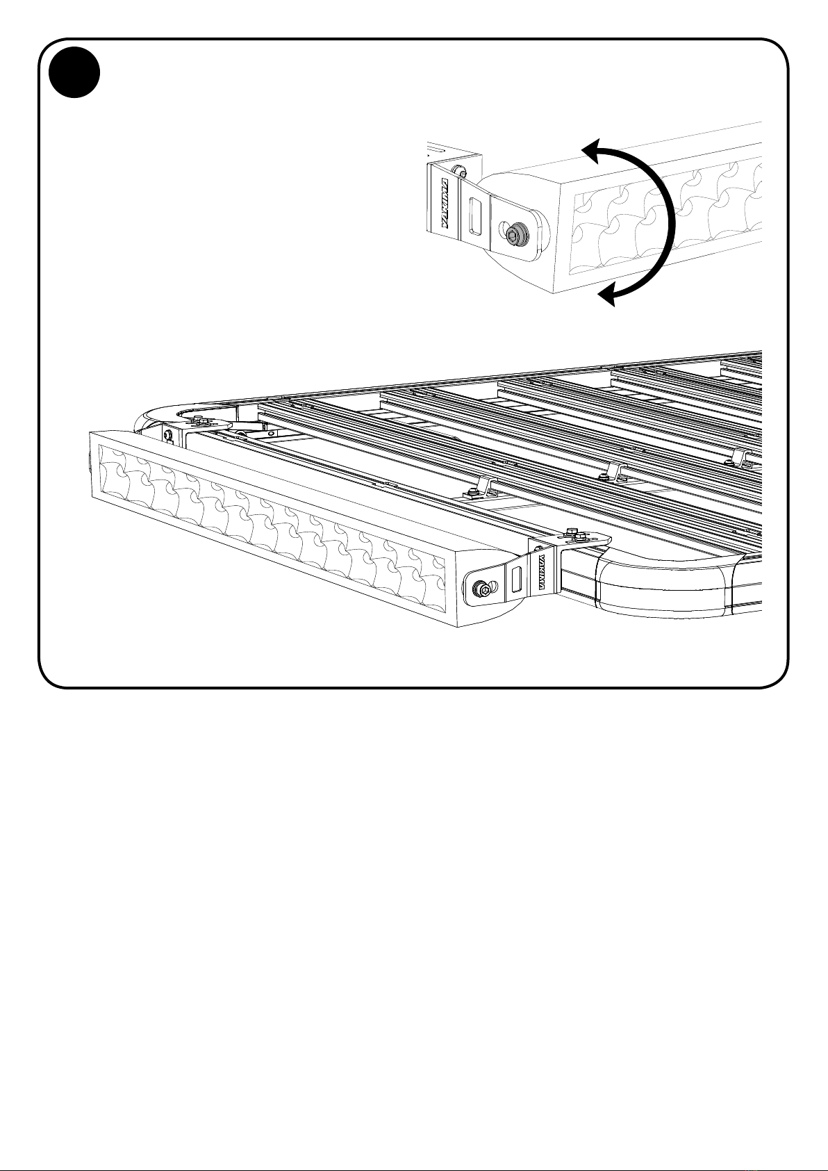
ATTACH BRACKET ASSEMBLIES TO
LIGHT BAR
Attach the 2 Bracket assemblies
to your light bar using the screws
supplied within your light bar kit
and the appropriate sized washers
supplied in the LOCKN’LOAD Light
Bracket Kit.
Finger tighten screws to allow the
light bar to be adjusted once mounted.
6
NOTE - M8 Light Bar hardware is shown in this example.
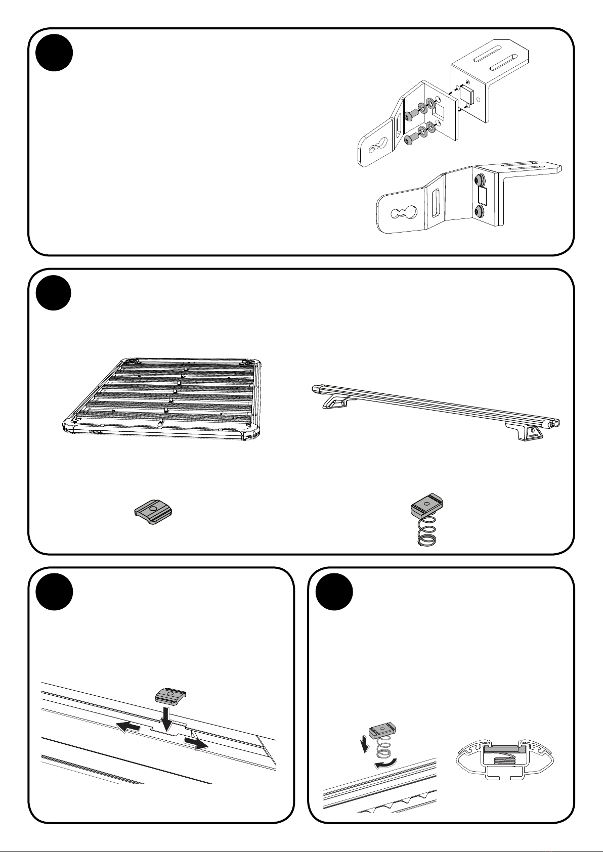
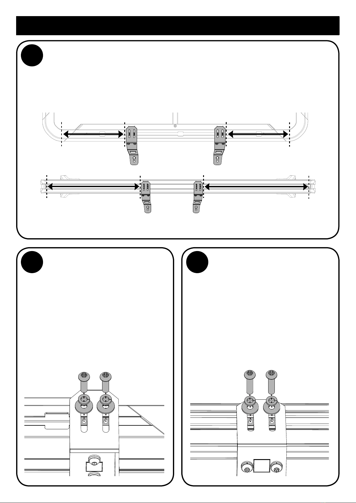
CENTRE LIGHT BAR AND ADJUST SLOT/SPRING NUTS
Position and centre light bar and Bracket assembly on Platform or Crossbar by ensuring there
is an equal distance from the Platform corners or Crossbar ends as shown. Adjust Slot/Spring
nuts in the channel so that they align with the openings in Bracket Bases. The Torx Key can be
used to assist Nut movement within the channel.
NOTE - Ensure that position of light bar, or multiple light bars, complies with relevant state legislation.
7
==
==
NOTE - Screws supplied
within your light bar kit
LIGHT BAR HARDWARE
Determine whether your light bar
uses M6, M8, M10 or M12 screws.
The overlapping holes as shown
from left to right are for M10/12,
M6 and M8.
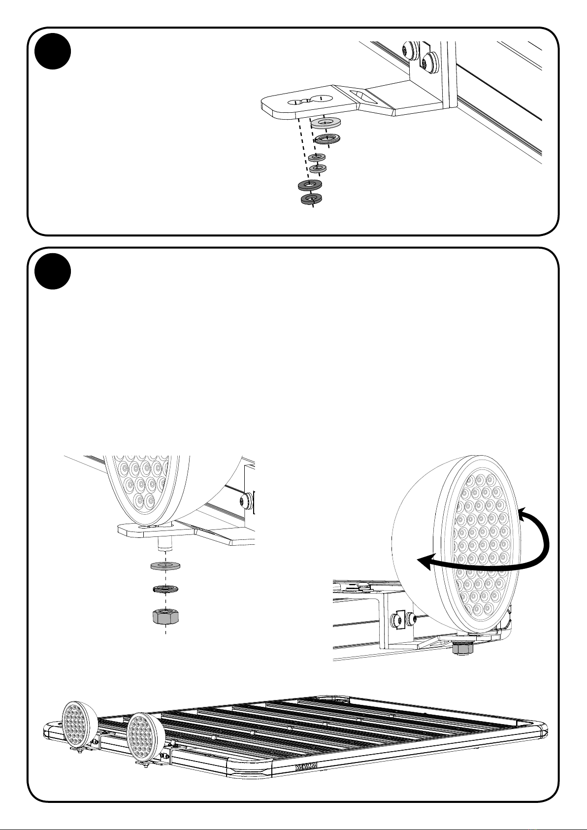
Washers and Spring Washers
are provided in the LOCKN’LOAD
Light Bracket Kit to prevent
damage to your Brackets.
5
M10/12
M6
M8