Yale SHAW-BOX YK Series Installation guide

P/N: C11746308
YK™, SK™, Y80 &
800 Series
CRANE KIT ASSEMBLY INSTRUCTION MANUAL
TRSG ASSEMBLY
INSTRUCTION MANUAL
www.columbusmckinnon.com
P/N: C11746308 REV. AB June 2022

P/N: C11746308 REV. AB June 2022
2
TABLE OF CONTENTS
1) SAFETY PRECAUTIONS .......................................................................................................................4
IMPORTANT INFORMATION AND WARNINGS......................................................................................... 5
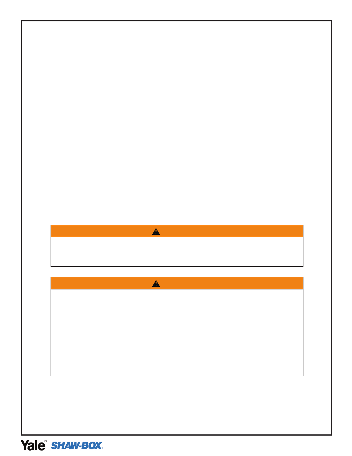
2) FABRICATION OF GIRDER(S) FOR BRIDGE BEAM WITH CAPPING CHANNEL .............................8
STEP 1: CUT GIRDER AND C-CHANNEL (AS REQUIRED)..................................................................... 9
STEP 2: CHECK CAMBER (AS REQUIRED).............................................................................................. 9
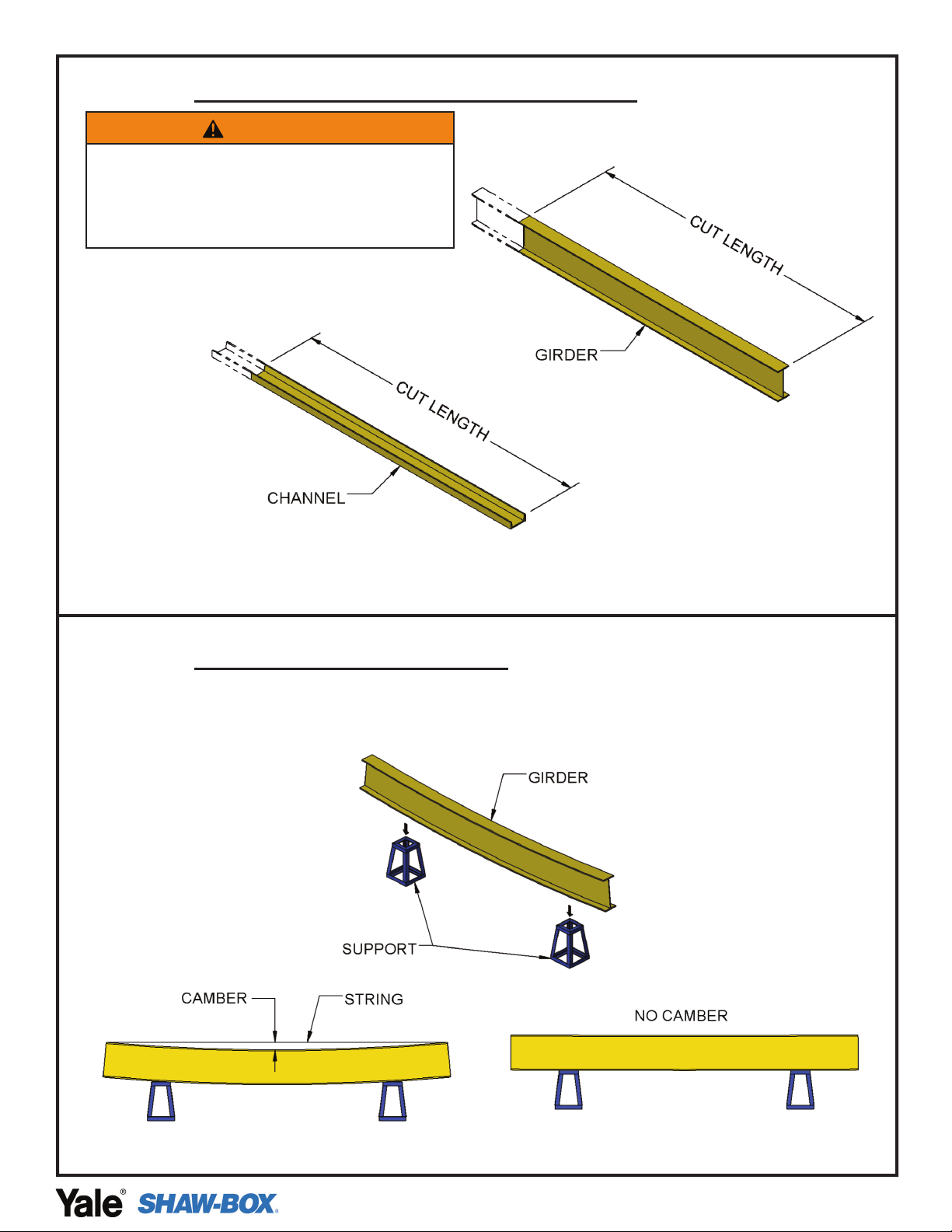
STEP 3: GIRDER AND C-CHANNEL WELDING AT END (AS REQUIRED)............................................. 10
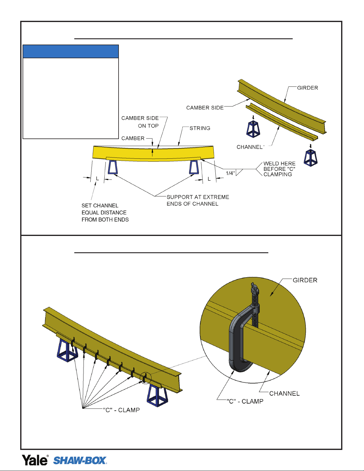
STEP 4: CLAMPING GIRDER AND C-CHANNEL (AS REQUIRED)......................................................... 10
STEP 5: GIRDER AND C-CHANNEL WELDING (AS REQUIRED)........................................................... 11
STEP 6: CHECK CAMBER AFTER WELDING (AS REQUIRED).............................................................. 11
3) ASSEMBLING BRIDGE GIRDER TO END TRUCKS (SINGLE GIRDER).............................................12
3.A) TRSG END TRUCK TYPES.................................................................................................................. 13
3.B) INTEGRAL-AXLE TUBE-FRAME END TRUCK .................................................................................. 14
3.C) FIXED AXLE END TRUCK.................................................................................................................... 15
3.D) CHANNEL TYPE END TRUCK............................................................................................................. 16
3.E) ROTATING AXLE TOP RUNNING END TRUCK................................................................................. 17
STEP 1: NOTCHING GIRDER AT ENDS (AS REQUIRED) ....................................................................... 18
STEP 2: MOUNTING GIRDER ON SUPPORT (AS REQUIRED).............................................................. 18
STEP 3: LOCATE & ALIGN END TRUCKS.................................................................................................. 19
STEP 4: POSITION END TRUCKS.............................................................................................................. 19
STEP 5: CHECK SQUARENESS BETWEEN END TRUCKS.................................................................... 20
STEP 6: CHECK SPAN DISTANCE BETWEEN END TRUCKS ................................................................ 20
STEP 7: WELDING END TRUCKS WITH GIRDER.................................................................................... 21
STEP 8: TRIA METRIC END TRUCK DRIVE INSTALLATION .................................................................. 22
STEP 8A: TRFA END TRUCK A4 DRIVE INSTALLATION ......................................................................... 23
STEP 8B: TRFC END TRUCK DRIVE INSTALLATION.............................................................................. 24
STEP 8C: TRRA END TRUCK DRIVE INSTALLATION.............................................................................. 25
STEP 9: BRIDGE BOLTED PLATE END CONNECTION SINGLE GIRDER ............................................ 26
4) END STOPS & TROLLEY STOPS..........................................................................................................27
4.A) END STOP ASSEMBLY......................................................................................................................... 28
4.B TROLLEY STOPS SUPPLIED BY CUSTOMER................................................................................... 28
5) MOUNTING HOIST ON GIRDER............................................................................................................29
YK/SK HOIST INSTALLATION ..................................................................................................................... 30
STEP 1: PREPARATION FOR MOUNTING HOIST ON GIRDER ............................................................. 30
STEP 2: MOUNTING HOIST ON GIRDER .................................................................................................. 31
Y80/800 HOIST INSTALLATION................................................................................................................... 32
STEP 1: PREPARATION FOR MOUNTING HOIST ON GIRDER ............................................................. 32
STEP 2: MOUNTING HOIST ON GIRDER .................................................................................................. 33

P/N: C11746308 REV. AB June 2022
3
6) FESTOON SYSTEM INSTALLATION.....................................................................................................34
6.A) PLAN VIEW ............................................................................................................................................ 35
STEP 1: CLAMPING CROSS ARM & CONTROL BOX SUPPORT RAILS ............................................... 36
STEP 2: SPACING FOR CROSS ARMS/SUPPORT RAILS ...................................................................... 36
STEP 3: C-RAIL MOUNTING........................................................................................................................ 37
STEP 4: C-RAIL JOINT ASSEMBLY ............................................................................................................ 38
STEP 5: MOUNTING BRIDGE PANEL ........................................................................................................ 39
STEP 6: END STOP ASSEMBLY.................................................................................................................. 40
STEP 7: HOIST CABLE ASSEMBLY............................................................................................................ 41
STEP 8: CONTROL PENDANT CABLE ASSEMBLY.................................................................................. 42
YK/SK TOW ARM........................................................................................................................................... 43
STEP 9: TOW ARM KIT PREPARATION ..................................................................................................... 43
TOW ARM ADJUSTMENTS.......................................................................................................................... 43
Y80/800 TOW ARM ........................................................................................................................................ 44
STEP 9: TOW ARM KIT PREPARATION ..................................................................................................... 44
TOW ARM ADJUSTMENTS.......................................................................................................................... 44
STEP 10: TOW ARM KIT INSTALLATION – YK/SK .................................................................................... 45
STEP 10: TOW ARM KIT INSTALLATION – Y80/800.................................................................................. 46
STEP 11: CABLE TRAY INSTALLATION ..................................................................................................... 47
STEP 12: PLACING FESTOON CABLES ON CABLE TRAY..................................................................... 48
STEP 13: FESTOON CABLE CONNECTION ............................................................................................. 49
STEP 14: PUSH-BUTTON PENDANT ASSEMBLY .................................................................................... 50
STEP 15: BRIDGE MOTOR CABLE CONNECTION .................................................................................. 51
STEP 16: BRIDGE TOW ARM INSTALLATION........................................................................................... 52
STEP 17: BRIDGE TRAVEL LIMIT SWITCH INSTALLATION ................................................................... 53
STEP 18: FESTOON RUNWAY CHECKING ............................................................................................... 54
STEP 19: ADDING CABLE TIES .................................................................................................................. 54
7) RADIO CONTROL & HORN INSTALLATION FOR FESTOON SYSTEM..............................................55
STEP 1: CROSS ARM & BRACKET INSTALLATION FOR RADIO CONTROL........................................ 56
STEP 2: RADIO CONTROL SYSTEM INSTALLATION .............................................................................. 57
STEP 3: HORN INSTALLATION (INTERNAL/EXTERNAL)........................................................................ 58
8) WARRANTY ............................................................................................................................................60
TABLE OF CONTENTS

P/N: C11746308 REV. AB June 2022
4
CHAPTER 1
SAFETY PRECAUTIONS
Safety Alert Symbols
Throughout this manual are steps and procedures that can prevent hazardous situations; the
following symbols are used to identify the degree or level of hazard seriousness.
DANGER, WARNING, CAUTION AND NOTICE
Symbol Description
Danger
Indicates an imminently hazardous situation
which, if not avoided, will result in death or
serious injury and property damage.
Warning
Indicates an imminently hazardous situation
which, if not avoided, could result in death
or serious injury and property damage.
Caution
Indicates a potentially hazardous situation
which, if not avoided, may result in minor or
moderate injury and property damage.
Notice
Notifies people of installation, operation or
maintenance information which is important
but not directly hazard-related.
WARNING
Failure to read and comply with any of the limitations noted in this
manual can result in serious bodily injury or death, and/or property
damage.

P/N: C11746308 REV. AB June 2022
5
IMPORTANT INFORMATION AND WARNINGS
Failure to read and comply with any of the limitations noted herein can result in serious
bodily injury or death, and/or property damage.
Equipment described in this manual is not designed for and should not be used for lifting,
supporting, or transporting humans.
To ensure the good working order and reliable operation of your hoist, strictly adhere to the
requirements for that installation provided in this manual.
Strictly adhere to the requirements for safe operation to prevent danger to personnel and
damage to the electric hoist.
Repairs shall be completed only with parts supplied by the manufacturer.
The connection of the bridge panel power cable to the crane runway power supply shall be
completed only by a qualified electrician.
Assembly and commissioning of the crane system shall only be done by qualified persons,
authorized by CMCO.
Modifications to upgrade, re-rate, or otherwise alter this equipment shall be authorized only
by the original equipment manufacturer or qualified professional engineer.
Equipment described in this manual may be used in the design and manufacture of cranes.
Additional equipment or devices may be required for the crane to comply with applicable
crane design and safety standards. The crane designer, crane manufacturer, or user is
responsible for finishing these additional items for compliance. Refer ASME B30.2 Safety
Standard for Top-Running Double-Girder Cranes. If a below-the-hook lifting device or sling
is used with a hoist, refer to ASME B30.9, Safety Standard for Slings, or ASME B30.20,
Safety Standard for Below-the-Hook Lifting Devices.
Hoists and cranes used to handle hot molten material may require additional equipment or
devices. Refer to ANSI Z241.2, Safety Requirements for Melting and Pouring of Metals in
the Metalcasting Industry.
The hoists are not designed to operate in a chemically aggressive and explosive
environment.
Working in or near exposed energized electrical equipment presents the danger of electric shock.
WARNING
Before installing, removing inspecting, or performing any maintenance on a hoist, the main switch
shall be de-energized. Lock and tag the main switch in the de-energized position in accordance
with ANSI Z244.1.
Follow other maintenance procedures outlined in this manual and applicable ASME B30 volumes.
Additional WARNINGS are listed in various portions of this manual. Personnel shall read and
follow these WARNINGS. Failure to read and comply with these WARNINGS as well as other
instructions or any limitations noted in this manual and applicable ASME B30 volumes could result
in serious bodily injury or death, and/or property damage.

P/N: C11746308 REV. AB June 2022
6
Read and observe the instructions and warnings contained in this manual. Read and
observe any instructions and warning tags attached to the hoist.
Check for any damage to the components during shipment. If any damage has occurred,
place a claim with the carrier. DO NOT install damaged components.
Check wire rope for damage and proper spooling on the drum. Be sure rope is properly
seated in drum grooves and sheaves. Make sure both of the rope ends are tightly secured.
After each rope replacement, as well as after repair and reassembling of the electric hoist,
check the phasing and direction of operation. Verify the hook position of all limit switches
per the hoist manual.
Be certain that power supply to bridge control panel has the same voltage, frequency, and
phase that are specified on the bridge control panel nameplate.
Before performing maintenance and repair activities, make sure that there is no load on
the hook, the power supply switch is turned offand unauthorized switching is prevented
through lockout and tagout procedures.
Check the load hook for cracks and deformations and verify proper operation of the release
latch.
The bridge frame shall not be considered electrically grounded through the end truck
wheels and its respective tracks. A separate runway bonding conductor must be provided.
WARNING
Hazardous voltages are present in the control enclosure, other electrical components, and
connections between these components.
Before performing any mechanical or electrical maintenance on the equipment, disconnect the
main switch supplying power to the equipment and implement lockout/tagout procedure. Refer to
ANSI Z244.1, personnel protection - lockout/tagout of energy sources.
DO NOT operate the equipment without control enclosure cover or covers in place.
Only trained and competent personnel should inspect and repair this equipment.

P/N: C11746308 REV. AB June 2022
7
If hoist has a trolley, check that the crane bridge beam is level, straight, and clean. Check
that trolley stops are installed, or install trolley stops, at the open end or ends of the beam
to prevent the trolley from traveling offthe beam. Trolley stops that engage trolley wheels
are not recommended. Check that trolley stops will prevent overhanging parts of the hoist
and trolley from interfering with other equipment beyond the ends of the beam.
Daily, before starting work, check the operation of the brake and the limit switches.
Do not use a limit switch as an operational limit in any case.
Do not leave the lifted load out of sight.
Do not exceed the rated capacity.
Do not lift loads at an angle and do not drag them.
Do not try to detach firmly fixed loads (e.g., frozen to the ground).
Do not change or modify the electric diagram. Do not use the pushbuttons and limit
switches for other purposes but those indicated.
Equipment covered herein is not designed or suitable as a power source for lifting or
lowering persons. Lifting and moving of loads over personnel is not allowed.
Warning signs and barriers shall be utilized on the floor beneath the crane or area where
the hoist will be installed.
WARNING
Damage to the hoist, a droped load, and injury may result if limit switches fail due to improper use.
Under normal operating conditions,stop hoist travel before engaging limit switches. Limit switches
are safety devices and should not be used as normal opertating control.
WARNING
Only qualied personnel with proper supervision shall install the hoist on the monorail and
perform the nal pre-operation inspection.
Before installing, removing, inspecting, or performing any maintenance on a hoist, the main switch
shall be de-energized. Lock and tag the main switch in the de-energized position in accordance
with ANSI Z244.1.
Follow other maintenance procedures outlined in the manual and applicable ASME B30 volumes.
Additional WARNINGS are listed in various portions of this manual. Personnel shall read and
follow these WARNINGS. Failure to read and comply with these WARNINGS as well as other
instructions or any limitations noted in this manual and applicable ASME B30 volumes could
result in serious bodily injury or death, and/or property damage.

P/N: C11746308 REV. AB June 2022
8
CHAPTER 2
FABRICATION OF GIRDER(S)
FOR BRIDGE BEAM WITH
CAPPING CHANNEL
(AS REQUIRED)

P/N: C11746308 REV. AB June 2022
9
STEP 1: CUT GIRDER AND C-CHANNEL (AS REQUIRED)
Check your configuration to see if a capping channel is required.
CUT LENGTH TO BE DETERMINED BY SPAN LENGTH
STEP 2: CHECK CAMBER (AS REQUIRED)
WARNING
Selection of structural steel beams must be veried
by qualied engineer. IT IS IMPORTANT THAT
ALL INSTRUCTIONS BE FOLLOWED AND THAT
COMPONENT APPLICATION LIMITS NOT BE
EXCEEDED.

P/N: C11746308 REV. AB June 2022
10
STEP 3: GIRDER AND C-CHANNEL WELDING AT END (AS REQUIRED)
ALL WELD IS TO BE AWS CLASS E-70XX OR EQUIVALENT
STEP 4: CLAMPING GIRDER AND C-CHANNEL (AS REQUIRED)
NOTICE
Assembly of beam and channel requires
welding. IT IS EXTREMELY IMPORTANT TO
THE SAFETY OF THIS BRIDGE THAT THIS
WELDING BE DONE BY A COMPETENT
WELL-TRAINED WELDER. It is our strong
recommendation that the welder used in
this construction be qualied as prescribed
by the American Welding Society (AWS)
Structural Welding Code-Steel D1.1-2008
and Specication for Welding Industrial
and Mill Cranes D14.1-2005.

P/N: C11746308 REV. AB June 2022
11
STEP 5: GIRDER AND C-CHANNEL WELDING (AS REQUIRED)
ALL WELD IS TO BE AWS CLASS E-70XX OR EQUIVALENT
STEP 6: CHECK CAMBER AFTER WELDING (AS REQUIRED)
CAMBER ≤{DEFLECTION OF GIRDER AT DEAD LOAD
+ 1/2 * DEFLECTION OF GIRDER AT LIVE LOAD}
NOTICE
Assembly of beam and channel requires
welding. IT IS EXTREMELY IMPORTANT TO
THE SAFETY OF THIS BRIDGE THAT THIS
WELDING BE DONE BY A COMPETENT
WELL-TRAINED WELDER. It is our strong
recommendation that the welder used in
this construction be qualied as prescribed
by the American Welding Society (AWS)
Structural Welding Code-Steel D1.1-2008
and Specication for Welding Industrial
and Mill Cranes D14.1-2005.

P/N: C11746308 REV. AB June 2022
12
CHAPTER 3
ASSEMBLING BRIDGE GIRDER
TO END TRUCKS
(SINGLE GIRDER)

P/N: C11746308 REV. AB June 2022
13
3.A) TRSG END TRUCK TYPES

P/N: C11746308 REV. AB June 2022
14
3.B) INTEGRAL-AXLE TUBE-FRAME END TRUCK
WARNING
Alterations or modications of equipment and use
of non-factory repair parts can lead to dangerous
operation and injury.
TO AVOID INJURY:
DO NOT alter or modify equipment.
DO NOT use equipment to lift, support or otherwise
transport people.
DO NOT suspend unattended loads over people.

P/N: C11746308 REV. AB June 2022
15
3.C) FIXED AXLE END TRUCK

P/N: C11746308 REV. AB June 2022
16
3.D) CHANNEL TYPE END TRUCK

P/N: C11746308 REV. AB June 2022
17
3.E) ROTATING AXLE TOP RUNNING END TRUCK

P/N: C11746308 REV. AB June 2022
18
STEP 1: NOTCHING GIRDER AT ENDS (AS REQUIRED)
*REFER TO STEP 7 FOR VALUES OF F & G
NOTCH CUT AT BOTH ENDS OF THE GIRDER,
USING TORCH OR PLASMA BURNER AND
SMOOTHE THE BURNED AREA BY GRINDING.
A COPED GIRDER CONNECTION IS SHOWN FOR ILLUSTRATION PURPOSES ONLY.
ACTUAL GIRDER CONNECTION ARRANGEMENT MAY DIFFER BY APPLICATION.
STEP 2: MOUNTING GIRDER ON SUPPORT (AS REQUIRED)
Check your configuration to see if a capping channel is required.
A COPED GIRDER CONNECTION IS SHOWN FOR ILLUSTRATION PURPOSES ONLY.
ACTUAL GIRDER CONNECTION ARRANGEMENT MAY DIFFER BY APPLICATION.

P/N: C11746308 REV. AB June 2022
19
STEP 3: LOCATE & ALIGN END TRUCKS
A COPED GIRDER CONNECTION IS SHOWN FOR ILLUSTRATION PURPOSES ONLY.
ACTUAL GIRDER CONNECTION ARRANGEMENT MAY DIFFER BY APPLICATION.
STEP 4: POSITION END TRUCKS
A COPED GIRDER CONNECTION IS SHOWN FOR ILLUSTRATION PURPOSES ONLY.
ACTUAL GIRDER CONNECTION ARRANGEMENT MAY DIFFER BY APPLICATION.

P/N: C11746308 REV. AB June 2022
20
STEP 5: CHECK SQUARENESS BETWEEN END TRUCKS
FOR SQUARENESS BETWEEN END TRUCKS: (D1~D2) ≤1/16"
D1 & D2 - DIAGONAL MEASUREMENTS
STEP 6: CHECK SPAN DISTANCE BETWEEN END TRUCKS
NOTICE
The crane builder and user are responsible for marking
the crane and also for checking for compliance with all
local, state and national codes.
Other manuals for SHAW-BOX YK Series
1
This manual suits for next models
3
Table of contents
Other Yale Construction Equipment manuals
Popular Construction Equipment manuals by other brands

EZG
EZG Grip Hog PM-1AIR owner's manual

Hailo
Hailo Fast & Lock 7 quick start guide

HEIN-WERNER AUTOMOTIVE
HEIN-WERNER AUTOMOTIVE HW93809 Operating instructions & parts manual

Strend Pro
Strend Pro TCT0504C instruction manual

STEELTEC
STEELTEC XWS009 instruction manual

Fayat Group
Fayat Group DYNAPAC F80W Service book