Yamaha AS2000BL User manual

■CONTENTS
TO SERVICE PERSONNEL .......................................... 2
FRONT PANEL .............................................................. 2
REAR PANELS .......................................................... 3–5
REMOTE CONTROL PANELS ...................................... 6
SPECIFICATIONS / 参考仕様 .......................................... 7
INTERNAL VIEW ........................................................... 8
SERVICE PRECAUTIONS/
サービス時の注意事項 .................................................... 9
DISASSEMBLY PROCEDURES /分解手順 ............. 9–18
AMP ADJUSTMENT /アンプ部調整 ....................... 19–20
UPDATING FIRMWARE/
ファームウェアの書き込み..................................... 21–27
SELF-DIAGNOSTIC FUNCTION/
ダイアグ(自己診断機能) ..................................... 28–30
IC DATA ................................................................. 31–34
PIN CONNECTION DIAGRAMS ............................ 35–36
BLOCK DIAGRAM ....................................................... 37
PRINTED CIRCUIT BOARDS................................ 38–58
SCHEMATIC DIAGRAMS ...................................... 59–66
REPLACEMENT PARTS LIST .............................. 67–87
REMOTE CONTROL.............................................. 88–89
101077
SERVICE MANUAL
STEREO AMPLIFIER
2008 All rights reserved.
This manual is copyrighted by YAMAHA and may not be copied or
redistributed either in print or electronically without permission.
P.O.Box 1, Hamamatsu, Japan
'08.01
IMPORTANT NOTICE
This manual has been provided for the use of authorized YAMAHA Retailers and their service personnel.
It has been assumed that basic service procedures inherent to the industry, and more specifically YAMAHA Products, are already
known and understood by the users, and have therefore not been restated.
WARNING: Failure to follow appropriate service and safety procedures when servicing this product may result in personal
injury, destruction of expensive components, and failure of the product to perform as specified. For these reasons,
we advise all YAMAHA product owners that any service required should be performed by an authorized
YAMAHA Retailer or the appointed service representative.
IMPORTANT: The presentation or sale of this manual to any individual or firm does not constitute authorization, certification or
recognition of any applicable technical capabilities, or establish a principle-agent relationship of any form.
The data provided is believed to be accurate and applicable to the unit(s) indicated on the cover. The research, engineering, and
service departments of YAMAHA are continually striving to improve YAMAHA products. Modifications are, therefore, inevitable
and specifications are subject to change without notice or obligation to retrofit. Should any discrepancy appear to exist, please
contact the distributor's Service Division.
WARNING: Static discharges can destroy expensive components. Discharge any static electricity your body may have
accumulated by grounding yourself to the ground buss in the unit (heavy gauge black wires connect to this buss).
IMPORTANT: Turn the unit OFF during disassembly and part replacement. Recheck all work before you apply power to the unit.
A-S2000
A-S2000

2
A-S2000
A-S2000
■FRONT PANEL
A-S2000 (U, C, R, T, K, A, B, G, L, J models)
WALL
OUTLET
EQUIPMENT
UNDER TEST
AC LEAKAGE
TESTER OR
EQUIVALENT
INSULATING
TABLE
WARNING: CHEMICAL CONTENT NOTICE!
This product contains chemicals known to the State of California to cause cancer, or birth defects or other reproductive
harm.
DO NOT PLACE SOLDER, ELECTRICAL/ELECTRONIC OR PLASTIC COMPONENTS IN YOUR MOUTH FOR ANY
REASON WHAT SO EVER!
Avoid prolonged, unprotected contact between solder and your skin! When soldering, do not inhale solder fumes or expose
eyes to solder/flux vapor!
If you come in contact with solder or components located inside the enclosure of this product, wash your hands before
handling food.
1. Critical Components Information
Components having special characteristics are marked s
and must be replaced with parts having specifications equal
to those originally installed.
2. Leakage Current Measurement (For 120V Models Only)
When service has been completed, it is imperative to verify
that all exposed conductive surfaces are properly insulated
from supply circuits.
●Meter impedance should be equivalent to 1500 ohms shunted
by 0.15µF.
●Leakage current must not exceed 0.5mA.
●Be sure to test for leakage with the AC plug in both polarities.
本機に搭載されているすべての基板およびハンダ付けによる接合
部は無鉛ハンダでハンダ付けされています。
無鉛ハンダにはいくつかの種類がありますが、修理時には下記の
ような無鉛ハンダの使用を推奨します。
・ Sn+Ag+Cu(錫+銀+銅)
・ Sn+Cu(錫+銅)
・ Sn+Zn+Bi(錫+亜鉛+ビスマス)
注意:
無鉛ハンダの融点温度は通常の鉛入りハンダに比べ30〜40℃
程度高くなっていますので、それぞれのハンダに合ったハンダ
ごてをご使用ください。
All of the P.C.B.s installed in this unit and solder joints are
soldered using the lead free solder.
Among some types of lead free solder currently available,
it is recommended to use one of the following types for the
repair work.
• Sn + Ag + Cu (tin + silver + copper)
• Sn + Cu (tin + copper)
• Sn + Zn + Bi (tin + zinc + bismuth)
Caution:
As the melting point temperature of the lead free solder is
about 30°C to 40°C (50°F to 70°F) higher than that of the lead
solder, be sure to use a soldering iron suitable to each solder.
About lead free solder / 無鉛ハンダについて
■TO SERVICE PERSONNEL

3
A-S2000
A-S2000
■REAR PANELS
A-S2000 (U, C models)
A-S2000 (R model)
A-S2000 (T model)

4
A-S2000
A-S2000
A-S2000 (B model)
A-S2000 (K model)
A-S2000 (A model)

5
A-S2000
A-S2000
A-S2000 (G model)
A-S2000 (L model)
A-S2000 (J model)

6
A-S2000
A-S2000
■REMOTE CONTROL PANELS
RAS21
(U, C, R, T, A, B, G, L models)
RAS22
(K, J models)

7
A-S2000
A-S2000
■Audio Section / オーディオ部
Minimum RMS Output Power (Power Amp. Section) /
定格出力(パワーアンプ部)(20 Hz to 20 kHz, 0.02 % THD)
8 ohms ......................................................................... 90 W + 90 W
4 ohms .................................................................... 150 W + 150 W
Dynamic Power / ダイナミックパワー(IHF)
8/6/4/2 ohms ..................................................... 105/135/190/220 W
Maximum Output Power [B, G models] (1 kHz, 0.7 % THD, 4 ohms)
............................................................................................... 160 W
Maximum Useful Output Power (JEITA) [R, T, K, L models]
(1 kHz, 10 % THD)
8 ohms ................................................................................... 120 W
4 ohms ................................................................................... 190 W
Dynamic Headroom / ダイナミックヘッドルーム
8 ohms ................................................................................. 0.67 dB
IEC Output Power [B, G models] (1 kHz, 0.02 % THD)
8 ohms ..................................................................................... 95 W
4 ohms ................................................................................... 155 W
Damping Factor / ダンピングファクター (1 kHz, 8 ohms)
.................................................................................................... 160
Maximum Input Signal / 最大許容入力
CD, etc. .................................................................................... 2.8 V
PHONO (1 kHz) MM ........................................................... 120 mV
MC ................................................................ 7 mV
Frequency Response / 周波数特性
CD, etc.
Flat position, 5 Hz to 100 kHz .................................... +0 / -3.0 dB
Flat position, 20 Hz to 20 kHz .................................... +0 / -0.3 dB
RIAA Equalization Deviation / RIAA偏差 (20 Hz to 20 kHz)
PHONO MM ........................................................................ ±0.5 dB
MC ......................................................................... ±0.5 dB
Total Harmonic Distortion / 全高調波歪率 (20 Hz to 20 kHz)
CD BAL to SP OUT (90 W, 8 ohms) .................................... 0.01 %
CD, etc. to SP OUT (90 W, 8 ohms) .................................. 0.015 %
PHONO MM (2 V, to REC) ................................................ 0.005 %
MC (2 V, to REC) ................................................... 0.05 %
Intermodulation Distortion / 混変調歪率 (Rated output, 8 ohms)
CD, etc. to SP OUT .............................................................. 0.02 %
Signal to Noise Ratio / 信号対雑音比 (IHF-A Network) (Input shorted)
CD, etc. (150 mV) ................................................................... 98 dB
PHONO MM (5 mV) ............................................................... 93 dB
MC (500 µV) ............................................................. 85 dB
Residual Noise / 残留ノイズ (IHF-A Network)
FRONT L/R SP OUT .................................................. 33 µV or less
■Control Section / コントロール部
Input Sensitivity/Input Impedance / 入力感度/入力インピーダンス
CD, etc. .............................................................. 150 mV/47 k-ohms
PHONO MM ....................................................... 2.5 mV/47 k-ohms
MC ........................................................... 100 µV/50 ohms
MAIN IN .................................................................... 1 V/47 k-ohms
Output Level/ Output Impedance / 入力電圧/インピーダンス
REC OUT .......................................................... 150 mV/1.5 k ohms
PRE OUT ................................................................. 1 V/1.5 k ohms
Headphone Rated Output / ヘッドホン出力/インピーダンス
1 kHz, 0.2 % THD, 32 ohms ................................................. 30 mW
Channel Separation / チャンネルセパレーション (1 kHz/10 kHz)
CD, etc. (5.1 k-ohms terminated) ......................... 74/54 dB or more
PHONO (Input shorted, Vol: -30 dB) MM ........... 90/77 dB or more
MC ............ 66/77 dB or more
Tone Control Characteristics / トーンコントロール特性
BASS
Boost/Cut (50 Hz) ................................................................ ±9 dB
Turnover frequency ............................................................ 350 Hz
TREBLE
Boost/Cut (20 Hz) ................................................................ ±9 dB
Turnover frequency ........................................................... 3.5 kHz
Audio Muting / ミュート
............................................................................... -20 dB (approx.)
■SPECIFICATIONS / 参考仕様
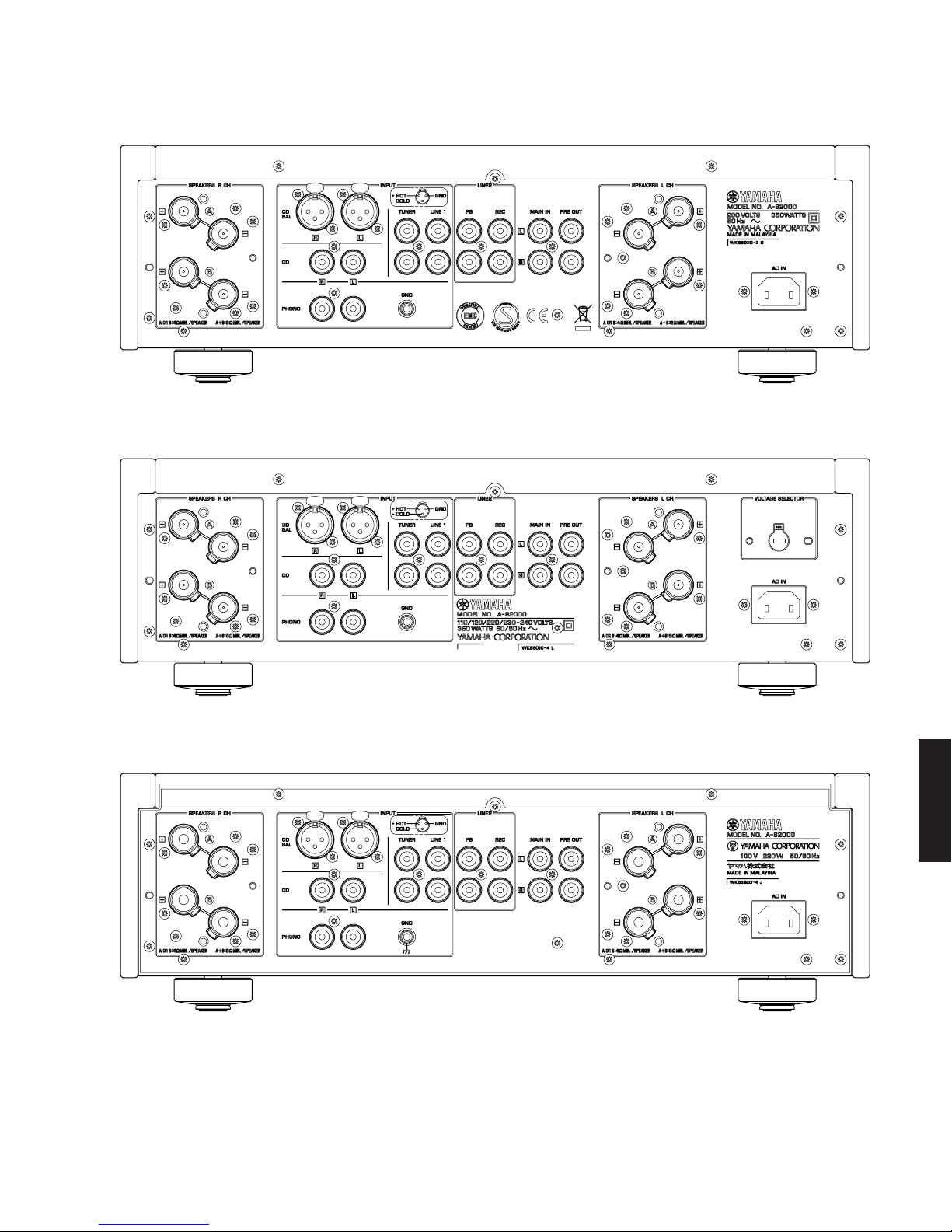
U .......... U.S.A. model
C .......... Canadian model
R .......... General model
T .......... Chinese model
K .......... Korean model
A .......... Australian model
B .......... British model
G .......... European model
L .......... Singapore model
J ........... Japanese model
■General / 総合
Power Supply /電源電圧
U, C models ........................................................... AC 120 V, 60 Hz
R, L models .......................... AC 110/120/220/230-240 V, 50/60 Hz
T model .................................................................. AC 220 V, 50 Hz
K model .................................................................. AC 220 V, 60 Hz
A model .................................................................. AC 240 V, 50 Hz
B, G models ........................................................... AC 230 V, 50 Hz
J model ............................................................ AC 100 V, 50/60 Hz
Power Consumption/ 消費電力
U, C, R, T, K, A, B, G, L models ........................................... 350 W
J model .................................................................................. 220 W
Idling Power Consumption/ アイドル時消費電力
................................................................................................. 80 W
Off-state Power Consumption/ パワーOFF時消費電力
................................................................................................... 0 W
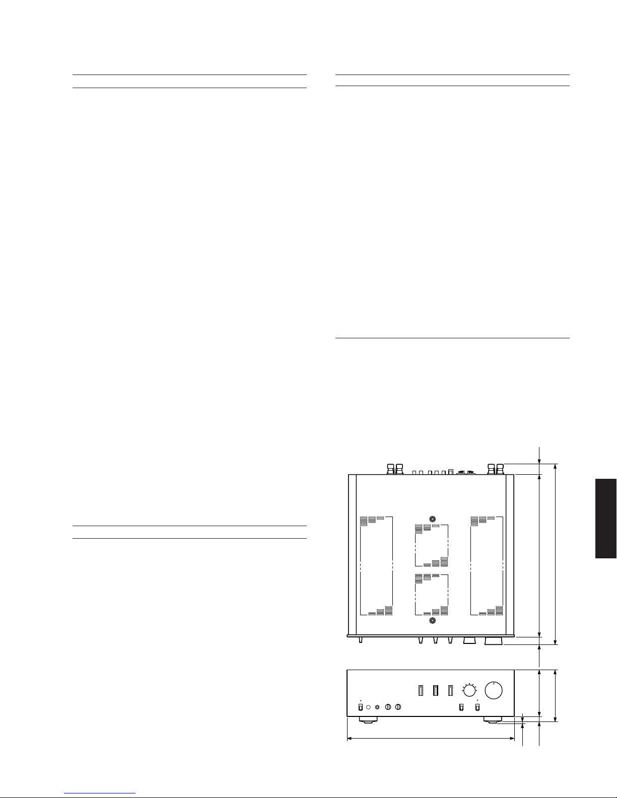
Dimensions (W x H x D) /寸法(幅×高さ×奥行き)
.......................... 435 x 137 x 465 mm (17-1/8” x 5-3/8” x 18-5/16”)
Weight /質量
............................................................................... 22.7 kg (50 lbs.)
Finish/仕上げ
Black color ................................ U, C, R, T, K, A, B, G, L, J models
Silver color ................................ U, C, R, T, K, A, B, G, L, J models
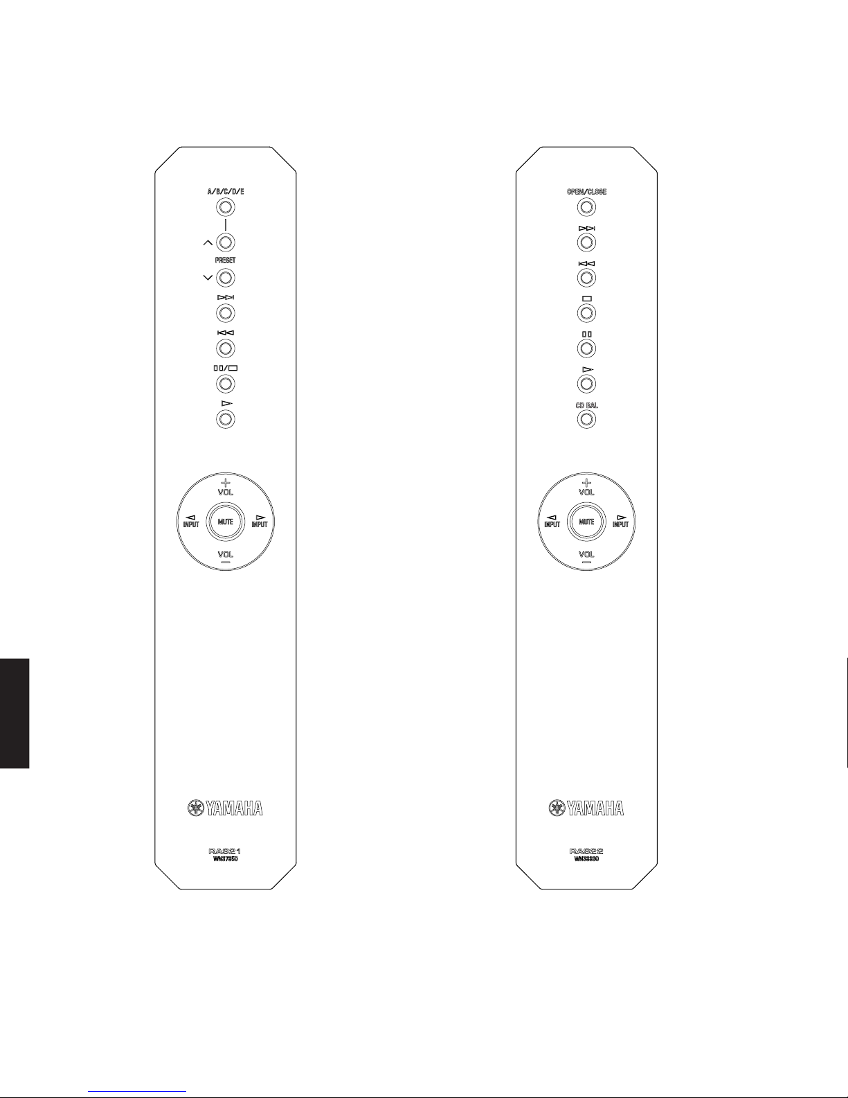
Accessories /付属品
Remote control x 1, Battery (R6, AA, UM-3) x 2, Power cable (2 m) x 1
* Specifications are subject to change without notice due to product
improvements.
※ 参考仕様および外観は予告なく変更されることがあります。
435 (17-1/8")
137 (5-3/8") 465 (18-5/16")
418 (16-7/16") 25
(1")
22
(7/8")
16
(5/8")
3
(1/8") 121 (4-3/4")
•DIMENSIONS / 寸法図
Unit: mm (inch)
単位:mm(インチ)

8
A-S2000
A-S2000
■INTERNAL VIEW
1FRONT (14) P.C.B. (R, L models)
2FUNCTION (3) P.C.B.
3FRONT (13) P.C.B.
4MAIN (2) P.C.B.
5FUNCTION (2) P.C.B.
6POWER TRANSFORMER
7MAIN (3) P.C.B.
8MAIN (1) P.C.B.
9FRONT (12) P.C.B.
0FRONT (11) P.C.B.
AFRONT (9) P.C.B.
BFRONT (2) P.C.B.
CFRONT (1) P.C.B.
DFRONT (3) P.C.B.
EFRONT (6) P.C.B.
FFRONT (5) P.C.B.
GFRONT (4) P.C.B.
HFRONT (7) P.C.B.
IFRONT (8) P.C.B.
JBALANCE P.C.B.
KFUNCTION (1) P.C.B.
LFRONT (10) P.C.B.
23 5 7 96
GFE
0
A
J K L
IH
BC D
14 8
Top View
Front View
Rear View

A-S2000
9
■DISASSEMBLY PROCEDURES / 分解手順
(Remove parts in the order as numbered.)
Disconnect the power cable from the AC outlet.
1. Removal of Panel Side L/R
a. Remove 2 screws (1), 2 coned disc spring L and 2
washers side. (Fig. 1)
b. Lift the panel side L a little and release 3 hooks. Then
remove the panel side L. (Fig. 1)
c. Remove 2 screws (2), 2 coned disc spring L and 2
washers side. (Fig. 1)
d. Lift the panel side R a little and release 3 hooks. Then
remove the panel side R. (Fig. 1)
2. Removal of Top Cover
a. Remove 7 screws (3), 2 screws (4) and 2 screws
(5). (Fig. 1)
b. Remove the top cover. (Fig. 1)
3. Removal of Front Panel
*Prepare a hexagonal wrench (2 mm) for removal of
knob unit.
a. Loosen lock set screw to remove the knob VOL unit.
(Fig. 1)
b. Loosen lock set screw to remove the knob SEL unit.
(Fig. 1)
c. Loosen each lock set screw to remove 3 knob TC unit.
(Fig. 1)
d. Remove 8 screws (6). (Fig. 1)
e. Set the “POWER ON/OFF” switch to the ON position.
f. Set the “PHONO MM/MC” switch to the MM position.
g. Remove the front panel forward gradually using care
not to cause damage the switches. (Fig. 1)
(番号順に部品を取り外してください。)
AC電源コンセントから、電源コードを抜いてください。
1. パネルサイドL/Rの外し方
a. 1のネジ2本を外し、サラバネL2個とワッシャーサイド
2個を外します。(Fig.1)
b. パネルサイドLを少し持ち上げ、3ヶ所のフックを外
し、パネルサイドLを取り外します。(Fig.1)
c. 2のネジ2本を外し、サラバネL2個とワッシャーサイド
2個を外します。(Fig.1)
d. パネルサイドRを少し持ち上げ、3ヶ所のフックを外
し、パネルサイドRを取り外します。(Fig.1)
2. トップカバーの外し方
a. 3ネジ7本、4のネジ2本、5のネジ2本を外します。
(Fig.1)
b. トップカバーを取り外します。(Fig.1)
3. フロントパネルの外し方
※ ノブユニットを取り外す場合、6角レンチ(2mm)を
準備します。
a. 止めネジを緩め、ノブVOLユニットを取り外します。
(Fig.1)
b. 止めネジを緩め、ノブSELユニットを取り外します。
(Fig.1)
c. 止めネジを緩め、ノブTCユニット3個を取り外しま
す。(Fig.1)
d. 6のネジ8本を外します。(Fig.1)
e. POWERON/OFFスイッチをONにします。
f. PHONOMM/MCスイッチをMMにします。
g. 各スイッチに傷がつかないよう注意してフロントパネ
ルを前方へゆっくり取り外します。(Fig.1)
Panel side L
パネルサイドL
Panel side R
パネルサイドR
Washer side
ワッシャーサイド
Washer side
ワッシャーサイド
Coned disc spring L
サラバネL
Coned disc spring L
サラバネL
Front panel
フロントパネル
Top cover
トップカバー
6
6
3
1
3
4
5
2
Hook
フック
Hook
フック
POWER ON / OFF switch
POWERON/OFFスイッチ
PHONO ON / OFF switch
PHONOON/OFFスイッチ
Hook
フック
Knob VOL unit
ノブVOLユニット
Hexagonal wrench
6角レンチ
Knob SEL unit
ノブSELユニット
Knob TC unit
ノブTCユニット
2mm
Lock set screw
止めネジ
Fig. 1
■SERVICE PRECAUTIONS / サービス時の注意事項
安全対策
・ この製品の内部には高電圧部分があり危険です。修理の
際は、絶縁性の手袋を使用するなどの安全対策を行って
ください。
・ 下記箇所には電源をOFFにした後も電荷が残り、高電圧
が維持されており危険です。
修理作業前に放電用抵抗(5kΩ/10W)を下記箇所の端子
間に接続して放電してください。放電所用時間は約30
秒間です。
1. MAIN(3)P.C.B.のC308
2. MAIN(3)P.C.B.のC309
3. MAIN(3)P.C.B.のC335
4. MAIN(3)P.C.B.のC336
PRINTEDCIRCUITBOARDS:MAIN(3)P.C.B.を参
照してください。
Safety measures
•Some internal parts in this product contain high volt-
ages and are dangerous. Be sure to take safety mea-
sures during servicing, such as wearing insulating
gloves.
•Note that positions indicated below are dangerous even
after the power is turned off because an electric charge
remains and a high voltage continues to exist there.
Before starting any repair work, perform discharge by
connecting a discharge resistor (5k-ohms/10W) be-
tween terminals at following positions. The time re-
quired for discharging is about 30 seconds.
1. C308 on MAIN (3) P.C.B..
2. C309 on MAIN (3) P.C.B..
3. C335 on MAIN (3) P.C.B..
4. C336 on MAIN (3) P.C.B..
Refer to “PRINTED CIRCUIT BOARDS: MAIN (3) P.C.B.”.
*When installing the knob unit, it is necessary to position
them as specified. (Refer to “When installing the knob
unit”.)
※ ノブユニットを取り付ける場合、決められた位置に合
わせる必要があります。(「ノブユニットを取り付ける
場合」参照)

A-S2000
10
● ノブVOLユニットを取り付ける場合:
a. VOLUME(VR501)を左いっぱいに回します。
(Fig.2)
b. ノブVOLユニットのスリットをVOLUMEMIN
の位置に合わせ、取り付けます。(Fig.2)
※ このとき、まだ止めネジは締めません。
c. フロントパネルからノブVOLユニットまで0.5〜
0.75mm程度隙間をあけます。(Fig.2)
d. VOLUME(VR501)のカット位置に止めネジ位置
を合わせ、止めネジを締めます。(Fig.2)
e. 取り付け後、次の動作を確認します。
・ ノブVOLユニットを左右に回し、フロント
パネルに擦っていないか?
・ ノブVOLユニットを右いっぱいに回し、ノ
ブVOLユニットのスリットがVOLUME
MAXの位置に合うか?
・ ノブVOLユニットを左いっぱいに回し、ノ
ブVOLユニットのスリットがVOLUME
MINの位置に合うか?
● ノブSELユニットを取り付ける場合:
a. INPUT(SW501)のカット位置が上になるよう回
します。(Fig.2)
b. ノブSELユニットの止めネジ位置を上にして取
り付けます。(Fig.2)
※ このとき、止めネジは締めません。
c. フロントパネルからノブSELユニットまで0.5〜
0.75mm程度隙間をあけます。(Fig.2)
d. INPUT(SW501)のカット位置に止めネジ位置を
合わせ、止めネジを締めます。(Fig.2)
e. 取り付け後、次の動作を確認します。
・ ノブSELユニットを左右に回し、フロントパ
ネルに擦っていないか?
● ノブTCユニットを取り付ける場合:
※ BASS、TREBLE、BALANCEの取り付け方法
はすべて同じです。
例としてBALANCEの取り付け方法を記載しま
す。
a. BALANCE(VR504)を左右に回し、中央の位置
に合わせます。(Fig.2)
※ 左右に回すと、中央の位置で一度止まりま
す。
b. ノブTCユニットのスリットをBALANCE中央の
位置に合わせ、取り付けます。(Fig.2)
※ このとき、まだ止めネジは締めません。
c. フロントパネルからノブTCユニットまで0.5〜
0.75mm程度隙間をあけます。(Fig.2)
d. ノブTCユニットの止めネジを締めます。(Fig.2)
●When installing the knob VOL unit:
a. Turn the VOLUME (VR501) counterclockwise
fully. (Fig. 2)
b. Match the slit in the knob VOL unit with the
“VOLUME MIN”position and install it in that
state. (Fig. 2)
*At this time, do not tighten the lock set screw.
c. Keep about 0.5 mm to 0.75 mm clearance from
the front panel to knob VOL unit. (Fig. 2)
d. Match the lock set screw position with the cut in
VOLUME (VR501) and tighten the lock set screw.
e. After installation, perform following checks.
•Turn the knob VOL unit both directions to
check that it does not rub against the front
panel.
•Turn the knob VOL unit clockwise fully and
check that the slit in it matches with the
“VOLUME MAX”position.
•Turn the knob VOL unit counterclockwise
fully and check that the slit in it matches with
the “VOLUME MIN”position.
●When installing the knob SEL unit:
a. Turn the INPUT (SW501) so that the cut in it
comes at the top. (Fig. 2)
b. Install the knob SEL unit with its lock set screw
positioned at the top. (Fig. 2)
*At this time, do not tighten the lock set screw.
c. Keep about 0.5 mm to 0.75 mm clearance from
the front panel to knob SEL unit. (Fig. 2)
d. Match the lock set screw position with the cut in
INPUT (SW501) and tighten the lock set screw.
e. After installation, perform following checks.
•Turn the knob SEL unit in both directions to
check that it does not rub against the front
panel.
●When installing the knob TC unit
*Use the same installation procedure for BASS,
TREBLE and BALANCE.
Described here is installation of BALANCE as
an example.
a. Turn the BALANCE (VR504) in both directions
and set it to the center position. (Fig. 2)
*VR504 stops at the center position when it is
turned in both directions.
b. Match the slit in the knob TC unit with the center
position of BALANCE and install it in that state.
(Fig. 2)
*At this time, do not tighten the lock set screw.
c. Keep about 0.5 mm to 0.75 mm clearance from
the front panel to knob TC unit. (Fig. 2)
d. Tighten the lock set screw of the knob TC unit.
(Fig. 2)
Knob VOL unit
ノブVOLユニット
Slit
スリット
Cut
カット位置
Lock set screw
止めネジ
Lock set screw
止めネジ
Lock set screw
止めネジ
Center position of BALANCE
BALANCE中央
VR501
SW501
VR504
VOLUME MIN VOLUME MAX
Knob SEL unit
ノブSELユニット
Knob TC unit
ノブTCユニット
Front panel
フロントパネル
0.5–0.75mm
Fig. 2
e. 取り付け後、次の動作を確認します。
・ ノブTCユニットを左右に回し、フロントパ
ネルに擦っていないか?
・ ノブTCユニットを左いっぱいに回し、ノブ
TCユニットのスリットがBALANCELの
位置に合うか?
・ ノブTCユニットを右いっぱいに回し、ノブ
TCユニットのスリットがBALANCERの
位置に合うか?
e. After installation, perform following checks.
•Turn the knob TC unit in both directions to
check that it does not rub against the front
panel.
•Turn the knob TC unit counterclockwise
fully and check that the slit in it matches with
the “BALANCE L”position.
•Turn the knob TC unit clockwise fully and
check that the slit in it matches with the
“BALANCE R”position.

11
A-S2000
A-S2000
Fig. 3
4. フロントフレームASSYの外し方
a. 7のネジ4本を外し、フレームトップを取り外します。
(Fig.3)
b. 8のネジ8本を外します。(Fig.3)
c. CB501、CB504、CB517、CB519、CB521、SW1-2
を外します。(Fig.3)
d. フロントフレームASSYを取り外します。(Fig.3)
4. Removal of Front Frame Ass’y
a. Remove 4 screws (7) to remove the frame top. (Fig. 3)
b. Remove 8 screws (8). (Fig. 3)
c. Remove CB501, CB504, CB517, CB519, CB521 and
SW1-2. (Fig. 3)
d. Remove the front frame ass’y. (Fig. 3)
7
8
8
8
7
Frame top
トップフレーム
Front frame ass'y
フロントフレームASSY
Front frame ass'y
フロントフレームASSY
CB504
CB517CB519 CB521
SW1
SW2
CB501

12
A-S2000
A-S2000
P.C.B.をチェックをする場合には:
・ 本機の上にゴムシートと布を敷き、その上にP.C.B.を
裏返しに置いてチェックします。(Fig.4)
・ 外したケーブル(コネクター)をすべて接続します。
・ 本機ではフロントフレームASSYのアースがシャーシ
に接続されています。フロントフレームASSYを
シャーシより取り外した場合は、アース線等でシャー
シに接続してください。(Fig.4)
When checking the P.C.B.:
•Put the rubber sheet and cloth over this unit. Then
place the P.C.B.s upside down on the cloth and
check it. (Fig. 4)
•Reconnect all cables (connectors) that have been
disconnected.
•In this unit, the ground of the front frame ass’y is con-
nected to the chassis. When the front frame ass’y is
removed from the chassis, connect the ground point
to the chassis, using a ground lead wire or the like.
(Fig. 4)
Fig. 4
Rubber sheet and cloth
ゴムシートと布
Ground lead
アース線
Front frame ass'y
フロントフレームASSY

13
A-S2000
A-S2000
A
A0
9
9
9
B
B
C
C
D
D
D
D
D
E
E
CB52
CB21
CB22
CB24
CB26
CB73
CB76
CB74
CB72
CB84
CB71
CB405
CB34
CB406
Frame side L
フレームサイドL
AMP unit R
アンプユニットR
AMP unit L
アンプユニットL
POWER unit
パワーユニット
Bottom cover
ボトムカバー
Leg
レッグ
Leg
レッグ
CB54
CB64
CB25
Fig. 5
5. アンプユニットL/Rの外し方
a. 9のネジ8本、0のネジ2本を外します。(Fig.5)
b. フレームサイドLを取り外します。(Fig.5)
c. Aのネジ4本を外します。(Fig.5)
d. CB71-74、CB76、CB84、CB406を外します。(Fig.5)
e. アンプユニットLをヒートシンクと一緒に取り外しま
す。
f. Bのネジ4本、Cのネジ4本を外します。(Fig.5)
g. CB52、CB54、CB64、CB405を外します。(Fig.5)
h. アンプユニットRをヒートシンクと一緒に取り外しま
す。
5. Removal of Amplifier Unit
a. Remove 8 screws (9) and 2 screws (0). (Fig. 5)
b. Remove the frame side L. (Fig. 5)
c. Remove 4 screws (A). (Fig. 5)
d. Remove CB71-74, CB76, CB84 and CB406. (Fig. 5)
e. Remove the amplifier unit L together with the heat sink.
f. Remove 4 screws (B) and 4 screws (C). (Fig. 5)
g. Remove CB52, CB54, CB64 and CB405. (Fig. 5)
h. Remove the amplifier unit R together with the heat
sink.
6. パワーユニットの外し方
a. レッグ4個を外します。(Fig.5)
b. Dのネジ18本を外します。(Fig.5)
c. ボトムカバーを取り外します。(Fig.5)
d. Eのネジ4本を外します。(Fig.5)
e. CB21-22、CB24-26、CB34を外します。(Fig.5)
f. パワーユニットを取り外します。(Fig.5)
6. Removal of Power Unit
a. Remove 4 legs. (Fig. 5)
b. Remove 18 screws (D). (Fig. 5)
c. Remove the bottom cover. (Fig. 5)
d. Remove 4 screws (E). (Fig. 5)
e. Remove CB21-22, CB24-26 and CB34. (Fig. 5)
f. Remove the power unit. (Fig. 5)

14
A-S2000
A-S2000
● パワーユニットを取り付ける場合:
パワーユニットを取り付ける場合、ネジの先端で底
面のケーブルにキズ等付けないよう十分注意してく
ださい。(Fig.6)
●When installing the power unit:
When installing the power unit, be very careful not
to cause any damage to the cable at the bottom
with the end of the screw. (Fig. 6)
Cable
ケーブル Front side
Rear side
End of the screw
ネジの先端
Bottom view
Fig. 6

15
A-S2000
A-S2000
When checking the P.C.B.:
•Remove frame panels L/R.
•Put the rubber sheet and cloth over this unit. Then
place the P.C.B. slantingly on the cloth and check it.
(Fig. 7)
•Reconnect all cables (connectors) that have been
disconnected.
•In this unit, the ground of the amplifier unit L/R is
connected to the chassis. When the amplifier unit L/R
is removed from the chassis, connect the ground
point to the chassis, using a ground lead wire or the
like. (Fig. 7)
•It is also possible to check the amplifier unit L/R from
the bottom. (Fig. 7)
Rubber sheet and cloth
ゴムシートと布
Cloth
布
Ground lead
アース線
Ground lead
アース線 AMP unit R
アンプユニットR
AMP unit R
アンプユニットR
AMP unit L
アンプユニットL
AMP unit L
アンプユニットL
Fig. 7
P.C.B.をチェックをする場合には:
・ フレームパネルL/Rは外します。
・ 本機の上にゴムシートと布を敷き、その上にP.C.B.を
斜めに置いてチェックします。(Fig.7)
・ 外したケーブル(コネクター)をすべて接続します。
・ 本機ではアンプユニットL/Rのアースがシャーシに接
続されています。アンプユニットL/Rをシャーシより
取り外した場合は、アース線等でシャーシに接続して
ください。(Fig.7)
・ アンプユニットL/Rは底面からチェックすることもで
きます。(Fig.7)

16
A-S2000
A-S2000
7. FUNCTION(2)P.C.B.の外し方
a. Fのネジ4本、Gのネジ1本を外します。(Fig.8)
b. CB401-404を外します。(Fig.8)
c. TRコネクターを外します。(Fig.8)
d. 底面のケーブル(W4004)を外します。(Fig.9)
e. FUNCTION(2)P.C.B.を取り外します。(Fig.8)
7. Removal of FUNCITON (2) P.C.B.
a. Remove 4 screws (F) and a screw (G). (Fig. 8)
b. Remove CB401-404. (Fig. 8)
c. Remove the connector TR. (Fig. 8)
d. Disconnect the cable (W4004) from the bottom. (Fig. 9)
e. Remove FUNCTION (2) P.C.B.. (Fig. 8)
Fig. 8
N
N
HH
F
F
G
I
L
Q
R
R
O
P
J
K
M
M
CB27
CB201
CB202
CB203
CB401
CB23
CB2
CB79
CB59
CB402
CB403
CB404
Frame side R
フレームサイドR
Connector TR
TRコネクター
Solder
ハンダ
Barrier SP R
バリアSPR
Barrier SP L
バリアSPL
Speaker terminal L
スピーカーターミナルL
Speaker terminal R
スピーカーターミナルR
FUNCTION (2) P.C.B.
FUNCTION (3) P.C.B.
BALANCE P.C.B.
FRONT (11) P.C.B.
FRONT (13) P.C.B.
FRONT (12) P.C.B.
Solder
ハンダ

17
A-S2000
A-S2000
Bottom view
W4004
Fig. 9
8. Removal of BALANCE P.C.B.
a. Remove 3 screws (H) and 4 screws (I). (Fig. 8)
b. Remove CB59 and CB201-203. (Fig. 8)
c. Remove BALANCE P.C.B.. (Fig. 8)
9. Removal of Speaker Terminal L/R
a. Remove 2 screws (J) and 2 screws (K). (Fig. 8)
b. Remove CB2, CB23 and CB79. (Fig. 8)
c. Remove FUNCTION (3) P.C.B.. (Fig. 8)
d. Remove 2 push rivets (L) and then remove the barrier
SP L. (Fig. 8)
e. Remove 5 screws (M). (Fig. 8)
f. Remove the speaker terminal L together with the
P.C.B.. (Fig. 8)
g. Unsolder the P.C.B. to separate the speaker terminal
L. (Fig. 8)
h. Remove 2 screws (N). (Fig. 8)
i. Remove CB27. (Fig. 8)
j. Remove FUNCTION (11) P.C.B.. (Fig. 8)
k. Remove 4 screws (O) and 3 screws (P). (Fig. 8)
l. Remove frame side R. (Fig. 8)
m. Remove 2 push rivets (Q) and then remove the barrier
SP R. (Fig. 8)
n. Remove 5 screws (R). (Fig. 8)
o. Remove the speaker terminal R together with the
P.C.B.. (Fig. 8)
p. Unsolder the P.C.B. to separate the speaker terminal
R. (Fig. 8)
8. BALANCEP.C.B.の外し方
a. Hのネジ3本、Iのネジ4本を外します。(Fig.8)
b. CB59、CB201-203を外します。(Fig.8)
c. BALANCEP.C.B.を取り外します。(Fig.8)
9. スピーカーターミナルL/Rの外し方
a. Jのネジ2本、Kのネジ2本を外します。(Fig.8)
b. CB2、CB23、CB79を外します。(Fig.8)
c. FUNCTION(3)P.C.B.を取り外します。(Fig.8)
d. Lのプッシュリベット2個を外し、バリアSPLを取り外
します。(Fig.8)
e. Mのネジ5本を外します。(Fig.8)
f. スピーカターミナルLをP.C.B.と一緒に取り外します。
(Fig.8)
g. P.C.B.のハンダを取り除き、スピーカーターミナルLを
取り外します。(Fig.8)
h. Nのネジ2本を外します。(Fig.8)
i. CB27を外します。(Fig.8)
j. FRONT(11)P.C.B.を取り外します。(Fig.8)
k. Oのネジ4本、Pのネジ3本を外します。(Fig.8)
l. フレームサイドRを取り外します。(Fig.8)
m. Qのプッシュリベット2個を外し、バリアSPRを取り
外します。(Fig.8)
n. Rのネジ5本を外します。(Fig.8)
o. スピーカターミナルRをP.C.B.と一緒に取り外します。
(Fig.8)
p. P.C.B.のハンダを取り除き、スピーカーターミナルRを
取り外します。(Fig.8)

18
A-S2000
A-S2000
U
S
S
T
S
S
CB305
Support PRE R
サポートPRER
Support PRE L
サポートPREL
FUNCTION (1) P.C.B.
FRONT (10) P.C.B.
10. FUNCTION(1)P.C.B.およびFRONT(10)P.C.B.
の外し方
a. Sのネジ9本、Tのネジ1本、Uのネジ2本を外しま
す。(Fig.10)
b. CB305を外します。(Fig.10)
c. 底面のケーブル(W3004)を外します。(Fig.11)
d. FUNCTION(1)P.C.B.およびFRONT(10)P.C.B.をサ
ポートPREL/Rと一緒に取り外します。(Fig.10)
10. Removal of FUNCTION (1) P.C.B. and FRONT
(10) P.C.B.
a. Remove 9 screws (S), a screw (T), and 2 screws (U).
(Fig. 10)
b. Remove CB305. (Fig. 10)
c. Remove the cable (W3004) from the bottom. (Fig. 11)
d. Remove FUNCTION (1) P.C.B and FRONT (10) P.C.B.
together with the support PRE L/R. (Fig. 10)
Fig. 10
Fig. 11
Bottom view
W3004

A-S2000
19
(Side A)
MAIN (1) P.C.B.
CB55
VR101
R ch
CB75
DC +4.0 to +8.0 mV
VR201
Front side
(Side A)
MAIN (2) P.C.B.
L ch
10
0 minute
+4.0 to +8.0 mV
DC voltage / DC電圧
11020
mV
VR201
CB75
DC +4.0 to +8.0 mV
MAIN (2) P.C.B. L ch
CB55
DC +4.0 to +8.0 mV
MAIN (1) P.C.B. R ch
VR101
Fig. 1
■AMP ADJUSTMENT / アンプ部調整
● アイドリング調整●Idling Adjustment
条件
・ 電源を入れてから20分経過後に調整を始めます。
・ 無入力信号
・ 無負荷
アイドリング調整
CB75(Lch)/CB55(Rch)のDC電圧が+4.0〜+8.0mV
になるように、VR201(Lch)/VR101(Rch)を調整し
ます。(Fig.1)
Condition
• Start adjustment 20 minutes or more after the
power is turned on.
• Non loaded condition
Idling Adjustment
Adjust VR201 (Lch)/VR101 (Rch) so that the DC volt-
age of CB75 (Lch)/CB55 (Rch) becomes +4.0 to
+8.0mV. (Fig. 1)
Precaution for handling measuring instrument
The ground side of the measuring instrument to be con-
nected to the speaker terminal of this unit must be kept in
floating condition because this unit is equipped with the
floating balanced power amplifier.
計測器取り扱い上の注意
本機はフローティングバランスパワーアンプを搭載して
いるので、本機のスピーカー出力端子に接続する計測器
のアース側はフローティング状態にする必要がありま
す。

A-S2000
20
● ヘッドフォンDCオフセット調整
条件
・ 電源を入れてから5秒間以上経過後に調整を始めま
す。
・ 無入力信号
・ 無負荷
DCオフセット調整
CB504のDC電圧が-2.0〜+2.0mVになるように、
VR202(Lch)/VR102(Rch)を調整します。(Fig.2)
●Headphone DC Offset Adjustment
Condition
• Start adjustment 5 sec or more after the power is
turned on.
• No input signal.
• Non loaded condition
DC offset adjustment
Adjust VR202 (Lch)/VR102 (Rch) so that the DC volt-
age of the CB504 becomes -2.0 to +2.0mV. (Fig. 2)
Fig. 2
(Side A)
MAIN (1) P.C.B.
R ch
VR102
VR102
VR202
VR202
Front side
(Side A)
MAIN (2) P.C.B.
L ch
(Side A)
FRONT (2) P.C.B.
R ch L ch
PHONES
DC -2.0 to +2.0 mV
FRONT (2) P.C.B.
L ch
R ch DC -2.0 to +2.0 mV
PHONES
R ch
MAIN (2) P.C.B.
VR102VR202
L ch
MAIN (1) P.C.B.
This manual suits for next models
1
Table of contents
Other Yamaha Amplifier manuals

Yamaha
Yamaha A-S700 - Amplifier User manual

Yamaha
Yamaha DSP-AX861SE User manual

Yamaha
Yamaha A-S3000 User manual

Yamaha
Yamaha P1150 User manual

Yamaha
Yamaha PC3000A User manual

Yamaha
Yamaha AV-50 User manual

Yamaha
Yamaha IPA8200 User manual

Yamaha
Yamaha THR30II Wireless User manual

Yamaha
Yamaha A-S700 - Amplifier User manual

Yamaha
Yamaha DSP-A2 User manual

Yamaha
Yamaha MX-1 User manual

Yamaha
Yamaha M-80 User manual

Yamaha
Yamaha A-1 User manual

Yamaha
Yamaha MX-A5200 Instruction manual

Yamaha
Yamaha C 450 User manual

Yamaha
Yamaha DSP-A595a User manual

Yamaha
Yamaha B-2 User manual

Yamaha
Yamaha B-2x User manual

Yamaha
Yamaha A-1 User manual

Yamaha
Yamaha MX-70 User manual