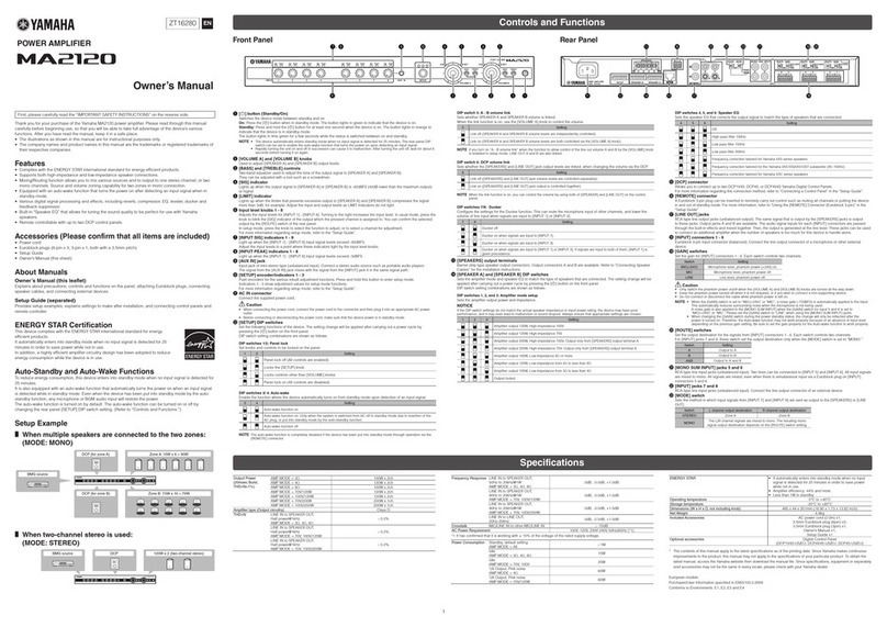
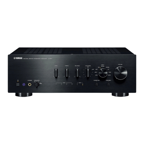
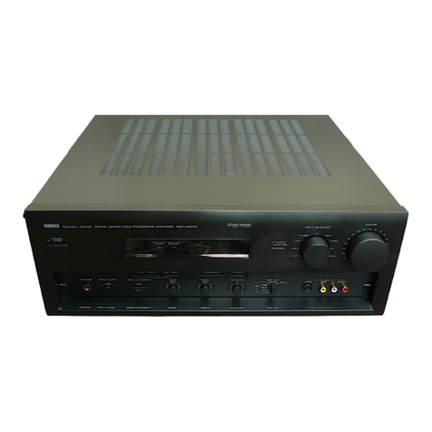
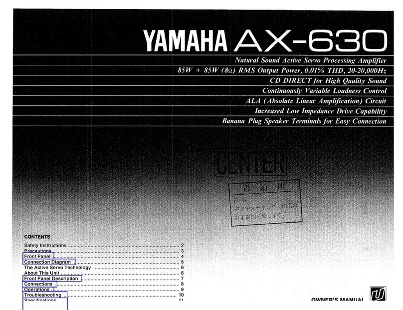
Yamaha AX-390 User manual

STEREO AMPLIFIER
A)G390
YAilAllA urunm souNo srEFEo aMpLrF EB ax-3eo
orcwEF .,",,*H'?^,.,
'.Y, r r.9, '
,;?ri<V, ,;?äq, "rli\|. ,-A;"
,{r }'. "{r )f, Jr-}'" "Yr ' )t;
Nr ++ +4 +# ,,"\
i{\
,:\\ lt,
-\\ /tt
L
IMPORTANT NOTICE
This manual has been provided for the use of authorized YAMAHA Retailers and their service personnel.
It has been assumed that basic service procedures inherent to the industry, and more specifically YAMAHA
Products, are already known and understood by the users, and have therefore not been restated.
WARNING: Failure to follow appropriate service and safety procedures when servicing this product
may result in persona) injury, destruction of expensive components, and failure of the
product to perform as specified. For these reuons, we advise all YAMAHA product owners
that any service required should be performed by an authorized YAMAHA Retailer or the
appointed service representative.
IMPORTANT: The presentation or sale of this manuai to any individual or firm does not constitute
authorization, certification or recognition of any applicable technical capabilities, or
establish a principle-agent relationship of any form.
The data provided is believed to be accurate and applicable to the unit(s) indicated on the cover. The research,
engineering, and service departments of YAMAHA are continually striving to improve YAMAHA products.
Modifications are, therefore, inevitable and specifications are subject to change without notice or obligation to
retrofit. Should any discrepancy appear to exist, please contact the distributorrs Service Division.
WARNING: Static discharges can destroy expensive components. Discharge any static electricity your
body may have accumulated by grounding yourself to the ground buss in the unit (heavy
gauge black wires connect to this buss).
IMPORTANT: Turn the unit OFF during disassembly and pan replacement. Recheck all work before you
apply power to the unit.
PIN CONNECTTON DTAGRAM ..............5
PRTNTED CIRCU|T BOARD ........... 6-11
BLOCK DIAGRAM .,,12-13
lC BLOCKS 12-13
SCHEMATIC DIAGRAM 14-15
PARTS 1rST............. .16-23
REMOTE CONTROL TRANSMITTER........-......,,.,..24
YAMAHA
EäHTf f"9§fiR§Ö]I8#
7.7K-734 En =s Printed in Japan '96.5
www.hifiengine.com

AX-390
r TO SERVICE PERSONNEL
Critical Components lnformation.
Components having special characteristlcs are marked and
must be replaced with parts having specifications equal to those
originally installed.
I REAR PANELS
V R model
V B model
V G model
WALL
OUTLET EQUIPMENT
UNDER TEST
AC LEAKAGE
TESTER OR
EQUIVALENT
INSULATING
TABLE
@@
@@
@@
E
tr E E-IdE*E EI E
8.: 3'&38€&E:
,ti:\
fll n-n ltr
ffi
@@
@@
@@
tr tr ts-EE-tsE E
8': &8€&83€:
E-E@-E ElI @tr
(9_ "
:@
(6'll a
tr
&&33€&3:
+6- -o+
^@@
@@
-@
www.hifiengine.com

AX-390
I SPECIFICATIONS
I AUDIO SECTION
Minimum RMS Output Po\ier Per Channel
Ba, 2OHz to 20kH2,0.04% THD ........... 60W
6f), 20Hz to 20kHz, 0.04% THD ...........65W
Maximum Power EIAJ
1k1z, 10% THD, 6ei (R model) ............95W
Dynamic Power Per Channel (lHF)
Bt6t4t2A .......80/95/1 15/125W
DIN Standard Output Power Per Channel
1k{z, 0.7% THD, 4e) (G model) ........... 90W
IEC Power
1kH2,0.04o/o THD, Bo (G model) .........75W
Power Band Width
8(),25W, 0.08% THD ........,.. 10Hz to 40kHz
Damping Factor
Ba, 2OHz to 20kHz I 00 or more
lnput Sensitivity/lmpedance
PHONO MM................. 2.5mVl47ka
CD etc........... ... 150mv/47ko
Maximum lnput Signal Level (1kHz, 0.04% THD)
PHONO MM ................. ...............,.....-..90mV
Output Level/lmpedance
REC OUT ......... 150mv/600o
Headphone Jack Rated Outpuvlmpedance
0.04% THD, RL = BO 0.42Vl390O
Frequency Response (20H2 lo 20kllz)
CD etc ...,....... ...........010.5d8
HIAA Equalization Deviation (20H2 to 20kHz)
PHONO MM ................. ....................0t0.5dB
Total Harmonic Distortion (20HzIo 20kHz)
PHONO MM to REC OUT (1V) ..........0.02o/o
CD etc to SP OUT (30WBO) ........... 0.02%
Signal-to-Noise Ratio (lHF-A Network)
PHONO MM (smV lnput Shorted) .......82dB
CD (Shorted), CD Driect SW ON/OFF... 108/102d8
Residual Noise (lHF-A Network)
CD Direct SW ON/OFF 50/140pV
Channel Separation (Vol. -30d8)
PHONO MM (lnput Shorted) 1kH2............................... 65dB
CD etc lkHz (lnput 5.1kO Terminated) ....................... 60dB
Tone Control Characteristics
BASS : BoosVcut ........ ......t10d8 (20H2)
Turnover Frequency .........350H2
TREBLE : BoosVcut +10d8 (20kHz)
Turnover Frequency ........ 3.5kHz
(Level related equalization)
r GENERAL
Power Supply
G, B models AC 230V, 50Hz
R model ... AC 110112012201240V,60/50H2
Power Consumption
G model .....................130W
R, B models... ............ 150W
AC Outlets
Switched x 3
G, R models 100W max. (Total)
Switched x I
B model ..,......... 100W max.
Dimensions (W x H x D) .......................435 x 146 x 308.5rnm
(17-1lB'x 5-314" x 12-118")
Weight ........ 7.3k9 (16 lbs 1 oz)
Accessories ... Remote Control Transmitter x 1
.t*;r--r*r*rr. ffi
G ....... European model
B ....... British model
R ....... General model
I INTERNAL VIEW
o
@
o
@
o
@
P.C.B. MArN (2)
P.C.B. MArN (1)
P.C.B. OPERATTON (1)
P.C.B. MArN (3)
P.C.B. OPERATTON (3)
P.C.B. OPERATION (2)
@
N
q
co
O
o
-
o
o
O
5
q
co
o
o o o.o
Units: mm (inch)
www.hifiengine.com

AX-390
I DISASSEMBLY PROGEDURES
1. Removal of Top Cover
Remove 4 screws (e ) and 3 screws (@ ) in fig. t.
2. Removal of Front Panel
a. Remove 5 knobs.
b. Remove 6 screws (@ ) in fig. t.
Top Cover
Oo
Front
Panel
Fig. 1
I ADJUSTMENTS
o Confirmation of idling current.
After Power is turned on.
Confirm that the voltages across R137 (L ch),
R138 (R ch) are between 0.1-3mV in Fig. 3.
lf they exceed 3.1mV, open (cut off) R131 (L
ch) and R132 (R ch), and reconfirm voltage is
between 0.1-3mV.
R137, R138
(Remove parts in the order as numbered.)
3. Checking and Parts Replacement of P.C.B. MAIN (1)
a. Disconnect the power cord from the AC outlet.
b. Remove 3 screws ( @ ) tixing the Speaker terminal
and Heat Sink in Fig. 2.
c. Remove 3 screws (@ ) fixing the Main Unit in Fig. 3.
d. Detach connector terminal (C8104) in Fig. 3.
e. Operating checks can be taken by shorting between
following test points in Fig. 3.
Short Point
TPl01 and TP102
TPt03 and TP104
TP105 and TP106
f. Place the Main Unit on its side as shown in Fig. 4.
g. Connect the power cord and turn ON the POWER
switch.
o
§
,a
@
p
o
E
t-ri- ),.
{.-
to,
'rbt,
(0c)tou-
@p@.@ .ffi.
P. C. B. MArN (2)
P. C. B. MA|N (1)
I\IAIN UNIT
www.hifiengine.com

I p-COM DATA
1C401 : LC66304A
4bit p-COM
AX-390
INfi
ll.JT2
sr1
so1
SeKi
PIN1. POUTl
P00
P01
P02
P03
P10
P11
P12
Pl3
st0/P20
so0/P21
scxupzz
rNTO/P23
tr'rf tlPaO
POUTO/P31
POUIlIP32
nörolpss
P40
P41
TEST
VSS
osc 1
PE1/TRB
PEO/TBA RES
VDD TEST
PD3/CMP3
PDZ|CMP2 osc 1
PO1/CMP1 osc2
PDOiCMPO
pCgiVREFl HoLD
PC2iVFEFO
P6s/PrN'1
P62lSCK1
P61/SO1
P60/Sl1 rRA
pssltNT2 IHB
P52 CMPO
P51 cMpl
P50 cMF2
P43 cMP3
P42
HIS
POUT O
sro
so0
so(o
INTO
No. Port uo Name Function
1P00 N. C.
2P01 IPSEL Model Detect
3P02 oMUTE Mute
4P03 N. C.
5P10 oPRY Power Relav
6 P11 oVM+ lMrin votr*" uP
/ Down
7P12 oVM_
8P13 N. C.
Isl0/P20 o40528 ) tnout setector
't0 so0/P21 o40524
't1 scxolpzz N. C.
12 lNT0/P23
13 tNTl/P30 REM Remote Control
14 POUTO/P31 orMONl Tape 1 Monitor
15 POUTl/P32 oTMON2 Taoe 2 Monitor
16 HOLD/P33 HOLD Hold
17 P40 oPLED Power LED
18 P41 nSTBY Standby LED
't9 TEST TEST ) u*o
20 VSS VSS
21 OSCl OSCl Clock (4MHz)
No. Port vo Name Function
22 osc2 oosc2 Clock (4MHz)
23 RES RES Reset lnput
24 P42 )*'
25 P43
26 P50 oPHLED
lnput LED drive
27 P51 oCDLED
28 P52 oTULED
29 P53/tNT2 oAUXLED
30 P60/Sr 1UT1 LED
31 P61/SO1 oT2LED
32 P6215CKl- PRT Protection
33 P63/PtN1 PSW Power Switch
34 PC2lVREFO oD1 )xev oioit
35 PC3/VREF1 oD2
36 PDO/CMPO K1
]-", lnput
37 PD1/CMP1 K2
38 PD2ICMP2 K3
39 PD3/CMP3 K4
40 VDD VDD +5V
41 PEO/TRA IG/NOTG Market Detect (H : B, G / L : R)
42 PEl/TRB Model Detect
www.hifiengine.com

AX-390
I TEST POINT WAVEFORMS
Point C point @
(Pin 21 of 1C401) (CH1 :Pin 23 of tC401 ) V:2Vldiv (CH1)
V:5Vidiv H:O.1psec/div [ClZ:Collector ol Q403_J V:SV/div (CH2)
DCrange 1:lprobe H:O.5sec/div
DCrange 1:1probe
(This wavelorm is not available by pushing lhe power switch ON and OFF.)
SFr Pl I DuS
t)
I
\
ru ?U SA PI Fa" 5
With lhe POWER ON, dis- Disconnect the
connect the A/C power cord. power cord lrom the
Reconnect the A/C power AC ouilet.
cord and the above wave-
,orms will start.
CHl
I PIN CONNEGTION DIAGRAM
a lCs
NJM2O68L.D LB1 641 TC4053BP
TC4052BP 1C66304A
o Diodes a Transistors
2SA933S (Q, R)
2SC1740S (R, S)
2SC3330 (S,T)
,4 2S41708 (S,T)
2SC44B8 (S,T)
2SA893A (D,E)
2SC1815 (Y)
2SC1890A (D,E)
2SC2229 (O,Y)
2SC2240 (GR,BL)
2SC2878 (A, B) 2SA1695 (O,P,Y)
2SC4466 (O,P,Y)
2SC4468 (O,P,Y)
2SC4495
W
1SS133 HZS4C2TD
1SS27OA HZSsC2TD
1SR139-100 HZS6C2TD
HZS9B2TD
HZS12A2rD
HZS152TD
www.hifiengine.com

I PRINTED CIRCUIT BOARD (Foil side) ,/ y- l-.tr (/ \t -yßJl)
a Semiconductor Locations
P.C.B.OPERAT|ON(1)
REC
I our
TAPE 2
L TAPE
PB
REC
T our
TAPE 1
L TAPE
PB
AUX
TUNER
PHONO
iel N0. ocalion
tc301 C5
rc 302 AE
rc 303 D4
tc 304 D4
tc 305 D3
IU JUb D4
tc 307 F4
IU JUö D?
P.C.B. OPERATIOI
TO:MAIN( 1 )
www.hifiengine.com

BALANCE LOUDNESS
:oPERATION( 4 )
P.C.B.OPERATION(2)
CD DIRECT
AMP
J-7lE-7
www.hifiengine.com

AX-390
I PHINTED CIRCUIT BOABD (Foil side) ,/y- l-.tr(/\t-:/H)
e-@ : TEST POINT WAVEFORMS (See page 5),/ ,&frhf:4 > | (S'x - )äffi)
TO:OPERATION( 1 )
P.C.B.OPERATION(4)
FROM:MAIN( 1 )
a Semiconductor Localions
SPEAKERS
AB
+
o
@
+
TO:MAIN( 2 )
lef. No. 0cati0n
r0401 E2
o01 trÄ
(J I t)2 trÄ
o 103 F5
o.t04 F5
Q 105 F4
o06
o07 D5
008 E5
o09 D5
o1D5
o2 E5
o3c5
4E5
o5F5
QbE4
o7E4
(J uE5
0IE5
o 121 F5
cJ1 29A D5
o1 29C .E
o'1304 E5
01 30( F5
o 131 F4
Q 132 F5
o l33 E4
Q 134 F5
o 401 a/
Q 402 A2
Q 403 c2
o 404 c2
Q 405 D2
o 406 a/
www.hifiengine.com

:MAIN( 1 )
P.C.B.MAIN(1)
FROM:POWER
TRANSFORMER FROM:OPERATION( 4 )
POWER
P.C.B.MA|N(3)
tL_
tt z
(/)coäo
E.
I,IJ
x tl
I.JJ
^tL
ö"b6
-J,aonty
FROM:OPERATION( 1 )
www.hifiengine.com

I PRINTED CIRCUIT BOARD (Foil side) ,/ y- I..tr (/ \9 -yLq))
O J model
P.C.B.MATN(2)
FROM:MAIN( 1 )>
AC OUTLETS
O B model
P.C.B.MAIN(2)
FROM:MAIN( 1 )
E
tu
t
o
r!l
uY
=e
Oa
(LF
ö
t--
E
u
E
o
LL
EsD
lJ) -
=a
oE
o_F
ö
F
E,
ul
E
o
r.h
lJ) z
=a
o(r
LF
ö
F
TO:AC OUTLET
www.hifiengine.com

E,
ul
=E
o
Eh
lll z
=a
otr
LF
ö
F
O R model
P.c.B.MAIN(2) i
FROM:MAIN( 1 )
AC OUTLETS
TO:POV/ER
TRANSFORM ER
O G model
t-l
i P.c.B.MA|N(2) |
FROM:MAIN( 1 )O R model
@
240V 1-2t5-6
220V 2-3t6-7
110V 3-4t7-B
120V 4-5t8-1
AC OUTLETS
J-1 1lE-l 1
www.hifiengine.com

AX-390
I BLOCK DIAGRAM,/)FJ'y 2 I 1 7 ) = L
a
U
z
o
I
c
III
ttt
tt
tl
lr
a
E_
Y=
ff=
L"'
a
()
a
Ud::
B>-d
Q<9ä
ö
o6 +t
@
@
U
z
o
l
o
J
c
ts
xgP.
üpä=
o
tsr
O'
ur=
c,td
o:=
6ia
O'
-toA'+'toA
r
=U
!21
@
xo(D()(D
:)uJouJ[
<(ro(f-LHJ LHI
FF
O(I
OU z
:)
F
rcq
Dudr
Eu-
v>o
öqit
>u-
J-1ztE-12
www.hifiengine.com

I lC BLOCKS.,/IC)Evi
1C303 : TC4052BP
Dua! 4 Channel Analog Multiplexers/Demultiplexers
1C304,305: TC4053BP
Triple 2-Channel Multiplexer/Demultiplexer
1C301, 302, 307,308 : NJM2068L-D
Dual OP-Amp
1C306 : L81641
Motor Driver
oOther lC
1C401 : LC66304A
See page 4
i3
l>
o+
-NN
tat ()
--)<))NO
L O>O L >
1X lPin 131 1Y lPin 11 1
www.hifiengine.com

löPERArroNO
I
www.hifiengine.com

:.tt <+t
............!j._
, |-.:.
=-:::r;r.3.
>----c;H
==
-----
i<g
F-{-:} r
firi =ir ==;
F ERATIoHtll
F ERiroit,ril
- it3
EIX E
EE
o €=.: r-.3r4fr_.:,.,: : €=.:
o- :.iraEß&(J =3'i€1*=i
i\-. . ^ i. l;ä-t-.r. 1,'ä35
. ä.T;!;.: €+@-fi7-: i . *RC.
www.hifiengine.com

i-r.! AC
'=i
r-:-
- =
Y-:
: !- --
^<,i* _, =
;+-{ sSf=
v:_ *E ,,
:K:
) E=.: --:31fttln1 t,., : : €E;tr)IUt L t: b aa,- T
) =..- . 1- 3flait. =ä=6€{**ß#äa\ L rL,* -f . "rßffoä}Frr,itPt;Eä.
. r- _ - -(:;lt3 r. 1",ä*ßfit{fH LZ ( /idr,.
) A ? ;f ;.: €48 tä; : t. ü.F.a L h a E t < {E -f ä : L r\" J ä r \ *,i.
I
All voltage are measured with a 10Me/V DC electric volt meter.
Components having special characteristics are marked A and
must be replaced with parts having specifications equal to those
originally installed.
Schematic diagram is subject to change without notice.
,,-.;-
!=;'
i<
I *:E
,!-
NJ120€-:
m&
- -1T&-'
-F CS
-; c*----{F
- ? t00p
-.:
o-
#
t}=
r!- :JEE
,
,E i=*
:>5- -: looP
:t F--Jt-
- c370
s38
'r
{I
qd
I
x:
=7
+ä2
=I
ts4l#....-
RXtr
! 6 - N'r€064.:
- _ t---::-\t t--
i z§ rä Cs
a_J
TO I{AIN( I )
tr IEE Io'''EF
t FD105?8C
ta 030,t. 305 HZS9A2
TTZJg. 1B
t5 0415 HZSt52
Hlz,JtSc
t6 030 t-304 2SC28781Ä./Bl
2S019r5FIS/Tl
3J,n B,G
R«)2 x680
2F«)3 t,2r( 680
3R405 x100(
8406 100K I
5J40t x0
6J402-405 0x
St,l08 vvT98540
Isf,to7 vG39290 x
I
t0 I,10, )( v039!s0
It
t2 c306.3i0 I220P
t3 c341.346 x0. t
t4 c348 xl00P
l5
RFMÄPKS pÄnTs N^l't
NN YAPI( LECTROLYTTC CAPACTTNN §
aTÄNTll llM ctpÄnTTna
NO MÄPl( ;EFAI,IIC CAPÄCITON
EFAIlIC TUBUI AN CÄPACTTNN
OLYESTFR FTI I NÄPI
POLYSIYRENE FILT,I CAPACITON il
llTct napaeTT0e
PHOPYLENE FILII OÄPANITOP
SET{ICONDUCTIVF EFNAMIN IÄPINTTNA
flESISTOR
REMAR(S PAHIS NA}.iF
NO MAPK CABB0N FILII nFSTSInE I P=6 l
CABBOII FILI,{ BESISTt)H (P= lO I
l{ETAL OX]I}E FILIl BESISTON
IIFTAI FlI T qFqTqTNO
IIFTAI PI ÄTF PFqTqTNO
IHE PROOF cÄn80N FTI Y PFqTqTNA
CEllENT MOI NFN PFCT§TNP
SEMI VÄEITRI F 9FqIqTNA
CHIP HESISTOB
J-14|E-14
www.hifiengine.com

:r890eft - e
?-ffi=rsE1
t3äl:ffi?t
I0l
l
I
=)
!'49 )2xt
eä -go I
9
?
(»ä*( -x,9)..1 < t*rM§!,/ (g a6ed aas) Slntuo:IAVM rNtod t_Sl1 : @-C
iE r---4v..r)trBilE§i*,/ (NotJ-vufdo) y\lvHSvlo Slrvt/\tf H3s I
www.hifiengine.com

t {:-r--?:
::-
äEr
i:t'
i -zz, -ß
--:-:---:::=--------F \ -
t?
*usMOd ä
'-
(cE r:-
ta ta
t-;
Fi-F
I :'
L-
o
3
J
c
H
I
www.hifiengine.com

*z
-f! ;l
,a
tۧ
c
!
I
*-:
I 1^ I Jer 6rOSe
l8^18/8a3se r0€-I0€o 9t
19lnzli
e9ISZH gIr0 st
8I 6f?lt{
?g6szH 90€ .t0€0 rl
3S?90rodn I
rg?E,.t:: EO€ll Et
9z tssr
s€rssI
t0lssH lü.90r-20,
908'€08.e080 et
cBESor(b0
dE€90rc1 909'tomr II
AUPN SIJPd oqurrN b{rEC, dJuEUOlAt XJPI -o
I S(/
ä\
,8
td
eEetS-e,lnlcernueN ie 61Jed sIqee6ueqgJeluI
lqlNolJ.v8ld0 I
ISd
g0tts
| 0'E I B3N0d
t-
I
L90,{s goills rotrs Eorrs
aldvl. IldYl xnY 8,ini ?--
na
a_
o6E-XV
www.hifiengine.com
Other manuals for AX-390
1
Table of contents
Other Yamaha Amplifier manuals

Yamaha
Yamaha A-520 User manual

Yamaha
Yamaha A-460 User manual

Yamaha
Yamaha XMV4140 User manual

Yamaha
Yamaha P2050 User manual

Yamaha
Yamaha T4n User manual

Yamaha
Yamaha MLA7 User manual

Yamaha
Yamaha A-760II User manual

Yamaha
Yamaha CA-600 User manual

Yamaha
Yamaha MX-A5000 User manual

Yamaha
Yamaha MX-600 /U User manual

Yamaha
Yamaha C-45 User manual

Yamaha
Yamaha CX-A5100 Instruction manual

Yamaha
Yamaha C-70 User manual

Yamaha
Yamaha AVX-20 User manual

Yamaha
Yamaha CA-1000 User manual

Yamaha
Yamaha DSP-A500 User manual

Yamaha
Yamaha DSP-AX861SE User manual

Yamaha
Yamaha MLA8 User manual

Yamaha
Yamaha SR-30 User manual

Yamaha
Yamaha AX-350 User manual