manuals.online logo
Brands
  1. Home
  2. •
  3. Brands
  4. •
  5. Panasonic
  6. •
  7. Amplifier
  8. •
  9. Panasonic LS-501 C2 Series User manual

Panasonic LS-501 C2 Series User manual

INSTRUCTION MANUAL
'LJLWDO/DVHU6HQVRU$PSOL¿HU
/6Ƒ&
ME-LS501C2 No.0090-49V
Thank you very much for purchasing Panasonic products. Please read this Instruc-
tion Manual carefully and thoroughly for the correct and optimum use of this product.
Kindly keep this manual in a convenient place for quick reference.
WARNING
ƔNever use this product as a sensing device for personnel protection.
ƔIn case of using sensing devices for personnel protection, use products which
meet laws and standards, such as OSHA, ANSI or IEC etc., for personnel protec-
tion applicable in each region or country.
1STANDARDS AND REGULATIONS
ƔThis product complies with the following standards and regulations.
<Conformity Directives / Conforming Regulations>
EU Law:EMC Directive 2014/30/EU
British Legislation:EMC Regulations 2016/1091
Applicable Standards
EN IEC 60947-5-2:2020
PART DESCRIPTION
Digital display (Green / Red)
Laser emis-
sion indicator
(Green)
MODE indicator: PRO (Yellow)
MODE indicator: L / D (Yellow)
UP key
• Teaching
• Threshold value fine
adjustment
• Select setting items
SET key
• Teaching
• &RQ¿UPVHWWLQJFRQWHQWV
DOWN key
• Teaching
• Threshold value fine
adjustment
• Select setting items
MODE key
• Select Modes
• Cancel during setting
• Press down for 2 sec. or more:
Switch the sensing output 1 / 2.
Sensing output 2 opera-
tion indicator (Orange)
Sensing output 1 opera-
tion indicator (Orange)
Sensing output 1 selec-
tion indicator (Yellow)
Sensing output 2 selec-
tion indicator (Yellow)
MODE indicator: CUST (Yellow)
<Reference>
Pressing down SET key + MODE key for 3 sec : Set key lock or release key lock
3MOUNTING
How to connect
1. Fit the rear part of the mounting section of the
DPSOL¿HURQD',1UDLO
2. Press down the rear part of the mounting sec-
WLRQRIWKHXQLWRQWKH',1UDLODQG¿WWKHIURQW
part of the mounting section to the DIN rail.
2. Press down
1. Fit
35mm width DIN rail
How to remove
1. Push the controller forward.
2. /LIWXSWKHIURQWSDUWRIWKHDPSOL¿HUWRUHPRYH
it.
2. Lift up
1. Push forward
4CONNECTION OF A SENSOR HEAD
Make sure that the power supply is OFF while connecting or disconnecting the sen-
sor head LS-H series (optional).
How to connect
1. Insert the connector of the sensor head
LS-H series (optional) into the connector
area for the sensor head of this product
DVVKRZQLQWKHULJKW¿JXUH
2. Fit the connector cover.
2. Fit
1. Insert
Connector
cover
Sensor head side connector
Connector area for the
sensor head
How to remove
1. Pressing the release lever attached to
the connector of the sensor head, pull
out the connector.
1. Pull out
Release lever
Note: Do not pull by holding the cable without pressing the release lever, as this can cause cable break or connector
break.
<Terminal arrangement>
Terminal
No. Color code
1 Purple
2 White
3 Shield
4 Shield
5 Black
6 Pink
3
4
5
6
1
2
5I/O CIRCUIT DIAGRAMS
/6&!
Load
+
-
12 to 24V DC
+10
-
15 %
Load
Load WR
Main circuit
(Brown) +V
(Pink) External input
(Black) Sensing output 1
(White) Sensing output 2
(Blue) 0V
(Gray) Monitor current output (4 to 20mA)
/63&!
Load
+
-
12 to 24V DC
+10
-
15 %
Load
Load WR
(Brown) +V
(Pink) External input
(Black) Sensing output 1
(White) Sensing output 2
Main circuit
(Blue) 0V
(Gray) Monitor current output (4 to 20mA)
Note: Make sure to insulate the ends of the unused lead wires.
6OPERATION PROCEDURE
ƔThe sensing output can be switched to sensing output 1 or sensing output 2 by
holding down the mode key.
ƔThe changed settings are not stored if turning the power OFF while setting.
7KHUHIRUHFRQ¿UPWKHVHWWLQJVE\SUHVVLQJWKH6(7NH\EHIRUHWXUQLQJWKHSRZHU
OFF.
ƔWhen turning ON the power, RUN mode is displayed and the digital display shows
the threshold value (green) and the incident light intensity (red).
• Displays threshold value (green) and incident light intensity (red).
• 7HDFKLQJWKUHVKROGYDOXH¿QHDGMXVWPHQWDQGNH\ORFNIXQFWLRQFDQEHVHW
• For setting method of each function, refer to “ 7TEACHING MODE,” “ 8
THRESHOLD VALUE FINE ADJUSTMENT FUNCTION,” or “ 9KEY LOCK
FUNCTION.”
• Select either Light-ON or Dark-ON.
• For the setting, refer to “
10
SENSING OUTPUT OPERATION MODE.”
• The default setting is “ ” (Light-ON).
• An item set in CUSTOM mode is displayed.
• For details, refer to “
11
CUSTOM MODE.”
• The default setting is “ ” (response time setting).
• Advanced setting can be done.
• For the setting, refer to “

PRO MODE.”
<RUN mode>
<Sensing output operation mode>
<CUSTOM mode>
<PRO mode>
<RUN mode>
1-point teaching (Window comparator mode / Hysteresis mode)
ƔThis is method to set the shift amount to the desired value and to set the thresh-
old range by using the 1-point teaching.
<Hysteresis mode>
Set to de-
sired value
Set to de-
sired value
1_SL P-1 2_SL
<Window comparator mode>
Set to de-
sired value
Set to de-
sired value
1_SL P-1 2_SL
Stable sensing is possible
1. Pressing SET key down.
2. Press the SET key down in the sensing object present condition.
Stable sensing is not possible
3. The threshold value (1_SL) that is 10% lower from the incident light
intensity and the threshold value (2_SL) that is 10% higher from the
incident light intensity are set. (Note 1, 2)
Notes 1) The shift amount of 10% is an initial value. The shift amount can be set in PRO mode. Furthermore, the shift
value can be set in incident light amount. For setting method, refer to <PRO6> in “
18
PRO MODE OPERA-
TION DESCRIPTION.”
2) If the value after setting exceeds the maximum (minimum), the maximum (minimum) sensitivity will be set.
SRLQWWHDFKLQJ:LQGRZFRPSDUDWRUPRGH+\VWHUHVLVPRGH
ƔThis is method to set the threshold range by conducting the 2-point teaching (P-1, P-2).
ƔWhen conducting teaching, use sensing objects (P-1 and P-2) whose incident
OLJKWLQWHQVLWLHVDUHGLႇHUHQWIURPHDFKRWKHU
<Hysteresis mode>
1_SL (P-1) 2_SL (P-2)
<Window comparator mode>
1_SL (P-1) 2_SL (P-2)
Stable sensing is possible
1. Pressing SET key down. (1st time)
2. Press down the SET key in the sensing object present condition.
(2nd time)
Stable sensing is not possible
Note: If the value after setting exceeds the maximum (minimum), the maximum (minimum) sensitivity will be set.
3-point teaching (Window comparator mode / Hysteresis mode)
ƔThis is the method to conduct the 3-point teaching (P-1, P-2, P-3) and to set the
threshold range by setting the threshold value (1_SL) of the mid-point between
“A” and “B” and the threshold value (2_SL) of the mid-point between “B” and “C”.
ƔWhen conducting teaching, use sensing objects (A, B and C) whose incident light
LQWHQVLWLHVDUHGLႇHUHQW
ƔAfter teaching, P-1, P-2 and P-3 will be automatically relocated in ascending order:
i.e. the lowest value is placed in “A”, the second lowest in “B” and the highest in “C”.
<Hysteresis mode>
A2_SL1_SL B C
<Window comparator mode>
A 2_SL1_SL B C
Stable sensing is possible
1. Press SET key down in the sensing object present condition.
(1st time)
2. Press SET key down in the sensing object present condition.
(2nd time)
Stable sensing is not possible
3. Press SET key down in the sensing object present condition.
(3rd time)
Note: If the value after setting exceeds the maximum (minimum), the maximum (minimum) sensitivity will be set.
6SDQDGMXVWPHQWLQULVLQJGLႇHUHQWLDOPRGHRUWUDLOLQJGLႇHUHQWLDOPRGH
Ɣ 0RYHWRWKHULVLQJGLႇHUHQWLDOPRGHRUWKHWUDLOLQJGLႇHUHQWLDOPRGHLQWKH352
PRGHDQGSUHVVWKH MRJVZLWFKWRFRQ¿UPWKHVHWWLQJ)RUWKHVHWWLQJSURFHGXUH
refer to <PRO6> in “
18
PRO MODE OPERATION DESCRIPTION.”
Ɣ 7KHWKUHVKROGFDQEH VHWE\XVLQJWKHWKUHVKROGYDOXH¿QH DGMXVWPHQWIXQFWLRQ
)RUWKHWKUHVKROGYDOXH¿QHDGMXVWPHQWIXQFWLRQUHIHUWR³ 8THRESHOLD VAL-
UE FINE ADJUSTMENT FUNCTION.”
Short span
Long span
Changed intensity
7TEACHING MODE
ƔBe sure that detection may become unstable depending on the use environment
in teaching if less margin is applied.
ƔWhen teaching in Window comparator mode or Hysteresis mode, a setting has
to be made in PRO mode beforehand.
In case 1-point teaching, make sure to set the shift amount. (initial value is 10%
or 100)
For the setting, refer to <PRO6> in “
18
PRO MODE OPERATION DESCRIPTION.”
ƔTeaching can be set in RUN mode.
This is basic teaching method.
Stable sensing is possible
1.
Press the SET key in the sensing object present condition.
2. Press the SET key in the sensing object absent condition.
Stable sensing is not possible
SRLQWWHDFKLQJ
'LႇXVHUHÀHFWLYHW\SH!
1
2
1
2
5HWURUHÀHFWLYHW\SH!
<Thru-beam type>
1
2
7KUXEHDPW\SHDQGUHWURUHÀHFWLYHW\SHGLႇXVHUHÀHFWLYHW\SHDUHFRPPRQ!
or
Stable sensing is possible
1.
Press the SET key in the sensing object present
condition or non sensing object present condition.
2. The threshold level is shifted to high value
(low sensitivity) by pressing down UP key.
The threshold level is shifted to low value
(high sensitivity) by pressing down UP key.
Stable sensing is not possible
This is teaching method in case small object or object in back
ground are existing.
Limit-teaching
Note: The shift value of approx. 15% is an initial value. Display of the shift value can be changed to percent-
age [approx. 0 to 999% (unit 1 %)] or incident light intensity [0 to 9999 (unit 1)].
For setting the shift amount, refer to <PRO1> in “
19
PRO MODE OPERATION DESCRIPTION.”
7KUXEHDPW\SHDQGUHWURUHÀHFWLYHW\SHGLႇXVHUHÀHFWLYHW\SHDUHFRPPRQ!
Stable sensing is possible
1. Pressing SET key down.
2. Run the sensing object on the line and hold down the SET
key.
Stable sensing is not possible
3. “ ” is displayed on the digital display (green) and
when the sensing object passed through, release the SET
key.
Automatic
Pressing down long
This is method to conduct teaching doing sensing object is
moving.
Full-auto teaching
Useful when sensing object can be set
Useful when sensing object cannot be set
Useful when not want to stop production line and to keep the sensing object move
8THRESHOLD VALUE FINE ADJUSTMENT FUNCTION
Ɣ 6HWWKH¿QHDGMXVWPHQWRIWKUHVKROGYDOXHLQ581PRGH
Ɣ $OVRWKHWKUHVKROGYDOXH¿QHDGMXVWPHQWIXQFWLRQFDQEHXVHGLQIRUFHG21RXW-
put mode and forced OFF output mode.
ƔFor setting of the sensing output, refer to <PRO6> in “
18
PRO MODE OPERA-
TION DESCRIPTION.”
1RUPDOPRGH5LVLQJGLႇHUHQWLDOPRGHRU7UDLOLQJGLႇHUHQWLDOPRGH!
&RQ¿UPHG
Press down UP / DOWN key
Press down SET key
Automatically set without pressing
down SET key in approx. 2 sec.
<Window comparator mode or Hysteresis mode>
ƔWhen setting sensing output to the window comparator mode or hysteresis mode,
“ ” and “ ” can be changed to another by pressing down SET key for 2
sec.
,QFDVHFRQGXFWLQJWKUHVKROGYDOXH¿QHDGMXVWPHQWRI³ ” or “ ”, press
down UP key or Down key, and “ ” or “ ” are displayed. Then, the
WKUHVKROGYDOXH¿QHDGMXVWPHQWFDQEHFRQGXFWHG
&RQ¿UPHG
Press down UP / DOWN key
Press down SET key
Press down UP / DOWN key
Automatically set without pressing
down SET key in approx. 2 sec.
Note: It may not respond when values of “ ” and “ ” are close because of relation of hysteresis. Be sure to
FRQ¿UPZLWKWKLVGHYLFH
9KEY LOCK FUNCTION
ƔThe key lock function prevents key operations so that the conditions set in each
setting mode are not inadvertently changed.
ƔIf operating key switch after key lock is set, “ ” is indicated on the digi-
tal display.
<Set key lock>
Automatic
Press down for 3 sec. or more
SET key + MODE key
<Release key lock>
Press down for 3 sec. or more
SET key + MODE key
,
are displayed
Automatic
10
SENSING OUTPUT OPERATION MODE
ƔWhen MODE indicator: L / D (yellow) lights up, sensing output operation can be
set.
&RQ¿UPHG
Press down UP / DOWN key
Press down SET key
&RQ¿UPHG
11
CUSTOM MODE
ƔWhen MODE indicator: CUST (yellow) lights up,
Response time setting, Emission power setting or
Hysteresis setting can be displayed.
For the setting procedure, refer to <PRO5> in “
18
PRO MODE OPERATION DESCRIPTION.”
ƔBy pressing UP key or DOWN key, the setting in
each item will be changed.
Ɣ 3UHVV6(7NH\WRFRQ¿UPWKHVHWWLQJ
ƔFor setting of each item, refer to the following table.
MODE indicator
CUST (Yellow)
UP key
SET key DOWN key
MODE key
Item Digital display Reference item
Response time setting <PRO 1: Response time setting>
Light-receiving sensitivity setting <PRO1: Light-receiving sensitivity setting>
Emission halt setting <PRO1: Emission halt setting>
Data bank loading setting <PRO3: Data bank loading setting>
Code setting <PRO5: Code setting>
Hysteresis setting <PRO 1: Hysteresis setting>

PRO MODE
ƔWhen MODE indicator: PRO (yellow) lights up, PRO mode can be set.
ƔFor detail of PRO mode, refer to
“
18
PRO MODE OPERATION DESCRIPTION.”
DOWN (-) key (select)
MODE indicator PRO (Yellow)
MODE key
UP (+) key (select)
6(7NH\FRQ¿UP
Procedure
SET
SET
SET
SET
SET
SET
SET
+,
-
+,
-
+,
-
+,
-
+,
-
+,
-
+,
-
+,
-
+,
-
+,
-
+,
-
+,
-
+,
-
+,
-
+,
-
+,
-
+,
-
+,
-
+,
-
+,
-
+,
-
+,
-
+,
-
+,
-
+,
-
+,
-
+,
-
+,
-
+,
-
+,
-
+,
-
+,
-
<PRO1>
<PRO2>
<PRO4>
<PRO5>
<PRO7>
<PRO6>
<PRO3>
Responce time setting
Teaching lock setting
Copy setting
Code setting
Logic operation setting
Sensing output setting
Data bank loading setting
Light-receiving sensitivity setting
Time period hold setting
External input setting
Hysteresis setting
Setting of digital display turning
Copy lock setting
Reset setting
Back up setting
Timer range setting
Timer setting
Setting items in digital display setting
Copy action setting
Display adjustment setting
Setting of threshold value tracking
Data bank saving setting
Emission halt setting
Shift amount setting
ECO setting
Communication protocol setting
CUSTOM setting
13
OPTICAL COMMUNICATION
ƔWhen the setting of data bank loading / saving, copy setting, or copy action set-
ting is conducted via optical communications, cascade the sub amplifiers right
VLGHWRWKHPDLQDPSOL¿HUDVIROORZV
However, in case using data bank loading / saving, use /6Ƒ or /6Ƒ&
DVPDLQDPSOL¿HU
Ɣ ,IDQDPSOL¿HULV XQGHUDQ\RIWKHIROORZLQJFRQGLWLRQVWKH VHWWLQJRIGDWDEDQN
loading / saving, or copy setting cannot be carried out.
• Copy lock setting is set to copy lock ON “ .”
• Digital display is blinking
• ([WHUQDOLQSXWVHWWLQJRIPDLQDPSOL¿HULVVHWWR³ .” (Only databank
loading / saving)
ƔWhen communication protocol of a sub am-
plifier is set to communication emission halt
“ ” the setting of data bank loading
/ saving, or copy setting cannot be carried out
WRVXEDPSOL¿HUVVXEVHTXHQWWRWKHPHQWLRQHG
DPSOL¿HU
ƔMake sure to mount closely like follows since
interference prevention function is conducted
by optical communication.
Communication direction
6XEDPSOL¿HUV
0DLQDPSOL¿HU
Ɣ :KHQWKLVSURGXFWDQGRWKHUSURGXFWVHJ¿EHUVHQVRUDPSOL¿HUVSUHVVXUHVHQ-
sor controllers, etc.) are connected together in cascade, install those products so
WKDWWKH\DUHLQ RUGHURI *URXS$%'DQG&DVVKRZQLQ WKHULJKW ¿JXUH7KLV
product is included in Group D.
Group Model No.
AFX-301Ƒ&RQYHQWLRQDOYHUVLRQXQLW
FX-301BƑGƑHƑLS-401Ƒ
BFX-301Ƒ0RGL¿HGYHUVLRQXQLW
FX-305ƑFX-301Ƒ-C1
CLS-403ƑDPS series
DFX-500 series, LS-500 series
Communication direction
Group
A
Group
B
Group
D
Group
C
ƔWithin each group, identical models should be connected in a lump.
ƔIn case conducting copy setting of this device and other LS-500 series together,
functions which are incorporated in this device will be copied but functions which
are not incorporated in this device will not be copied.
14
INTERFERENCE PREVENTION FUNCTION
Ɣ 3RVVLEOHQXPEHURIDPSOL¿HUV IRULQWHUIHUHQFHSUHYHQWLRQIXQFWLRQLV GLႇHUHQWDV
shown in table below.
Response time H-SP FAST STD LONG U-LG HYPR
1XPEHURIDPSOL¿HUV 024444
Ɣ ,QFDVHSXWWLQJLQPRUHDPSOL¿HUVWKDQOLPLWRILQWHUIHUHQFHSUHYHQWLRQIXQFWLRQSXW
WKHDPSOL¿HUSURWHFWLRQVHDO WRDPSOL¿HUZKLFKLVDGMDFHQWRIHQG RIDQDPSOL¿HU
that the interference function is valid or set OFF in communication protocol setting
RIWKHHQGRIDPSOL¿HUWKDWWKHLQWHUIHUHQFHSUHYHQWLRQIXQFWLRQLVYDOLG
([DPSOH3XWWLQJLQRIWKLVGHYLFHDQGVHW67'RIUHVSRQVHWLPHVHWWLQJ
• Possible number of interference prevention is 4.
3XWWKHDPSOL¿HUSURWHFWLRQVHDOVWKDQGWK DPSOL¿HUVDQG EHWZHHQWKDQG
WKDPSOL¿HUV RUFKDQJHWKHFRPPXQLFDWLRQSURWRFRO VHWWLQJRIWKDQGWKWR
2))VLQFHLQWHUIHUHQFHSUHYHQWLRQ ZRUNVIURP VWWRWKIURPWKWRWK DQG
9th to 12th.
Communication direction
Interference prevention
possible range
Interference
prevention
possible
range
Interference prevention
possible range
Put a protection seal between 4th
DQGWKDPSOL¿HU
Or set communication protocol
setting in 4th to OFF.
3XWDSURWHFWLRQVHDOEHWZHHQWK
DQGWKDPSOL¿HU
Or set communication protocol
VHWWLQJLQWKWR2))
Ɣ ,QFDVH PRXQWLQJPRUHDPSOL¿HUVZKRVHUHVSRQVH WLPHVHWWLQJDUH GLႇHUHQWSXW
SURWHFWLRQVHDOEHWZHHQDPSOL¿HUVWKDWKDYHGLႇHUHQWUHVSRQVHWLPHVHWWLQJRUVHW
FRPPXQLFDWLRQSURWRFROVHWWLQJRIWKHXSSHUDPSOL¿HUWR2))
ƔFor communication protocol setting procedure, refer to <PRO4> in “
18
PRO
MODE OPERATION DESCRIPTION.”
15
ERROR INDICATION
ƔIn case of errors, attempt the following measures.
Error
indication Description Remedy
EEPROM is broken or reached the end of its
working life. 3OHDVHFRQWDFWRXURႈFH
EEPROM writing error
Load of the sensing output 1 is short-circuited
FDXVLQJDQRYHUFXUUHQWWRÀRZ Turn OFF the power and check the load.
Load of the sensing output 2 is short-circuited
FDXVLQJDQRYHUFXUUHQWWRÀRZ
Fault error of sensor head.
Check the connection of sensor head.
If the error persists despite checking the connec-
tion, please contact us.
&RPPXQLFDWLRQHUURUZKHQWKHDPSOL¿HUVDUH
mounted in cascade.
Verify that there is no loose or clearance between
DPSOL¿HUV
Communication error between the upper com-
PXQLFDWLRQXQLWDQGDPSOL¿HUV
Verify that there is no loose or clearance between
WKHXSSHUFRPPXQLFDWLRQXQLWDQGDPSOL¿HUV
16
SPECIFICATIONS
Type Cable type
NPN output PNP output
Model No. /6& /63&
Supply voltage 12 to 24V DC +10
-
15 % Ripple P-P10% or less
Power consumption
Normal operation: 1,200mW or less (current consumption 50mA or less at 24V supply voltage)
(FRPRGHP:RUOHVVFXUUHQWFRQVXPSWLRQP$RUOHVVDW9VXSSO\YROWDJH
Sensing output
(Sensing output 1 / 2)
NPN open-collector transistor
• Maximum sink current: 50mA (Note 1)
• Applied voltage: 30V DC or less
(Between sensing output and 0V)
• Residual voltage: 2V or less
(At 50mA sink current)
PNP open-collector transistor
• Maximum source current: 50m
A (Note 1)
• Applied voltage: 30V DC or less
(Between sensing output and +V)
• Residual voltage: 2V or less
(At 50mA source current)
Output operation Switchable either Light-ON or Dark-ON
Short-circuit protection
Incorporated
Response time +63ȝVRUOHVV)$67ȝVRUOHVV67'ȝVRUOHVV/21*ȝVRUOHVV
U-LG: 5ms or less, HYPR: 24ms or less, Selectable
Monitor current output
• Output current: approx. 4 to 20mA [Display in H-SP, FAST, STD: 0 to 4,000 (Note 2)]
• Response time: 2ms or less
• Zero-point: Within 4mA ±1%F.S.
• Span: Within 16mA ±5%F.S.
• Linearity: Within ±3%F.S.
• ORDGUHVLVWDQFHWRȍ
External input
• Signal condition
+LJK9WR9'&RU2SHQ
Low: 0 to +1.2V DC (at 0.5mA source current)
• ,QSXWLPSHGDQFH$SSUR[Nȍ
• Signal condition
High: +4V to +V DC (at 3mA sink current)
Low: 0 to +0.6V DC or Open
• ,QSXWLPSHGDQFH$SSUR[Nȍ
Protection IP40 (IEC)
Ambient temperature
WR&,IWRXQLWVDUHPRXQWHGLQFDVFDGHWR&RULIWRXQLWVDUH
mounted in cascade: -10 to +45°C) (No dew condensation or icing allowed)
Storage: -20 to +70°C
Ambient humidity WR5+6WRUDJHWR5+
Material Enclosure: Polycarbonate, Key: Polyacetal, Protective cover: Polycarbonate
Cable 0.2mm26-core cabtyre cable, 2m long
Weight
(Main body only) Approx. 75g
Accessory FX-MB1$PSOL¿HUSURWHFWLRQVHDOVHW
Notes: 1) Excluding power consumption of the monitor current output
2) If the display adjustment was conducted, it is not in this range.
17
CAUTIONS
ƔThis product has been developed / produced for industrial use only.
Ɣ 0DNHVXUHWKDWWKHSRZHUVXSSO\LV2))ZKLOHDGGLQJRUUHPRYLQJWKHDPSOL¿HUV
ƔTake care that if a voltage exceeding the rated range is applied, or if an AC power
supply is directly connected, the product may get burnt or be damaged.
ƔTake care that short-circuit of the load or wrong wiring may burn or damage the
product.
ƔDo not run the wires together with high-voltage lines or power lines, or put them in
the same raceway. This can cause malfunction due to induction.
Ɣ 7KHVSHFL¿FDWLRQPD\QRWEHVDWLV¿HGLQDVWURQJPDJQHWLF¿HOG
ƔVerify that the supply voltage variation is within the rating.
ƔIf power is supplied from a commercial switching regulator, ensure that the frame
ground (F.G.) terminal of the power supply is connected to an actual ground.
ƔIn case noise generating equipment (switching regulator, inverter motor, etc.) is
used in the vicinity of this product, connect the frame ground (F.G.) terminal of the
equipment to an actual ground.
Ɣ 7KHXOWUD ORQJGLVWDQFH8/* +<35PRGHLVPRUHOLNHO\ WREHDႇHFWHGE\H[-
traneous noise since the sensitivity of that is higher than the other modes. Make
sure to check the environment before use.
ƔDo not use during the initial transient time (H-SP, FAST, STD: 0.5 sec., LONG,
U-LG, HYPR: 1 sec.) after the power supply is switched ON.
ƔExtension up to total 100m is possible. However, in order to reduce noise, make
the wiring as short as possible. When you extend the cable, be sure to use cables
which have 0.3mm2or more of conductor cross-section area. Set the power sup-
ply voltage while taking into account the voltage drop in the power cable due to its
resistance.
ƔMake sure that stress by forcible bend or pulling is not applied to the sensor cable
joint.
ƔThis product is suitable for indoor use only.
ƔAvoid dust, dirt, and steam.
ƔTake care that the product does not come in contact with oil, grease, organic sol-
vents such as thinner, etc., strong acid or alkaline.
Ɣ 7KLVSURGXFWFDQQRWEHXVHGLQDQHQYLURQPHQWFRQWDLQLQJLQÀDPPDEOHRUH[SOR-
sive gasses.
ƔNever disassemble or modify the product.
ƔThis product adopts EEPROM. Settings cannot be done 100 thousand times or
more because of the EEPROM’s lifetime.
18
PRO MODE OPERATION DESCRIPTION
Symbol explanation
SET
: Press the SET key
+,
-
: Press the UP (+) key or
DOWN (-) key.
Automatic
: Automatically move to next
Part description
MODE key
(Select, cancel)
DOWN (-) key (Select)
MODE indicator: PRO (Yellow)
UP (+) key (Select)
6(7NH\&RQ¿UP
<PRO1>
<PRO2>
Response time
setting (Note 1)
Teaching lock
setting
Setting of digital
display turning
Time period hold
setting (Note 4)
Setting items in
digital display
setting
ECO setting
Timer range
setting
Timer setting
Hysteresis setting
Shift amount
setting
Light-receiving
sensitivity setting
Emission halt
setting
ȝVRUOHVV
Lock OFF
Turning OFF
Hold OFF
Incident light
intensity
Eco OFF
Peak / bottom
value
Full
ms
No timer
Standard
Displayed in
percentage
Level 4
Incident light
intensity
Emission
Level 3
SmallLarge
Incident light
intensity (Note 3)
Level 1
Emission halt
Level 2
ȝVRUOHVV
ON-delay / One-
shot timer
(Except sensing output 2)
5ms or less
Lock ON
Turning ON
Hold ON
Displayed in
percentage
Eco ON
sec.
OFF-delay timer ON-delay timer
ȝVRUOHVV
One-shot timer
24ms or less
1/10ms
ȝVRUOHVV
ON / OFF-delay timer
(Except sensing output 2)
SET
SET
SET
SET
SET
SET
SET
SET
SET
SET
SET
SET SET
SET
SET
+,
-
+,
-
+,
-
+,
-
+,
-
+,
-
+,
-
+,
-
+,
-
+,
-
+,
-
+,
-
+,
-
+,
-
+,
-
+,
-
+,
-
+,
-
+,
-
+,
-
+,
-
+,
-
+,
-
+,
-
+,
-
+,
-
+,
-
+,
-
+,
-
+,
-
+,
-
+,
-
+,
-
Notes: 1) Display of incident light intensity depends on the response
time.
Response time Incident light intensity
“ ”, “ ”, “ ” Max. 4,000
“ ”, “ ”, “ ” Max. 9,999
Notes: 2) When using time, be sure to set the time range.
Since the setting time depends on timer range as table
below, set the setting time after selecting the timer range.
Timer range Timer period
“ms”
Approx. 0.5ms, Approx. 1 to 9,999ms
“sec.”
Approx. 0.5 sec., Approx. 1 to 32 sec.
“1/10ms”
Approx. 0.05ms, Approx. 0.1 to 999.9ms
Notes: 3) Incident light intensity setting depends on the response
times.
Response time Incident light intensity
“ ”, “ ”, “ ” Max. 4,000
“ ”, “ ”, “ ” Max. 9,999
Notes: 4) In order to clear the value, set the time period holding
function to OFF once. Turning the power OFF can also
clear the value.
+,
-
+,
-
+,
-
+,
-
+,
-
+,
-
+,
-
+,
-
+,
-
+,
-
+,
-
+,
-
+,
-
<PRO3>
<PRO4>
Data bank loading
setting
Copy setting
Data bank saving
setting
Back up setting
Input / output setting
2QO\GLVSOD\HGLQ/6Ƒ
Copy action setting
External input set-
ting (Note 5)
Copy lock setting
Communication
protocol setting
1ch
YES
1ch
Changeable 1 to
8ch in + or -
Changeable 1 to
8ch in + or -
Back up ON
Sensing output 2
Display adjustment
Only one unit
All
Copy lock OFF
Communication
mode
YES
YES
Blink
2 turns
Blink
good
good
good
Blinks
3 times
Blinks
3 times
Back up OFF
External input
Display copy
Emission OFF
Emission OFF
Copy lock ON
Communication
emission halt
Display adjustment
OFF
Teaching
Teaching
Limit +
Limit +
Limit
-
Limit
-
Logic setting
Data bank load
Data bank load
Copy lock
Display adjustment
Display adjustment
Data bank save
Data bank save
SET
SET
SET
SET
SET
SET SET
SET
SET
SET
SET
SET
SET
+,
-
+,
-
+,
-
+,
-
+,
-
+,
-
+,
-
+,
-
Automatic
Automatic
Automatic
+,
-
Automatic
+,
-
+,
-
+,
-
+,
-
+,
-
+,
-
+,
-
+,
-
+,
-
+,
-
+,
-
+,
-
+,
-
+,
-
+,
-
+,
-
+,
-
+,
-
+,
-
+,
-
+,
-
+,
-
+,
-
+,
-
+,
-
+,
-
+,
-
+,
-
+,
-
Notes: 5) The signal input time from outside is as follows.
Input time
2 point teaching
Limit teaching
Display adjust
20 to under 500ms
Full auto teaching 600ms or more (sampling during input)
Emission OFF, Logic setting
Copy lock 2ms or more (conducted during inputting)
Data bank loading
Data bank saving
,QSXWSXOVHRIWKHVSHFL¿HGFKDQQHOQXPEHU
(1 pulse: 16 to 300ms).
However, the pulse cycle is under 500ms.
+,
-
+,
-
+,
-
+,
-
<PRO6> (Note 7)
<PRO5>
Normal mode
Code setting
CUSTOM setting
Reset setting
Display adjustment
setting
Window comparator
mode
(Except sensing output 2)
Self-diagnosis
output mode
(Except sensing output 1)
Answer back output
mode (Note 8)
(Except sensing output 1)
Response time
setting
Hysteresis setting
Blink
OFF
Emission halt
setting
Data bank loading
setting
Target setting
(Note 6)
5LVLQJGLႇHUHQWLDO
mode
7UDLOLQJGLႇHUHQWLDO
mode
Hysteresis
mode
Forced OFF
output mode
Forced ON
output mode
Light-receiving
sensitivity setting
Code setting
Blinks 3 times
&RQ¿UP
SET
SET SET
SET
SET
SET
+,
-
+,
-
+,
-
+,
-
+,
-
+,
-
+,
-
+,
-
+,
-
+,
-
SET
+,
-
+,
-
+,
-
+,
-
+,
-
+,
-
+,
-
+,
-
+,
-
+,
-
+,
-
<When selecting target setting>
Target setting
Display adjustment
setting
&RQ¿UP&RQ¿UP
Changeable incident
light intensity in + or -
Incident light
intensity
0
&RQ¿UP
SET SET
SET
SET
SET
+,
-
Notes 6) Target setting of display adjust setting depends on the re-
sponse time as table below.
Response time Target setting
“ ”, “ ”, “ ” From -1,999 to 4,000
“ ”, “ ”, “ ” From -1,999 to 9,999
Automatic
<RUN mode>
Only displayed in
/6Ƒ&
+,
-
+,
-
Notes: 7) Set the sensing output setting after input / output setting for /6Ƒ.
8) After external input, the time given until an answer back output is as follows. How-
HYHULQFDVHWLPHURIWKHVHQVLQJRXWSXWLVYDOLGWKHRXWSXWWLPHLVGLႇHUHQWIURP
the following table.
Input time
2 point teaching
Limit teaching
Full auto teaching
After 20ms from the input end, the answer back output is
read out when result of the teaching is “ ”.
Display adjust
After 20ms from the input end, the answer back output is
read out.
Data bank loading
Data bank saving
After 520ms from rising of last input pulse, the answer back
output (pulse) of the number of channel in the data bank is
read out.
9) Incident light intensity depends on the response time as table below.
Response time Incident light intensity
“ ”, “ ”, “ ” Max. 4,000
“ ”, “ ”, “ ” Max. 9,999
+,
-
By pressing down MODE key long time,
sensing output 1 or 2 can be changed to
another.
<Window comparator mode or Hysteresis mode>
(The following diagram shows in selecting the window comparator mode.)
Shift amount setting
(Displayed in percentage)
Shift amount setting
(Note 9)
SET
SET SET
SET
+,
-
+,
-
+,
-
<PRO7>
<PRO1>
Logic operation
setting
Setting of threshold
value tracking
Between adjacent
DPSOL¿HU
Setting of threshold
tracking cycle
Sensing output
setting
Algorithm setting
(Note 10)
Storage cycle
setting
Between external
input
Between sens-
ing output 1 and
sensing output 2
and
1 sec.
ON
Auto teaching
1 time
and
and
or
or
or
Invalid
OFF
OFF
Limit teaching
OFF
Invalid
Invalid
xor
xor
xor
SET SET
SET
SET
SET
SET
SET
SET
SET
SET
+,
-
+,
-
+,
-
+,
-
+,
-
+,
-
+,
-
+,
-
+,
-
+,
-
+,
-
+,
-
+,
-
+,
-
+,
-
+,
-
+,
-
+,
-
+,
-
+,
-
+,
-
+,
-
+,
-
+,
-
+,
-
Notes: 10) In case setting to “ ”, conduct the limit teaching for
the changed incident light intensity.
Shift direction of the threshold differs depending on the
combination of the sensing output status and the sensing
output operation.
Sensing output status Sensing output operation Shift direction
Sensing output ON Light-ON
-
Sensing output ON Dark-ON +
Sensing output OFF Light-ON +
Sensing output OFF Dark-ON
-
+,
-
Item Default setting Description
PRO1 mode
Response time set-
ting Set response time.
Timer setting Set operation and period of the timer.
Hysteresis setting Hysteresis can be set when the normal mode or the window com-
parator mode is selected.
Shift amount setting Set shift amount of threshold value in limit teaching.
Light-receiving sensi-
tivity setting
Selects light-receiving sensitivity from 4 levels.
“ ”: Level 1
“ ”: Level 2
“ ”: Level 3
“ ”: Level 4
Emission halt setting Selects laser emission from the sensor head to execute or halt.
Timer range setting Change unit time of timer.
PRO2 mode
Teaching lock setting
Be able to prevent from wrong operation of teaching.
“ ”: Teaching mode is valid
“ ”: Teaching mode is invalid
Digital display item
setting
Incident light intensity can be displayed in percentage or the peak /
bottom value can be displayed on the digital display (red).
Digital display turning
on setting Sets the viewing orientation of the digital display.
ECO setting
Power consumption can be lowered.
“ ”: ECO OFF
“ ”: If any key operation is not carried out for 20 sec. in RUN
mode, the digital display turns OFF.
“ ”: If key operation is not done in 20 sec. or setting the key
lock function in Run mode, all indicators turns OFF.
Period hold setting
“ ”: Peak / bottom value in the digital display refreshing condi-
tion can be displayed.
“ ”: Peak / bottom value in the hold condition can be dis-
played.
PRO3 mode
Data bank loading
setting /RDGDVHWWLQJIURPVSHFL¿HGGDWDEDQNWRFKDQQHO
Data bank saving set-
ting 6DYHDVHWWLQJWRVSHFL¿HGGDWDEDQNWRFKDQQHO
Back up setting Select to save or not to save the threshold value by teaching in EE-
PROM.
Input / output setting
(LS-501ƑRQO\ Select either sensing output 2 or external output.
PRO4 mode
Copy setting
-
Using optical communications, be able to copy setting contents in
PDLQDPSOL¿HUWRDOORIWKHVXEDPSOL¿HUVFRQQHFWHGIURPWKHPDLQ
DPSOL¿HU
LS-501ƑFDQQRWVHQGRUUHFHLYHWKUHVKROGYDOXHZKHQFRQGXFWLQJ
copy.
Copy action setting
Copy of items in display adjustment setting and incident light inten-
sity are conducted or canceled by using optical communication.
In case incident light intensity does not have enough margin, auto-
matically set optimum value.
“ ´ 'LVSOD\DGMXVWPHQWRIPDLQDPSOL¿HUDQGVXEDPSOL¿HUV
can be conducted.
Set to the target value of display adjustment in each am-
SOL¿HU
“ ´ ,QFLGHQWOLJKWLQWHQVLW\RIPDLQDPSOL¿HUFDQEHFRSLHGWR
VXEDPSOL¿HU+RZHYHUZKHQWKHGLႇHUHQFHEHWZHHQPDLQ
DPSOL¿HUDQGVXEDPSOL¿HULVELJLWZLOOQRWEHFRSLHG
“ ”: Display adjust of main and sub amplifier can be set to
OFF.
Do not press down the SET key many times when display
is “ ”. When “ ´LVQRWGLVSOD\HGLQFRQ¿UPD-
tion, also do not press down set key many times.
Copy lock setting
When conducting the setting of copy setting or data bank loading
/ saving from the main amplifier via optical communications, it is
possible that only the sub amplifier which is set to copy lock ON
“ ” does not receive the set contents.
However, even if copy lock ON ” is set, the copy action setting is
communicated.
Communication
protocol setting
When conducting the copy setting or setting of data bank loading /
VDYLQJIURPWKHPDLQDPSOL¿HUYLDRSWLFDOFRPPXQLFDWLRQVWKHRSWL-
FDOFRPPXQLFDWLRQVWKURXJKDVXEDPSOL¿HUZKLFK LV VHWWRFRPPX-
nication emission halt “ ´DQGWKHIROORZLQJVXEDPSOL¿HUV
can be halted.
External input setting Set external input.
PRO5 mode
Code setting
Consistent setting can be done by inputting 8-digit code instead of
independent setting.
,QDGGLWLRQSUHVHQWVHWWLQJFDQEHFRQ¿UPHG
Display adjustment
setting
Set incident light intensity to target value.
If conducting display adjustment setting when incident light intensity
does not have enough margin, “ ” is blinked.
“ ”: Display adjustment OFF
“ ”: Slide to (smaller side) incident light intensity from the set
of target setting.
“ ”: Set incident light intensity to value you want (negative
side). In case setting to 0-adjustment, set to 0.
Reset setting
-
If setting to “ ,” returns to default settings (factory settings).
CUSTOM setting Select an item in CUSTOM mode to display.
PRO6 mode
Sensing output mode
Set sensing output 1 mode and sensing output 2 mode.
“ ” (Normal mode)
• Sets a threshold value for ON / OFF operation.
“ ” (Window comparator mode) (Except sensing output 2)
• Sets two threshold values and judges they are within the required
range or not. This can be selected in 1 / 2 / 3-point teaching.
“ ´5LVLQJGLႇHUHQWLDOPRGH
• Only drastic rises in incident light intensity are detected.
“ ´7UDLOLQJGLႇHUHQWLDOPRGH
• Only drastic drops in incident light intensity are detected.
“ ” (Hysteresis mode)
• Changes hysteresis to ignore small change of incident light inten-
sity.
• This can be selected in 1 / 2 / 3-point teaching.
“ ” (Self diagnosis output mode) (Except sensing output 1)
• Conduct self diagnosis output
“ ” (Answer back output mode) (Only displayed in LS-501Ƒ&
but except sensing output 1)
• Conduct Answer back output toward external input.
“ ” (Forced ON output mode)
• Sets forcibly the output to ON.
“ ” (Forced OFF output mode
• Sets forcibly the output to OFF.
Item Default setting Description
PRO7 mode
Logical operation
setting
Select for logical operation and set logical operation methods (and,
or, xor).
“ ”: Logical operation is sensing output 1 of this device and
conduct logical operation between the sensing output 1
and sensing output 1 of this device.
 7KHFDOFXODWLRQUHVXOWRIXSSHUDPSOL¿HUVDQGWKLVSURGXFW
is output from the sensing output 1 of this product.
“ ”: Logical operation is sensing output 1 of an upper adjacent
DPSOL¿HUDQGFRQGXFWORJLFDORSHUDWLRQEHWZHHQWKHVHQV-
ing output and sensing output 1 of this device.
“ ”: Logical operation is outer input and conduct logical op-
eration between the output and sensing output 1 of this
device.
Logical
operation
Sensing
output 1 of
this device
Setting of logical operations
and or xor
ON ON ON ON OFF
ON OFF OFF ON ON
OFF ON OFF ON ON
OFF OFF OFF OFF OFF
Setting of threshold
value tracking
This mode can change the threshold value depending on the cycle
(1 to 9,999 sec.) that is set with the variations of the incident light
intensity. The tracking shift amount is the one which is set at the shift
setting.
Sensing output
setting
Selects whether tracking threshold when the output is OFF or when
the output is ON.
Storage cycle set-
ting Selects a threshold storage cycle in EEPROM from 1 to 250 times.
Algorithm setting
When setting to limit teaching, threshold value is followed up on the
bases of shift amount. Furthermore, when setting to auto teaching,
threshold value be followed up on the bases of each cycle.
/6Ƒ&RGHVHWWLQJWDEOH
Ɣ*UHHQGLJLWDOGLVSOD\ULJKWVLGHLVWKH¿UVWGLJLW
Code
Forth digit
Code
Third digit
Code
Second digit
Code
First digit
Sensing output operation mode Timer operation Timer period
CUSTOM setting
Sensing output 1 Sensing output 2 Sensing output 1 Sensing output 2
Light-ON Light-ON No timer No timer 0.5ms Response time
setting
Light-ON Dark-ON OFD No timer 1ms Light-receiving
sensitivity setting
Dark-ON Light-ON OND No timer 3ms Emission halt
setting
Dark-ON Dark-ON ONOF No timer 5ms Data bank loading
setting
--
OSD No timer 10ms Code setting
--
ONOS No timer 30ms Hysteresis setting
--
No timer OFD 50ms
-
--
No timer OND 100ms
-
--
No timer OSD 300ms
-
-- --
500ms
-
-- --
1 sec.
-
-- --
2 sec.
-
-- --
3 sec.
-
-- --
4 sec.
-
-- --
5 sec.
-
OFD: OFF-delay timer, OND: ON-delay timer, ONOF: ON / OFF-delay timer, OSD: One-shot timer
ONOS: ON-delay / One-shot timer
Ɣ5HGGLJLWDOGLVSOD\ULJKWVLGHLVWKH¿UVWGLJLW
Code
Forth digit
Code
Third digit
Code
Second digit
Code
First digit
Copy lock
setting
Hysteresis
setting
Setting items in digi-
tal display setting
Back up setting
Response time
setting
Sensing output
setting (Note)
Copy lock OFF H-02 Incident light
intensity Back up ON H-SP Normal mode
Copy lock ON H-02 Incident light
intensity Back up OFF FAST WC mode
Copy lock OFF H-03 Displayed in
percentage Back up ON STD 5LVLQJGLႇHUHQ-
tial mode
Copy lock ON H-03 Displayed in
percentage Back up OFF LONG Trailing dif-
ferential mode
Copy lock OFF H-01 Peak / bottom
value Back up ON U-LG HYS mode
Copy lock ON H-01 Peak / bottom
value Back up OFF HYPR
-
(WC mode: Window comparator mode, HYS mode: Hysteresis mode)
Note: It is a setting only for sensing output 1. Sensing output 2 cannot be set.
/6Ƒ&&RGHVHWWLQJWDEOH
Ɣ*UHHQGLJLWDOGLVSOD\ULJKWVLGHLVWKH¿UVWGLJLW
Code
Forth digit
Code
Third digit
Code
Second digit
Code
First digit
Sensing output operation mode Timer operation Timer period
CUSTOM setting
Sensing output 1 Sensing output 2 Sensing output 1 Sensing output 2
Light-ON Light-ON No timer No timer 0.5ms Response time
setting
Light-ON Dark-ON OFD No timer 1ms Light-receiving
sensitivity setting
Dark-ON Light-ON OND No timer 3ms Emission halt
setting
Dark-ON Dark-ON ONOF No timer 5ms Data bank loading
setting
--
OSD No timer 10ms Code setting
--
ONOS No timer 30ms Hysteresis setting
--
No timer OFD 50ms
-
--
No timer OND 100ms
-
--
No timer OSD 300ms
-
-- --
500ms
-
-- --
1 sec.
-
-- --
2 sec.
-
-- --
3 sec.
-
-- --
4 sec.
-
-- --
5 sec.
-
OFD: OFF-delay timer, OND: ON-delay timer, ONOF: ON / OFF-delay timer, OSD: One-shot timer
ONOS: ON-delay / One-shot timer
Ɣ5HGGLJLWDOGLVSOD\ULJKWVLGHLVWKH¿UVWGLJLW
Code
Forth digit
Code
Third digit
Code
Second digit
Code
First digit
Copy lock
setting
Hysteresis
setting
Setting items
in digital dis-
play setting
Back up setting
Response
time setting
Sensing output setting
Sensing output 1 Sensing output 2
Copy lock
OFF H-02 Incident light
intensity Back up ON H-SP
Normal mode Normal mode
Copy lock
ON H-02 Incident light
intensity
Back up OFF
FAST
Normal mode
5LVLQJGLႇHU-
ential mode
Copy lock
OFF H-03 Displayed in
percentage Back up ON STD
Normal mode
7UDLOLQJGLႇHU-
ential mode
Copy lock
ON H-03 Displayed in
percentage
Back up OFF
LONG
Normal mode
HYS mode
Copy lock
OFF H-01 Peak / bot-
tom value Back up ON U-LG
Normal mode
Self-diagnosis
output mode
Copy lock
ON H-01 Peak / bot-
tom value
Back up OFF
HYPR
Normal mode
Answer back
mode
-- -- -
WC mode
Normal mode
-- -- -
WC mode HYS mode
-- -- -
5LVLQJGLႇHU-
ential mode
7UDLOLQJGLႇHU-
ential mode
-- -- -
HYS mode
Normal mode
(WC mode: Window comparator mode, HYS mode: Hysteresis mode)
Panasonic Industry Co., Ltd.
Panasonic Industrial Devices SUNX Co., Ltd.
https://panasonic.net/id/pidsx/global
Please visit our website for inquiries and about our sales network.
Panasonic Industrial Devices SUNX Co., Ltd. 2022
September, 2022 PRINTED IN JAPAN

Other Panasonic Amplifier manuals

Panasonic MINAS-BL GU series Owner's manual

Panasonic

Panasonic MINAS-BL GU series Owner's manual

Panasonic CY-M9054EN User manual

Panasonic

Panasonic CY-M9054EN User manual

Panasonic FZ-11 User manual

Panasonic

Panasonic FZ-11 User manual

Panasonic MINAS-BL GP series Owner's manual

Panasonic

Panasonic MINAS-BL GP series Owner's manual

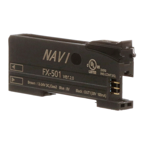
Panasonic FX-501 Series User manual

Panasonic

Panasonic FX-501 Series User manual

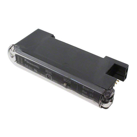
Panasonic GA-311 User manual

Panasonic

Panasonic GA-311 User manual

Panasonic CY-M9054 Operating User manual

Panasonic

Panasonic CY-M9054 Operating User manual

Panasonic SU-373 User manual

Panasonic

Panasonic SU-373 User manual

Panasonic RM-1100 User manual

Panasonic

Panasonic RM-1100 User manual

Panasonic FX-502 User manual

Panasonic

Panasonic FX-502 User manual

Panasonic PAMIS WA-BA240N User manual

Panasonic

Panasonic PAMIS WA-BA240N User manual

Panasonic WP9440 - RAMSA POWER AMPS User manual

Panasonic

Panasonic WP9440 - RAMSA POWER AMPS User manual

Panasonic FX-550L Series User manual

Panasonic

Panasonic FX-550L Series User manual

Panasonic SU-MED640P User manual

Panasonic

Panasonic SU-MED640P User manual

Panasonic CYM7002EUC - AUTO POWER AMPLIFIER User manual

Panasonic

Panasonic CYM7002EUC - AUTO POWER AMPLIFIER User manual

Panasonic FX-505 C2 Series User manual

Panasonic

Panasonic FX-505 C2 Series User manual

Panasonic CY-PA2003W User manual

Panasonic

Panasonic CY-PA2003W User manual

Panasonic CY-PAD1003N User manual

Panasonic

Panasonic CY-PAD1003N User manual

Panasonic MINAS-BL GU series User manual

Panasonic

Panasonic MINAS-BL GU series User manual

Panasonic Ramsa WZ-AD96M User manual

Panasonic

Panasonic Ramsa WZ-AD96M User manual

Panasonic CY-PA4003N User manual

Panasonic

Panasonic CY-PA4003N User manual

Panasonic FX-550L Series User manual

Panasonic

Panasonic FX-550L Series User manual

Panasonic WJ300C - SWITCHER/CONTROLLER User manual

Panasonic

Panasonic WJ300C - SWITCHER/CONTROLLER User manual

Panasonic RAMSA WP-1200 User manual

Panasonic

Panasonic RAMSA WP-1200 User manual

Popular Amplifier manuals by other brands

Russound DPA-4.8 instruction manual

Russound

Russound DPA-4.8 instruction manual

Crown Macro-Tech MA-1200 Schematic diagram

Crown

Crown Macro-Tech MA-1200 Schematic diagram

AR 2000TP2G8B Operating and service manual

AR

AR 2000TP2G8B Operating and service manual

Rega Ear user manual

Rega

Rega Ear user manual

IRT Electronics DDA-4010 user manual

IRT Electronics

IRT Electronics DDA-4010 user manual

Dynacord DSA 8405 owner's manual

Dynacord

Dynacord DSA 8405 owner's manual

Massive Audio DRAGO Series owner's manual

Massive Audio

Massive Audio DRAGO Series owner's manual

Baldwin Boxall Vigil 3 installation instructions

Baldwin Boxall

Baldwin Boxall Vigil 3 installation instructions

L.R. Baggs Duet II user guide

L.R. Baggs

L.R. Baggs Duet II user guide

ALLNIC AUDIO H-6500 owner's manual

ALLNIC AUDIO

ALLNIC AUDIO H-6500 owner's manual

FONESTAR FS-2020 instruction manual

FONESTAR

FONESTAR FS-2020 instruction manual

Jabra HT-Two Specifications

Jabra

Jabra HT-Two Specifications

Peavey Reno 400 user guide

Peavey

Peavey Reno 400 user guide

Conrad-Johnson MV45 owner's manual

Conrad-Johnson

Conrad-Johnson MV45 owner's manual

Creek Audio EVO operating instructions

Creek Audio

Creek Audio EVO operating instructions

Milmega Ametek AS Series Operation manual

Milmega

Milmega Ametek AS Series Operation manual

Pioneer SA-V220 operating instructions

Pioneer

Pioneer SA-V220 operating instructions

SAE TXQ Series user manual

SAE

SAE TXQ Series user manual

manuals.online logo
manuals.online logoBrands
  • About & Mission
  • Contact us
  • Privacy Policy
  • Terms and Conditions

Copyright 2025 Manuals.Online. All Rights Reserved.