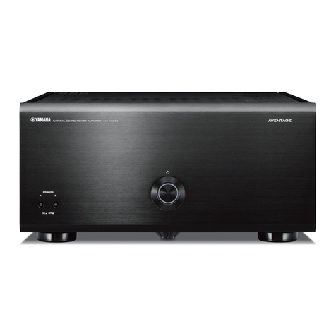
Yamaha MX-A5000 User manual

English
Français
Deutsch
Español
Русский
中文
한국어
Power Amplifier/Ampli de Puissance
Owner’s Manual
Mode d’emploi
Bedienungsanleitung
Manual de Instrucciones
Инструкция по эксплуатации
使用说明书
사용 설명서
MX-A5000_om_UCTKABGLVF.book Page 1 Thursday, April 4, 2013 5:28 PM

iEn
Precaution for use
Read the supplied booklet “Safety Brochure” before using the unit.
Install the unit in a well ventilated, cool, dry, clean place – away from direct sunlight,
heat sources, vibration, dust, moisture, and/or cold. Allow ventilation space of at
least 30 cm (11-3/4”) on the top, 20 cm (7-7/8”) on the left and right, and 20 cm
(7-7/8”) on the back of the unit.
30 cm (11-3/4”) or more
20 cm (7-7/8”) or more
Since the unit adopts bare metallic speaker terminals, make sure keeping enough
space on the back of the unit. If the speaker terminals come into contact with metal
parts of the AV rack, etc., the unit will be shortened and damaged.
Also, never touch the speaker terminals when the unit is powered on since it may
cause an electrical shock.
The unit does not have volume controls. Make sure you connect a device with
volume control (such as a pre-amplifier) to the unit. If you connect a device without
volume control (such as a CD player) directly to the unit, the volume may become
excessively loud and result in damage to the unit or speakers.
Be careful with short circuits.
DO NOT TOUCH!
(when the unit is powered on)
MX-A5000_om_UCTKABGLVF.book Page i Thursday, April 4, 2013 5:28 PM

En 1
CONTENTS
Precaution for use . . . . . . . . . . . . . . . . . . . . . . . . . . . . . . . . . . . . . . . . . . . . . . . .i
Accessories . . . . . . . . . . . . . . . . . . . . . . . . . . . . . . . . . . . . . . . . . . . . . . . . . . . . . . 1
Features . . . . . . . . . . . . . . . . . . . . . . . . . . . . . . . . . . . . . . . . . . . . . . . . . . . . . . . . 2
Part names and functions . . . . . . . . . . . . . . . . . . . . . . . . . . . . . . . . . . . . . . . . 3
Front panel . . . . . . . . . . . . . . . . . . . . . . . . . . . . . . . . . . . . . . . . . . . . . . . . . . . . . . . . . . . . . . . . . . . . . . . . . . . . . . . . . . . . . . . . 3
Rear panel . . . . . . . . . . . . . . . . . . . . . . . . . . . . . . . . . . . . . . . . . . . . . . . . . . . . . . . . . . . . . . . . . . . . . . . . . . . . . . . . . . . . . . . . . 4
Connections . . . . . . . . . . . . . . . . . . . . . . . . . . . . . . . . . . . . . . . . . . . . . . . . . . . . . 6
Connecting speakers . . . . . . . . . . . . . . . . . . . . . . . . . . . . . . . . . . . . . . . . . . . . . . . . . . . . . . . . . . . . . . . . . . . . . . . . . . . . . . . 7
Connecting the power cable . . . . . . . . . . . . . . . . . . . . . . . . . . . . . . . . . . . . . . . . . . . . . . . . . . . . . . . . . . . . . . . . . . . . . . . 8
Turning on/off the unit . . . . . . . . . . . . . . . . . . . . . . . . . . . . . . . . . . . . . . . . . . . . . . . . . . . . . . . . . . . . . . . . . . . . . . . . . . . . . 8
Other functions . . . . . . . . . . . . . . . . . . . . . . . . . . . . . . . . . . . . . . . . . . . . . . . . . . 8
Turning off the unit automatically (auto-standby function) . . . . . . . . . . . . . . . . . . . . . . . . . . . . . . . . . . . . . . . . . . 8
Dimming the power indicator . . . . . . . . . . . . . . . . . . . . . . . . . . . . . . . . . . . . . . . . . . . . . . . . . . . . . . . . . . . . . . . . . . . . . . 8
Turning on the unit in conjunction with operating other devices (trigger function) . . . . . . . . . . . . . . . . . . . 9
Advanced speaker configuration . . . . . . . . . . . . . . . . . . . . . . . . . . . . . . . . 10
Using a speaker that supports bi-amp connection . . . . . . . . . . . . . . . . . . . . . . . . . . . . . . . . . . . . . . . . . . . . . . . . . . 10
Using two pairs of front speakers (SPEAKERS A/B) . . . . . . . . . . . . . . . . . . . . . . . . . . . . . . . . . . . . . . . . . . . . . . . . . . 10
Using three speakers for one channel (multi-speaker) . . . . . . . . . . . . . . . . . . . . . . . . . . . . . . . . . . . . . . . . . . . . . . 10
Appendix . . . . . . . . . . . . . . . . . . . . . . . . . . . . . . . . . . . . . . . . . . . . . . . . . . . . . . 11
Input-output signal path diagram . . . . . . . . . . . . . . . . . . . . . . . . . . . . . . . . . . . . . . . . . . . . . . . . . . . . . . . . . . . . . . . . . 11
Troubleshooting . . . . . . . . . . . . . . . . . . . . . . . . . . . . . . . . . . . . . . . . . . . . . . . . . . . . . . . . . . . . . . . . . . . . . . . . . . . . . . . . . . 12
Specifications . . . . . . . . . . . . . . . . . . . . . . . . . . . . . . . . . . . . . . . . . . . . . . . . . . . . . . . . . . . . . . . . . . . . . . . . . . . . . . . . . . . . . 13
Accessories
Check that the following accessories are supplied with the product.
Power cable
*The supplied power cable varies depending on the region of purchase.
System control cable
Owner’s Manual
• Due to product improvements, specifications and appearance are subject to change without notice.
• indicates precautions for use of the unit and its feature limitations.
• indicates supplementary explanations for better use.
MX-A5000_om_UCTKABGLVF.book Page 1 Thursday, April 4, 2013 5:28 PM

2En Features
Features
High-quality power amplifier
■High output/high audio-quality
amplifier (150 W x 11 channels)
The unit provides an 11-channel power amplifier
featuring a three-stage Darlington current feedback
circuit, with a power supply that uses the same type of
toroidal transformer used in top-level hi-fi audio devices.
The gold-plated speaker connectors are also of the
highest quality, delivering high-grade sound.
■Balance and unbalanced
connections are supported
Balanced (XLR) and unbalanced (RCA) input jacks are
provided on all channels, and can be selected
independently for each channel.
Balanced connections minimize the extraneous noise
that can arise in the cable connection between the unit
and the pre-amplifier, ensuring high-fidelity transmission
of the audio signal.
Unbalanced connections utilize ground-sensing to
achieve fidelity that is close to balanced transmission.
■Chassis structure that maximizes
the potential of the unit's
performance
The chassis features a special structure that allows the
full potential of the high-quality power amplifier’s
potential to be revealed.
• Symmetrical power amplifier design
• Aluminum front panel and side panels
• Extremely stable feet utilizing the A.R.T.
(Anti-Resonance Technology)
Expandable to meet diverse needs
■Freedom for speaker placement
Since power amplifiers of the identical specification are
provided for all 11 channels, you use the unit not only
for constructing a home theater setup of up to
11 channels but also for multi-room systems or any
other speaker configuration to meet your needs.
■Support for bi-amp connections
and multi-speaker playback
The unit provides a channel selector function that lets
you utilize bi-amp connections or multi-speaker
connections without having to connect additional
cables from your pre-amplifier. For example, the CH.2
audio input could be output from both the CH.2 and
CH.3 speaker outputs to drive a bi-amp configuration
for high-quality sound, or the CH.1 (monaural) input
could be output from three speakers connected to CH.1
and CH.4 (L/R).
■Switch the unit's power from your
pre-amplifier (trigger function)
The unit can switch its own power status in
synchronization with power switching operations on
another device that supports the trigger function, such
as an AV pre-amplifier (TRIGGER IN). The input signal
from the TRIGGER IN jack can also be output without
change in a cascade connection to switch the power of
another device such as a Yamaha subwoofer
(THROUGH OUT). In addition, another device can be
switched in synchronization when the power of the unit
is switched (TRIGGER OUT), allowing you to set up a
variety of systems with synchronized power switching.
Pre-amplifier
MX-A5000_om_UCTKABGLVF.book Page 2 Thursday, April 4, 2013 5:28 PM

Part names and functions En 3
Front panel
1z(power) key
Turns on/off (standby) the unit (p.8).
2Power indicator
Lights up when the unit is turned on.
If the indicator blinks, the protection circuitry has been
activated. For details, see “Troubleshooting” (p.12).
• You can dim the power indicator (p.8).
3SPEAKERS A/B keys
Turns on /off the speakers connected to the CH.2 A/B
terminals (p.10).
• Both the speakers (A and B) are turned off by default. Press the
key to turn on the speakers you want to use.
• When using two pairs of the speakers connected to the CH.2
A/B terminals at the same time, be sure to use 8-ohm speakers
and set IMPEDANCE SELECTOR to the upper position (p.7).
Part names and functions
SPEAKERS
ON OFF
AB
21
3
MX-A5000_om_UCTKABGLVF.book Page 3 Thursday, April 4, 2013 5:28 PM

4En Part names and functions
Rear panel
1SPEAKERS terminals
For connecting to speakers (p.7).
2TRIGGER jacks
For connecting to devices that support the trigger function (p.9).
3AUTO POWER STANDBY switch
Enables/disables the auto-standby function (p.8).
4IMPEDANCE SELECTOR
Changes the unit’s speaker impedance setting depending
on the speakers connected (p.7).
5AC IN jack
For connecting the supplied power cable (p.8).
6CH. SELECTOR
(CH.3, CH.4 and CH.6 only)
Selects the audio source input to the CH.3, CH.4 or CH.6
amplifier when applying a bi-amp connection (p.10) or a
multi-speaker connection (p.10).
AC IN
RR
SPEAKERS
TRIGGER
INPUT
+12V
IN
THROUGH
OUT
BAL. UNBAL.
AUTO POWER
STANDBY
IMPEDANCE
SELECTOR
SELECTEUR
D’IMPEDANCE
OUT
OFF
ON
CH.6
CH.5
CH.5
CH.4
CH.3
CH.2
B
CH.2
A
CH.1
L
SPEAKERS
CH.6
CH.5
CH.4
CH.3
CH.2
B
CH.2
A
12V 0.1A
R
BAL. UNBAL.
CH.2
BAL. UNBAL.
CH.1
L
BAL. UNBAL.
CH.2
L
BAL. UNBAL.
CH.5
R
BAL. UNBAL.
CH.6
CH. SELECTOR
CH.5 CH.6
R
BAL. UNBAL.
CH.3
CH. SELECTOR
CH.2 CH.3
R
BAL. UNBAL.
CH.4
CH. SELECTOR
CH.1 CH.4
L
BAL. UNBAL.
CH.4
CH. SELECTOR
CH.1 CH.4
L
BAL. UNBAL.
CH.3
CH. SELECTOR
CH.2 CH.3
L
BAL. UNBAL.
CH.6
CH. SELECTOR
CH.5 CH.6
BAL. UNBAL.
CH. SELECTOR
3
4 5
6
7
8
9
11 2
Caution
• Remove the unit’s power cable from an AC wall outlet before
making any connections or operating the switches and/or
selectors.
MX-A5000_om_UCTKABGLVF.book Page 4 Thursday, April 4, 2013 5:28 PM

Part names and functions En 5
7INPUT (XLR) jack
For connecting to a pre-amplifier with XLR output jacks (p.6).
To use the XLR jack, set the corresponding BAL/UNBAL
switch to “BAL”.
When connecting an XLR balanced cable, match the pins
and insert the “male” connector of the cable until you hear a
click.
• When disconnecting the cable from the unit, hold down the PUSH
button on the unit and then pull the connector out.
8INPUT (RCA) jack
For connecting to a pre-amplifier with RCA output jacks
(p.6).
To use the RCA jack, set the corresponding BAL/UNBAL
switch to “UNBAL”.
• Remove the RCA short pins attached to the INPUT (RCA) jacks
before making connections. Be sure to keep them in a place
inaccessible to small children who may accidentally swallow
small parts.
• To protect against noise contamination, we recommend
attaching the RCA short pins when the INPUT (RCA) jacks are
not in use.
9BAL/UNBAL switch
Switches between XLR input and RCA input for each channel
(p.6).
About the XLR jacks
• The pin assignments for the XLR jacks of the unit are shown
below. Before connecting an XLR balanced cable, refer to the
instruction manual of your pre-amplifier and verify that its XLR
output jacks are compatible with the pin assignments.
BAL. UNBAL.
XLR balanced cable (male)
3. COLD
2. HOT 1. GND
BAL. UNBAL .
RCA cable
RCA short pin
MX-A5000_om_UCTKABGLVF.book Page 5 Thursday, April 4, 2013 5:28 PM

6En Connections
Connect a pre-amplifier and speakers to the unit.
To connect a pre-amplifier, use an XLR balanced cable (for balanced connection) or an RCA unbalanced cable (for unbalanced connection) for each channel depending on the
output jacks available on your pre-amplifier.
Connections
Caution
• Remove the unit’s power cable from an AC wall outlet before making any connections or operating the switches and/or selectors.
AC IN
RR
SPEAKERS
TRIGGER
INPUT
+12V
IN
THROUGH
OUT
BAL. UNBAL.
AUTO POWER
STANDBY
IMPEDANCE
SELECTOR
SELECTEUR
D’IMPEDANCE
OUT
OFF
ON
CH.6
CH.5
CH.5
CH.4
CH.3
CH.2
B
CH.2
A
CH.1
L
SPEAKERS
CH.6
CH.5
CH.4
CH.3
CH.2
B
CH.2
A
12V 0.1A
R
BAL. UNBAL.
CH.2
BAL. UNBAL.
CH.1
L
BAL. UNBAL.
CH.2
L
BAL. UNBAL.
CH.5
R
BAL. UNBAL.
CH.6
CH. SELECTOR
CH.5 CH.6
R
BAL. UNBAL.
CH.3
CH. SELECTOR
CH.2 CH.3
R
BAL. UNBAL.
CH.4
CH. SELECTOR
CH.1 CH.4
L
BAL. UNBAL.
CH.4
CH. SELECTOR
CH.1 CH.4
L
BAL. UNBAL.
CH.3
CH. SELECTOR
CH.2 CH.3
L
BAL. UNBAL.
CH.6
CH. SELECTOR
CH.5 CH.6
BAL. UNBAL .
XLR
XLR
The unit (rear)
SPEAKERS (R) terminals SPEAKERS (L) terminals
INPUT (XLR or RCA) jacks
* Set the BAL/UNBAL switch for each channel
to “BAL” (XLR) or “UNBAL” (RCA)
depending on the connection type.
Pre-amplifier
Preout (XLR or RCA)
jacks
Subwoofer connections
* For details, refer to the instruction manuals
for your pre-amplifier and subwoofers.
Speaker connections (p.7)
MX-A5000_om_UCTKABGLVF.book Page 6 Thursday, April 4, 2013 5:28 PM

Connections En 7
Connecting speakers
■Note on the speaker impedance
The unit supports the following speaker impedance.
• CH.2 A/B: 4 or more (8 or more when using CH.2 A and CH.2 B at the same time)
• Other channels: 6 or more
Set the IMPEDANCE SELECTOR to the upper/lower position depending on the
speakers connected to the unit.
■Connecting speaker cables
Speaker cables have two wires. One is for connecting the negative (-) terminal of the unit and
the speaker, and the other is for the positive (+) terminal. If the wires are colored to prevent
confusion, connect the black wire to the negative and the other wire to the positive terminal.
aRemove approximately 10 mm (0.40 in) of insulation from the ends of the speaker cable,
and twist the bare wires of the cable firmly together.
bLoosen the speaker terminal.
cInsert the bare wires of the cable into the gap on the side (upper left or bottom right) of the
terminal.
dTighten the terminal.
Using a banana plug
(U.S.A., Canada, China, Taiwan and Australia models only)
aTighten the speaker terminal.
bInsert a banana plug into the end of the terminal.
Using a Y-shaped lug connector
aLoosen the speaker terminal.
bInsert the Y-shaped lug connector into the groove between the knob and base part of the
terminal.
cTighten the terminal.
Upper position
Select this option when your speaker system meets one of the followings.
• When connecting speakers with impedance of less than 8 (4 or more) to the
CH.2 A or CH.2 B terminal
• When using two pairs of speakers connected to the CH.2 A/B terminals at the
same time (be sure to use 8-ohm speakers for both CH.2 A and CH.2 B)
• When connecting speakers with impedance of less than 8 (6 or more) to
speaker terminals other than CH.2 A or CH.2 B
Lower position
(default) Select this option when using speakers with impedance of 8 or more only.
aa
b
b
d
d
c
c
aa b
b
Banana plug
aa
b
b
c
c
Use a Y-shaped lug
with the following size.
6.5 mm
(0.26 in)
or more
MX-A5000_om_UCTKABGLVF.book Page 7 Thursday, April 4, 2013 5:28 PM

8En Other functions
Connecting the power cable
After all the connections and switch operations are complete, connect the supplied
power cable to the unit and then to an AC wall outlet.
Turning on/off the unit
Press z(power) to turn on/off the unit.
When the unit is turned on, the power indicator lights up.
• When an external device is connected to the TRIGGER IN jack, the unit is set to standby mode after
z(power) is pressed. If you turn on the external device, the unit automatically turns on by the trigger
function (p.9).
Turning off the unit automatically
(auto-standby function)
The unit will automatically go into standby mode 8 hours after the unit is turned on.
To disable the auto-standby function, set the AUTO POWER STANDBY switch to “OFF”.
• The auto-standby function works even if playback is ongoing.
• When the system control cable is connected to the TRIGGER IN jack, the auto-standby function does not
work even if it is enabled.
Dimming the power indicator
You can dim the power indicator on the front panel of the unit.
• When an external device is connected to the TRIGGER IN jack, turn on it before performing the following
procedure.
aIf the unit is turned on, press z(power) to turn off it.
bPress z(power) three times within 3 seconds.
The power indicator dims.
• To cancel the dimmer, perform the procedure again.
• If the power cable is unplugged, the dimmer will be canceled.
AC IN
CH.4
CH.3
CH.2
B
CH.2
A
L
BAL. UNBAL.
CTOR
H.4
L
BAL. UNBAL.
CH.3
CH. SELECTOR
CH.2 CH.3
L
BAL. UNBAL.
CH.6
CH. SELECTOR
CH.5 CH.6
To an AC wall outlet
The unit (rear)
z(power)
The unit (front)
Other functions
MX-A5000_om_UCTKABGLVF.book Page 8 Thursday, April 4, 2013 5:28 PM

Other functions En 9
Turning on the unit in conjunction with operating other devices (trigger function)
The trigger function can control power of the unit in conjunction with operating other
devices or control power of other devices in conjunction with turning on/off the unit. If
you have a power amplifier or a Yamaha subwoofer that supports the trigger function,
you can use the trigger function by connecting your devices to the TRIGGER jacks with
the supplied system control cable.
Depending on the intended use, connect your device to one of the following TRIGGER
jacks.
IN jack:
For connecting a device that supports the trigger output function (such as a
pre-amplifier).
If you turn on/off your device, the unit will automatically turns on/off (standby).
• This function is available only when z(power) of the unit is on (pressed down).
THROUGH OUT jack:
This jack outputs signals input from the IN jack.
If you connect a device that supports the trigger input function (such as another power
amplifier), your device will automatically turn on/off in conjunction with turning on/off the
device connected to the IN jack.
OUT jack:
For connecting a device that supports the trigger input function (such as a subwoofer).
If you turn on/off (standby) the unit, your device will automatically turns on/off.
• To connect multiple devices to the TRIGGER jacks, you need to prepare commercially-available monaural
mini-plug cables.
R
TRIGGER
+12V
IN
THROUGH
OUT
BAL. UNBAL.
AUTO POWER
STANDBY
IMPEDANCE
SELECTOR
SELECTEUR
D’IMPEDANCE
OUT
OFF
ON
CH.5
12V 0.1A
R
CH.2
R
BAL. UNBAL.
CH.6
CH. SELECTOR
CH.5 CH.6
R
CH.3
CH. SELECTOR
CH.2 CH.3
TRIGGER
+12V
IN
THROUGH
OUT
OUT
12V 0.1A
The unit
(rear)
Another
power
amplifier
Trigger Out
(+12 V)
TRIGGER
(IN/THROUGH OUT/OUT) jacks
System connection
input
Pre-amplifier
(such as
CX-A5000)
Subwoofer
Trigger In
(+12 V)
MX-A5000_om_UCTKABGLVF.book Page 9 Thursday, April 4, 2013 5:28 PM

10 En Advanced speaker configuration
Using a speaker that supports bi-amp connection
If you want to use a speaker that supports bi-amp connection to have more high-quality
sounds, change the CH. SELECTOR setting and connect the speaker to the
corresponding pair of the SPEAKERS terminals.
(Example)
Using a speaker that supports bi-amp connection for CH.2 (R)
By setting the CH. SELECTOR for CH.3 (R) to “CH.2”, CH.2 (R) input signals are output
from both the CH.2 (R) and CH.3 (R) speaker terminals. In this case, CH.3 (R) input is
not used.
Using two pairs of front speakers (SPEAKERS A/B)
If you connect two pairs of front speakers to the CH.2 A/B terminals, you can switch the
front speakers to be used by pressing SPEAKERS A/B on the front panel of the unit.
• When using two pairs of the speakers connected to the CH.2 A/B terminals at the same time, be sure to
use 8-ohm speakers and set IMPEDANCE SELECTOR to the upper position (p.7).
Using three speakers for one channel (multi-speaker)
If you want to use three speakers for reproducing CH.1 audio signals (such as center
channel signals), change the CH. SELECTOR setting and connect the speakers to the
CH.1 and CH.4 (L/R) terminals.
Advanced speaker configuration
Caution
• Remove the unit’s power cable from an AC wall outlet before making any connections or operating the
switches.
Caution
• Before making bi-amp connections, remove any brackets or cables that connect a woofer with a
tweeter. Refer to the instruction manual of the speakers for details. If you are not making bi-amp
connections, make sure that the brackets or cables are connected before connecting the speaker
cables.
RR
SPEAKERS
TRIGGER
+12V
IN
THROUGH
OUT
BAL. UNBAL.
AUTO POWER
STANDBY
IMPEDANCE
SELECTOR
SELECTEUR
D’IMPEDANCE
OUT
OFF
ON
CH.6
CH.5
CH.5
CH.4
CH.3
CH.2
B
CH.2
A
CH.1
12V 0.1A
R
BAL. UNBAL.
CH.2
R
BAL. UNBAL.
CH.6
CH. SELECTOR
CH.5 CH.6
R
BAL. UNBAL.
CH.3
CH. SELECTOR
CH.2 CH.3
CH
CH. S
E
CH.1
R
CH.3
CH. SELECTOR
CH.2 CH.3
The unit (rear) Input from pre-amplifier
CH.2 A (R) and
CH.3 (R) terminals
Set CH. SELECTOR
for CH.3 (R) to “CH.2”
CH.2
B
CH.2
A
CH.2
B
CH.2
A
The unit (rear)
CH.2 A/B (L)
terminals
CH.2 A/B (R)
terminals
CH.4
CH.2
CH.4
BAL. UNBAL.
CH.1
R
CH.4
CH. SELECTOR
CH.1 CH.4
L
CH.4
CH. SELECTOR
CH.1 CH.4
The unit (rear)
Set CH. SELECTOR
for CH.4 (R) and
CH.4 (L) to “CH.1”
Input from pre-amplifier
CH.4 (R)
terminal CH.4 (L)
terminal
CH.1
terminal
MX-A5000_om_UCTKABGLVF.book Page 10 Thursday, April 4, 2013 5:28 PM

Appendix En 11
Input-output signal path diagram
Appendix
BAL
UNBAL
SPEAKER A/B
B
A
CH.3
CH.2
CH.4
CH.1
CH.6
CH.5
CH.6
CH.5
CH.4
CH.3
CH.2
CH.1
UNBAL
BAL
UNBAL
BAL
UNBAL
BAL
UNBAL
BAL
UNBAL
BAL
UNBAL
BAL
CH.6
CH.5
CH.4
CH.1
CH.3
CH.2
CH.6
CH.5
CH.4
CH.3
SPEAKER A/B
B
A
CH.1
BAL
UNBAL
BAL
UNBAL
BAL
UNBAL
BAL
UNBAL
CH.2
B
CH.2
A
CH.2
B
CH.2
A
CH.6
CH.5
CH.4
CH.3
RL
R
R
R
R
RL
L
L
L
L
INPUT (RCA/XLR) jacks
BAL/UNBAL switch CH SELECTORCH SELECTOR BAL/UNBAL switch
SPEAKERS (L) terminals
SPEAKERS (R) terminals
MX-A5000_om_UCTKABGLVF.book Page 11 Thursday, April 4, 2013 5:28 PM

12 En Appendix
Troubleshooting
Refer to the table below when the unit does not function properly.
If the problem you are experiencing is not listed below or if the instructions below do not help, turn off the unit, disconnect the power cable, and contact the nearest authorized
Yamaha dealer or service center.
First, check the followings:
aThe power cables of the unit and other devices (such as a pre-amplifier) are connected to AC wall outlets securely.
bThe unit and other devices (such as a pre-amplifier) are turned on.
cThe connectors of each cable are securely inserted in to jacks on each device.
Problem Cause Remedy
The power does not turn on.
The protection circuitry has been activated three times
consecutively. When the unit is in this condition, the power
indicator on the unit blinks.
As a safety precaution, capability to turn on the power is disabled. Contact your
nearest Yamaha dealer or service center to request repair.
The internal microcomputer has frozen, due to an external electric
shock (such as lightning or excessive static electricity) or to a drop
in the power supply voltage.
Disconnect the power cable from the AC wall outlet and plug it again.
An external device is connected to the TRIGGER (IN) jack. Press down z(power) on the unit and then turn on the external device.
The power turns off (standby mode) immediately.
The unit was turned on while a speaker cable was shorted. Twist the bare wires of each speaker cable firmly and reconnect to the unit and
speakers (p.7).
The unit was shorted because the speaker terminals come into
contact with metal parts of the AV rack, etc. Keep enough space on the back of the unit (p.i).
The unit enters standby mode automatically.
The auto-standby function worked. To disable the auto-standby function, set the AUTO POWER STANDBY switch to
“OFF” (p.8).
The protection circuitry has been activated because the volume of
the external device connected to the unit is too high. Turn down the volume of the external device.
The protection circuitry has been activated because the
temperature inside of the unit is too high.
Install the unit in a well ventilated, place and allow enough ventilation space
around the unit (p.i).
No sound. The BAL/UNBAL switch setting is not correct. Change the BAL/UNBAL switch setting so that it matches the connections (p.6).
No sound is coming from a specific speaker.
The speakers connected to the CH.2 A/B terminals are turned off. Press SPEAKERS A/B to turn on the speakers (p.10).
The XLR balanced cable (or RCA unbalanced cable) connecting
the unit and pre-amplifier is defective, or the speaker cable
connecting the unit and speaker is defective.
If there is no problem with the connection, replace with another cable.
Another channel sound is coming from a specific
speaker. The CH SELECTOR setting is not correct. Change the CH SELECTOR setting so that it matches your speaker system (p.10).
MX-A5000_om_UCTKABGLVF.book Page 12 Thursday, April 4, 2013 5:28 PM

Appendix En 13
Specifications
Input jacks
•Audio
Analog RCA (Unbalance) x 11
Analog XLR (Balance) x 11 (1:GND, 2:HOT, 3:COLD)
Output jacks
•Audio
Speaker Out x 11 ch
(13 Terminals: CH.1, CH.2-A [L/R], CH.2-B [L/R], CH.3 [L/R] to
CH.6 [L/R])
Other jacks
• TRIGGER OUT x 1 (+12 V/0.1 A max.)
• TRIGGER IN x 1 (+12 V In)
• TRIGGER THROUGH OUT x 1
Audio Section
• Rated Output Power (2-channel driven)
(20 Hz to 20 kHz, 0.06% THD, 6 )
CH.1................................................................................ 170 W
CH.2 (L/R)....................................................................... 170 W
CH.3 (L/R)....................................................................... 170 W
CH.4 (L/R)....................................................................... 170 W
CH.5 (L/R)....................................................................... 170 W
CH.6 (L/R)....................................................................... 170 W
(20 Hz to 20 kHz, 0.06% THD, 8 )
CH.1................................................................................ 150 W
CH.2 (L/R)....................................................................... 150 W
CH.3 (L/R)....................................................................... 150 W
CH.4 (L/R)....................................................................... 150 W
CH.5 (L/R)....................................................................... 150 W
CH.6 (L/R)....................................................................... 150 W
(1 kHz, 0.9% THD, 8 )
CH.1................................................................................ 170 W
CH.2 (L/R)....................................................................... 170 W
CH.3 (L/R)....................................................................... 170 W
CH.4 (L/R)....................................................................... 170 W
CH.5 (L/R)....................................................................... 170 W
CH.6 (L/R)....................................................................... 170 W
• Rated Output Power (1-channel driven)
(1 kHz, 0.9% THD, 6 )
CH.1 ...........................................................................230 W/ch
CH.2 (L/R) ..................................................................230 W/ch
CH.3 (L/R) ..................................................................230 W/ch
CH.4 (L/R) ..................................................................230 W/ch
CH.5 (L/R) ..................................................................230 W/ch
CH.6 (L/R) ..................................................................230 W/ch
(1 kHz, 0.9% THD, 8 )
CH.1 ...........................................................................190 W/ch
CH.2 (L/R) ..................................................................190 W/ch
CH.3 (L/R) ..................................................................190 W/ch
CH.4 (L/R) ..................................................................190 W/ch
CH.5 (L/R) ..................................................................190 W/ch
CH.6 (L/R) ..................................................................190 W/ch
(1 kHz, 0.9% THD, 4 )
CH.2 (L/R) [U.K. and Europe models]........................290 W/ch
• Maximum Effective Output Power (1-channel driven, JEITA)
[China, Taiwan, Korea and Asia models]
(1 kHz, 10% THD, 6 )
CH.1 ...........................................................................280 W/ch
CH.2 (L/R) ..................................................................280 W/ch
CH.3 (L/R) ..................................................................280 W/ch
CH.4 (L/R) ..................................................................280 W/ch
CH.5 (L/R) ..................................................................280 W/ch
CH.6 (L/R) ..................................................................280 W/ch
(1 kHz, 10% THD, 8 )
CH.1 ...........................................................................230 W/ch
CH.2 (L/R) ..................................................................230 W/ch
CH.3 (L/R) ..................................................................230 W/ch
CH.4 (L/R) ..................................................................230 W/ch
CH.5 (L/R) ..................................................................230 W/ch
CH.6 (L/R) ..................................................................230 W/ch
• Dynamic Power (IHF)
1-channel driven (8/6/4/2 ) ......................190/250/350/500 W
• Damping Factor
All Channels, 1 kHz, 8 ....................................... 180 or more
• Input Sensitivity / Input Impedance
Unbalance (1 kHz, 100 W/8 ).............................. 1.0 V/47 k
Balance (1 kHz, 100 W/8 ) .................................. 2.0 V/47 k
• Maximum Input Signal
Unbalance (1 kHz, 0.5% THD, 8 ).....................1.3 V or more
Balance (1 kHz, 0.5% THD, 8 ) .........................2.6 V or more
• Frequency Response (10 Hz to 100 kHz)...................+0/-3 dB
• Total Harmonic Distortion (70 W/8 ) ............... 0.015% or less
• Signal to Noise Ratio (IHF-A Network)
(Input Shorted 1 k, Reference Level 150 W/8 )
......................................................................... 116 dB or more
• Residual Noise (IHF-A Network)
Speaker Out (Input Shorted)................................ 60 µV or less
• Channel Separation (Input 5.1 kShorted , 1 kHz/10 kHz)
...................................................................... 90/75 dB or more
• Gain...............................................................................29.1 dB
General
• Power Supply
[U.S.A. and Canada models]..........................AC 120 V, 60 Hz
[Taiwan model]................................ AC 110 to 120 V, 50/60 Hz
[China model] .................................................AC 220 V, 50 Hz
[Korea model] ................................................. AC 220 V, 60 Hz
[Australia model].............................................AC 240 V, 50 Hz
[U.K. and Europe models] .............................. AC 230 V, 50 Hz
[Asia model].................................... AC 220 to 240 V, 50/60 Hz
• Power Consumption
[U.S.A. and Canada models]..............................650 W/850 VA
[Korea model] .................................................................550 W
[Other models]................................................................650 W
• Standby Power Consumption ........................... 0.1 W (Typical)
• Maximum Power Consumption (All Channel driven, 10% THD)
[Taiwan and Asia models].............................................1500 W
• Power Consumption (No Signals) ...................... 75 W (Typical)
• Dimensions (W x H x D)
...................435 x 210 x 463.5 mm (17-1/8” x 8-1/4” x 18-1/8”)
* Including legs and protrusions
• Weight ...........................................................25.4 kg (56.0 lbs)
* Specifications are subject to change without notice.
MX-A5000_om_UCTKABGLVF.fm Page 13 Wednesday, May 1, 2013 4:08 PM

© 2013 Yamaha Corporation Printed in Malaysia ZG28970
MX-A5000_om_UCTKABGLVF.book Page 1 Thursday, April 4, 2013 5:28 PM

© 2013 Yamaha Corporation Printed in Malaysia ZH84160
By a combination of “AV Pre-Amplifier CX-A5000” and “Power Amplifier MX-A5000”, you can build a home theater system in a variety of ways. This guide
explains three representative connection manners for example. Please place the speakers in your room by using the following diagram as a reference.
• This guide explains connection examples only. For information on each terminal or required switch settings, refer to the instruction manual for each device.
• Before making connections, remove the power cable of each device.
En associant un « Préampli Audio-Vidéo CX-A5000 » et un « Ampli de Puissance MX-A5000 », vous pouvez créer un système Home Cinéma de différentes
manières. Ce guide décrit trois modes de raccordement représentatifs à titre d’exemple. Veuillez placer les enceintes dans la pièce de votre choix en vous
reportant au diagramme suivant.
• Ce guide présente uniquement des exemples de raccordement. Pour des informations relatives aux bornes ou pour connaître les réglages de permutation requis, reportez-vous au mode
d’emploi de chaque appareil.
• Avant d’effectuer les raccordements, débranchez le câble d’alimentation de chaque appareil.
Existen varias formas de crear un sistema de cine en casa combinando un “Pre-Amplificador AV CX-A5000” y un “Etapa de potencia MX-A5000”. En esta
guía se explican tres formas de conexión representativas a modo de ejemplo. Coloque los altavoces en la sala con ayuda del diagrama siguiente como
referencia.
• En esta guía solo se explican los ejemplos de conexión. Para obtener información sobre cada terminal o sobre los ajustes de conmutador necesarios, consulte el manual de instrucciones de
cada dispositivo.
• Antes de realizar las conexiones, quite el cable de alimentación de ambos dispositivos.
Ideal speaker layout / Disposition idéale des enceintes / Disposición óptima de los altavoces
Connection Example / Exemple de raccordement / Ejemplo de conexión
English
Français
Español
English
Français
Español
E
12
3
4
6
T Y
5
R
7
12 12
10°-30°10°-30°
1Front (L) / Avant (G) / Delantero (I)
2Front (R) / Avant (D) / Delantero (D)
3Center / Centre / Central
4Surround (L) / Surround (G) / Surround (I)
5Surround (R) / Surround (D) / Surround (D)
6Surround back (L) / Surround arrière (G) / Surround trasero (I)
7Surround back (R) / Surround arrière (D) / Surround trasero (D)
EFront presence (L) / Présence avant (G) / Presencia delantero (I)
RFront presence (R) / Présence avant (D) / Presencia delantero (D)
TRear presence (L) / Présence arrière (G) / Presencia trasero (I)
YRear presence (R) / Présence arrière (D) / Presencia trasero (D)
Subwoofer (1) / Subwoofer (1) / Subgraves (1)
Subwoofer (2) / Subwoofer (2) / Subgraves (2)
Zone2 Zone3
Main zone / Zone principale / Zona principal
a
Home theater system with maximum channels (11.2-ch)
Système Home Cinéma avec voies maximum (11.2 voies)
Sistema de cine en casa con máximo de canales (11.2 canales)
This system enables you to enjoy the highest peak of CINEMA DSP -
an 11.2-channel 3-dimensional sound field.
Ce système vous permet de profiter des meilleures performances de
CINEMA DSP (champ sonore 3D à 11.2 voies).
Este sistema le permite disfrutar del volumen máximo de CINEMA DSP:
un campo de sonido tridimensional de 11.2 canales.
123
4567
ERTY
(CX-A5000)
(MX-A5000)
English
Français
Español
• Set the BAL/UNBAL switch and CH. SELECTOR for each channel (on the rear of MX-A5000) as illustrated above.
• Réglez le commutateur BAL/UNBAL et CH. SELECTOR pour chaque voie (à l’arrière du MX-A5000) comme illustré ci-dessus.
• Establezca el conmutador BAL/UNBAL y CH. SELECTOR para cada canal (en la parte trasera del MX-A5000) como se indica en la ilustración anterior.
BAL.BAL.
BAL.BAL.
BAL.BAL.BAL.BAL.
BAL. BAL. BAL.
AC IN
RR
SPEAKERS
TRIGGER
INPUT
+12V
IN
THROUGH
OUT
UNBAL.
AUTO POWER
STANDBY
IMPEDANCE
SELECTOR
SELECTEUR
D’IMPEDANCE
OUT
OFF
ON
CH.6
CH.5
CH.5
CH.4
CH.3
CH.2
B
CH.2
A
CH.1
L
SPEAKERS
CH.6
CH.5
CH.4
CH.3
CH.2
B
CH.2
A
12V 0.1A
R
UNBAL.
CH.2
UNBAL.
CH.1
L
UNBAL.
CH.2
L
UNBAL.
CH.5
R
UNBAL.
CH.6
CH. SELECTOR
CH.5
R
UNBAL.
CH.3
CH. SELECTOR
CH.2
R
UNBAL.
CH.4
CH. SELECTOR
CH.1
L
UNBAL.
CH.4
CH. SELECTOR
CH.1
L
UNBAL.
CH.3
CH. SELECTOR
CH.2
L
UNBAL.
CH.6
CH. SELECTOR
CH.5CH.6 CH.3 CH.4 CH.4 CH.3 CH.6
TRIGGER
+12V
IN
Y
5
7
R
2
3
T
4
6
E
1
XLR
XLR
XLR
XLR
XLR
XLR
XLR XLR
XLR
XLR
XLR
XLR
XLR
XLR
XLR
XLR
XLR
XLR
XLR
XLR
XLR
XLR
(CX-A5000)
(MX-A5000)
UCABGLV

b
5-ch bi-amp system
Système bi-amplificateur à 5 voies
sistema de biamplificación de 5 canales
This system enables you to enjoy more high-quality sounds by making bi-amp
connections for all the 5-ch speakers (fig. A). For the center channel, you can
also use three center speakers instead of bi-amp connections (fig. B).
Ce système vous permet de profiter d’un son de meilleure qualité grâce à des
connexions bi-amplificatrices pour toutes les enceintes à 5 voies (figure A).
Pour la voie centrale, vous pouvez également utiliser trois enceintes centrales
au lieu de connexions bi-amplificatrices (figure B).
Con este sistema podrá disfrutar de más sonidos de alta calidad mediante
la realización de conexiones de biamplificación para todos los altavoces de
5 canales (fig. A). Para el canal central, puede también utilizar tres altavoces
centrales en vez de conexiones de biamplificación (fig. B).
1245
(bi-amp)
(bi-amplificateur)
(biamplificación)
3
(bi-amp / 3 speakers)
(bi-amplificateur / 3 enceintes)
(biamplificación / 3 altavoces)
(CX-A5000)
(MX-A5000)
(A)
(B)
English
Français
Español
• Set the BAL/UNBAL switch and CH. SELECTOR for each channel (on the rear of MX-A5000) as illustrated above.
• Réglez le commutateur BAL/UNBAL et CH. SELECTOR pour chaque voie (à l’arrière du MX-A5000) comme illustré ci-dessus.
• Establezca el conmutador BAL/UNBAL y CH. SELECTOR para cada canal (en la parte trasera del MX-A5000) como se indica en la ilustración anterior.
• To make a bi-amp connection for the center speaker (3), use any two of CH.1, CH.4 (L), and CH.4 (R) speaker terminals.
• Pour effectuer une connexion bi-amplificatrice pour l’enceinte centrale (3), utilisez deux bornes d’enceinte CH.1, CH.4 (L) ou CH.4 (R) de votre choix.
• Para realizar una conexión de biamplificación para el altavoz central (3), utilice cualquier combinación de dos de los terminales de altavoz CH.1, CH.4 (L) y CH.4 (R).
BAL.BAL.
BAL.BAL.
BAL.BAL.BAL.BAL.
BAL. BAL. BAL.
AC IN
RR
SPEAKERS
TRIGGER
INPUT
+12V
IN
THROUGH
OUT
UNBAL.
AUTO POWER
STANDBY
IMPEDANCE
SELECTOR
SELECTEUR
D’IMPEDANCE
OUT
OFF
ON
CH.6
CH.5
CH.5
CH.4
CH.3
CH.2
B
CH.2
A
CH.1
L
SPEAKERS
CH.6
CH.5
CH.4
CH.3
CH.2
B
CH.2
A
12V 0.1A
R
UNBAL.
CH.2
UNBAL.
CH.1
L
UNBAL.
CH.2
L
UNBAL.
CH.5
R
UNBAL.
CH.6
CH. SELECTOR
CH.5
R
UNBAL.
CH.3
CH. SELECTOR
CH.2
R
UNBAL.
CH.4
CH. SELECTOR
CH.1
L
UNBAL.
CH.4
CH. SELECTOR
CH.1
L
UNBAL.
CH.3
CH. SELECTOR
CH.2
L
UNBAL.
CH.6
CH. SELECTOR
CH.5CH.6 CH.3 CH.4 CH.4 CH.3 CH.6
TRIGGER
+12V
IN
5
3
2
3
4
3
1
XLR
XLR
XLR
XLR
XLR
XLR
XLR
XLR
XLR
XLR
(CX-A5000)
(MX-A5000)
c
5-ch main zone plus two 2-ch zones
Zone principale à 5 voies plus deux zones à 2 voies
zona principal de 5 canales más dos zonas de 2 canales
This system enables you to enjoy 5-ch surround sounds in the main zone
and stereo sounds in the other zones (Zone2 and Zone3). As necessary,
you can use two pairs of front speakers for Zone2 or Zone3.
Ce système vous permet de profiter d’un son surround à 5 voies dans la
zone principale et d’un son stéréo dans les autres zones (Zone2 et Zone3).
Vous pouvez, si nécessaire, utiliser deux paires d’enceintes avant pour la
Zone2 ou la Zone3.
Con este sistema puede disfrutar de sonidos surround de 5 canales en la
zona principal y sonidos estéreo en las otras zonas (Zone2 y Zone3). Si es
necesario, puede utilizar dos pares de altavoces delanteros para Zone2 o
Zone3.
12345
12
(2 pairs)
(2 paires)
(2 pares)
12
Zone2 Zone3
(CX-A5000)
(MX-A5000)
English
Français
Español
• Set the BAL/UNBAL switch and CH. SELECTOR for each channel (on the rear of MX-A5000) as illustrated above.
• Réglez le commutateur BAL/UNBAL et CH. SELECTOR pour chaque voie (à l’arrière du MX-A5000) comme illustré ci-dessus.
• Establezca el conmutador BAL/UNBAL y CH. SELECTOR para cada canal (en la parte trasera del MX-A5000) como se indica en la ilustración anterior.
BAL.BAL.
BAL.BAL.
BAL.BAL.BAL.BAL.
BAL. BAL. BAL.
AC IN
RR
SPEAKERS
TRIGGER
INPUT
+12V
IN
THROUGH
OUT
UNBAL.
AUTO POWER
STANDBY
IMPEDANCE
SELECTOR
SELECTEUR
D’IMPEDANCE
OUT
OFF
ON
CH.6
CH.5
CH.5
CH.4
CH.3
CH.2
B
CH.2
A
CH.1
L
SPEAKERS
CH.6
CH.5
CH.4
CH.3
CH.2
B
CH.2
A
12V 0.1A
R
UNBAL.
CH.2
UNBAL.
CH.1
L
UNBAL.
CH.2
L
UNBAL.
CH.5
R
UNBAL.
CH.6
CH. SELECTOR
CH.5
R
UNBAL.
CH.3
CH. SELECTOR
CH.2
R
UNBAL.
CH.4
CH. SELECTOR
CH.1
L
UNBAL.
CH.4
CH. SELECTOR
CH.1
L
UNBAL.
CH.3
CH. SELECTOR
CH.2
L
UNBAL.
CH.6
CH. SELECTOR
CH.5CH.6 CH.3 CH.4 CH.4 CH.3 CH.6
TRIGGER
+12V
IN
2
2
5
2
2
3
1
1
4
1
1
Zone2
Zone3
Zone3
Zone2
L
L
R
R
L
L
R
R
XLR
XLR
XLR
XLR
XLR
XLR
XLR
XLR
XLR
XLR
(CX-A5000)
(MX-A5000)

GYAMAHA
Power Amplifier
Ampli de Puissance
Safety Brochure
Brochure
sur
Ia Securite
Sicherheitsbroschure
Sakerhetsanvisningar
Volantino sulla sicurezza
Folleto
de
Seguridad
Veiligheidsbrochure
Sikkerhedsbrochure
Sikkerhetsbrosjyre
Turvallisuusohjeet
6pow10pa no
6eaonacHOCTM
~~¥-M
~~
AI~A-t
(!)
(Power key) Turns on the pow
er
of
this unit or sets it to the standby mode.
c9
(Touche d'alimentatlon) Mett
ez
l'appareil sous tension ou regl
ez
-le en mode de mise en veille.
(!)
(Hauptschalter)
Sc
halt
et
dieses Gerat ein
od
er versetzt es in den Bereitschaftsmodus.
c9
(Stromknapp) Slar pa stri:immen till denna enhet e
ll
er sta
ll
er den i beredskapslaget.
c9
(Tasto di alimentazione) Accende
l'
alimentazione
de
ll
'unita o
l'im
posta in modalita standby.
(!)
(Tecla de encendido) Enciende esta u
ni
dad o Ia pone en modo de espera.
(!)
(Stroomtoets)
Zet
het apparaat
aa
n
of
zet het in de
sta
nd-bystand.
(!)
(Stromknap) T
re
nder for str
!<l
mm
en til denne enhed eller stiller den
pa
standby.
(!)
(Str111mbryter)
Slar p
ll
str
!<lm
men til enheten, eller setter den i standby-modu
s.
(!)
(VIrtapainike) Kytkee tiihan laitteeseen virran tai asettaa laitteen valmiustilaan.
(!)
(KHonKa
nMT8HMA)
BKmoqe
Hne miTaH
IDI
arrrrapaTa
HJIH
ycTaHOBKa
ero
Bp
eX<HM
oX<n~a
H
Hll
.
l
c!><~~~•>
rrH*m~~
·
·~~~-~~m
•~-
I
1
<!>
c~!l
:m
i"':-
7]719
1
:
:;:H:J.%
7"17
-JLJ-
1:]1
71
s:..'=.oJ
l
'5-t4'~.A
J
.2...
1

•mm
IMPORTANT
SAFETY
INSTRUCTIONS
&
CAUTION
RISK
OF
ELECTRIC
SHOCK
DO
NOT
OPEN
&
CAUTION: TO REDUCE THE RISK OF
ELECTRIC SHOCK, DO NOT REMOVE
COVER (OR BACK). NO USER-SERVICEABLE
PARTS INSIDE. REFER SERVICING
TO
QUALIFIED SERVICE PERSONNEL.
• Explanation of Graphical Symbols
&
&
The
lightning flash with arrowhead symbol, within an equilateral triangle, is
intended to alert you to the presence
of
uninsulated "dangerous voltage" within the
product's enclosure that may be
of
sufficient magnitude to constitute a risk
of'
electric shock to persons.
The exclamation point within an equilateral triangle is intended to alert you to the
presence
of
important operating and maintenance (servicing) instructions in the
literature accompanying the appliance.
2
3
Read these instructions.
Keep these instructions.
Heed all warnings.
4 Follow all instructions.
5
Do
not use this apparatus near water.
6 Clean only with dry cloth.
7
Do
not block any ventilation openings. Install in accordance with the manufacturer's
instructions.
8
Do
not install near any heat sources such as radiators, heat registers, stoves,
or
other apparatus
(including amplifiers) that produce heat.
9
Do
not defeat the safety purpose
of
the polarized
or
grounding-type plug. A polarized plug has
two blades with
one
wider than the other. A grounding type plug has two blades and a third
grounding prong. The wide blade
or
the third prong are provided for your safety.
If
the
provided plug does not fit into your outlet, consult an electrician for replacement
of
the
obsolete outlet.
1 En
10
11
12
13
14
Protect the
power
cord from being walked on
or
pinched particularly at plugs, convenience
receptacles, and the point where they exit from the apparatus.
Only use attachments/accessories specified
by
the manufacturer.
Use only with the cart, stand, tripod, bracket,
or
table specified by the •
manufacturer,
or
sold with the apparatus.
When
a cart is used, use caution when
moving the cart/apparatus combination to avoid injury from tip-over. •
...
Unplug this apparatus during lightning storms
or
when unused for long periods
~~.
.
Refer all servicing to qualified service personnel. Servicing is required when the apparatus has
been damaged in any way, such as power-supply cord
or
plug is damaged, liquid has been
spilled
or
objects have fallen into the apparatus, the apparatus has been exposed to rain
or
moisture, does not operate normally, or has been dropped.
We Want You Listening For A Lifetime
g
LISTENING
Fai:ALiletime
Yamaha and the Electronic Industries Association's ConsumerElectronics Group want
you to get the most out
of
your equipment by playing it at a safe level. One that lets the
sound come through loud and clear without annoying blaring
or
distortion -and, most
importantly, without affecting your sensitive hearing. Since hearing damage from loud
sounds is often undetectable until it is too late, Yamaha and the Electronic Industries
Association's Consumer Electronics Group recommend you to avoid prolonged exposure from
excessive volume levels.
Other manuals for MX-A5000
1
Table of contents
Other Yamaha Amplifier manuals

Yamaha
Yamaha DSP-A1092 User manual

Yamaha
Yamaha M-45 User manual

Yamaha
Yamaha H5000 User manual

Yamaha
Yamaha AX-892 User manual

Yamaha
Yamaha DSP-A970 User manual

Yamaha
Yamaha PC2002 User manual

Yamaha
Yamaha MX-D1 - Amplifier User manual

Yamaha
Yamaha XMV4280 User manual

Yamaha
Yamaha A-S2000 - Amplifier User manual

Yamaha
Yamaha PC2002 User manual

Yamaha
Yamaha A-U671 User manual

Yamaha
Yamaha 001PO-03C0 User manual

Yamaha
Yamaha DSP-A500 User manual

Yamaha
Yamaha XP5000 User manual

Yamaha
Yamaha WXA-50 User manual

Yamaha
Yamaha THR30II Wireless User manual

Yamaha
Yamaha AVX-20 User manual

Yamaha
Yamaha M-70 User manual

Yamaha
Yamaha M-40 User manual

Yamaha
Yamaha AV-55 User manual