Contents
Page
Specifications
........
0.2...
ccc
ccc
2
F@atu
res
cannes
cese
dere:
a
eta
eae
aeeeg
aeie
we
ecwree
ea
Beas
3
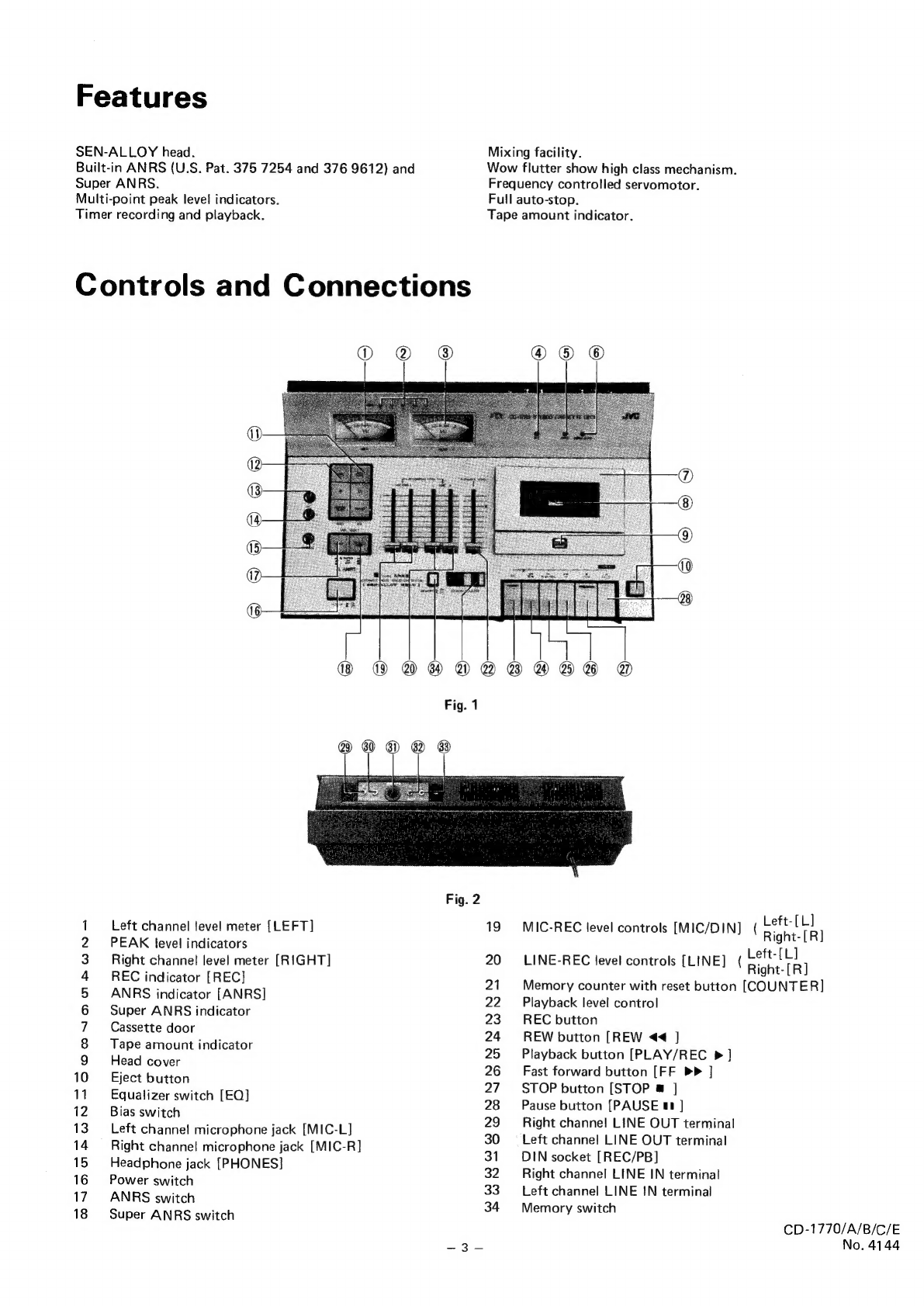
Controls
and
Connections
............0000000e008
3
Main
Parts
Removing..............2000eeeeeees
4
Enclosure
Assembly
..........000cc
ce
eeeeues
4
Electrical
Parts
2.5.02.
ic
uiweeeke
dew
en's
6
5
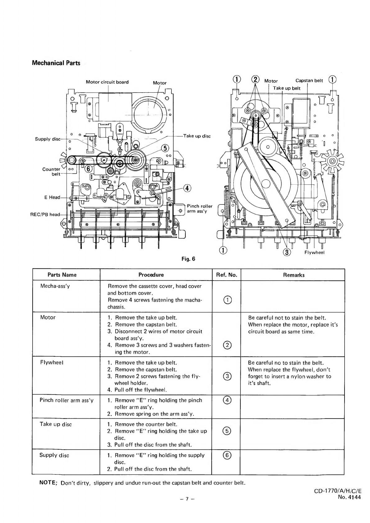
Mechanical
Parts
..............0000
cece
eeees
6
Main
Adjustments
...........
2.00
c
eee
eee
eens
7
Trouble
Shooting
Guide
..............
00
eee
eeee
12
Maintenance
..........
2...
cc
cece
eee
eee
ees
13
Block
Diagram...
0.2...
...
ccc
eee
eens
14
Specifications
Type
Stereo
cassette
deck
Track
system
4-track,
2-channel
Cassettes
C-30,
C-60,
C-90
Frequency
response
:
Signal-to-Noise
ratio
:
Effect
of
Super
ANRS
Improvement
of
S/N
:
Improvement
of
fre-
quency
response
:
Imrpovement
of
distortion
Wow
and
flutter
Crosstalk
Harmonic
distortion
:
Bias
z
Chrome
*1
20
—
18,000Hz
(Nominal)
30
—
16,000Hz
(Typical)
Regular
*2
20
—
17,000Hz
(Nominal)
30
—
15,000Hz
(Typical)
Supasses
DIN
45500
*1
TP-18
or
Equivalent
*2
QP-12
or
Equivalent
56dB(JIS)
The
S/N
is
improved
by
5dB
at
1kHz
and
by
10dB
above
5kHz
with
ANRS
on
62dB
with
ANRS
(DIN45500
weighted)
(normal
tape)
the
same
as
with
ANRS
OVU
recording;
6dB
at
10kHz
+5VU
recording;
12dB
at
10kHz
OVU
recording;
3%
less
at
10kHz
0.05%
(WRMS)
0.18%
(DIN45500)
65dB
1.2%
(normal
tape)
AC
bias
(95kHz)
Page
Wiring
S622
Hit
eta
bt
aioe
Se
aie
te
15
Standard
Schematic
Diagram...............20005
16
Circuit
Board
Parts
............02
cece
eee
eeeee
18
Main
Amp
Circuit
Board.
...........
0000
cca
ee
18
ANRS
Circuit
Board
...............00000euee
22
Switch
Circuit
Board
..........
00000
e
ences
24
Mechanical
Component
..............00000eeeas
26
Enclosure
Ass’y
and
Electrical
Parts
except
Circuit
Board
Parts
.............0.0000.
32
ACCOSSOFICS
65
a
oie
cisie-bhe
aWewcs
ainate
o
Pree
che
ates
34
Pack
ing
220i
esavaretag
ates
GA
ato
iis
Ge
ahs
Ae
a
35
Erasure
AC
erasure
Heads
Recording/playback
Motor
Tape
speed
Recording
time
Fast
forward
time
Rewind
time
Semiconductors
Input
jacks
Output
jacks
Power
requirement
Power
consumption
:
=
Sen-Alloy
head
Erasure
=
Ferrite
head
Frequency
control
DC
servomotor
4.8cm/sec
2
x
30
minutes
with
C-60
cassette
75sec
with
C-60
cassette
75sec
with
C-60
cassette
6
ICs
40
transistors
2
SCR
and
30
diodes
MIC
jack
x
2
Max.
sensitivity
0.2mV
Matching
impedance
6002
Input
jack
x
2
Min,
input
level
78mV
Input
impedance
1002
Output
jack
x
2
Output
level
0~
0.5V
Output
impedance
10k
Matching
load
impedance
6.8ka
or
more
Headphone
jack
x
1
Output
level
0.3mV
Matching
impedance
6.8k9
or
more
AC
120V,
60Hz
(CD-1770/C)
AC
240V,
50Hz
(CD-1770A/B)
AC
220V,
50Hz
(CD-1770E)
30W
Dimensions
Width
16-1/2"'
(420mm)
Height
3-1/2’
(
88mm)
Depth
10-7/8”"
(277mm)
Weight
12.1
Ibs
(5.5
kg)
Design
and
specifications
are
subject
to
change
without
notice.
CD-1770/A/B/C/E
a
ee
m
No.
4144