DTP900/DTP901/DTP902
4
DTP900 PARTS LIST(パーツリスト)
※1: “Environmental protection period mark label (WK53580)” and “Manufacture year/month label (WK75290)” are attached to the Pad of the desti-
nation “O” (for Chinese market).
※1: O 仕向 (中国仕向 )には、PAD 本体に環保期限マークラベル (WK53580)と製造年月ラベル (WK75290)が付加されています。
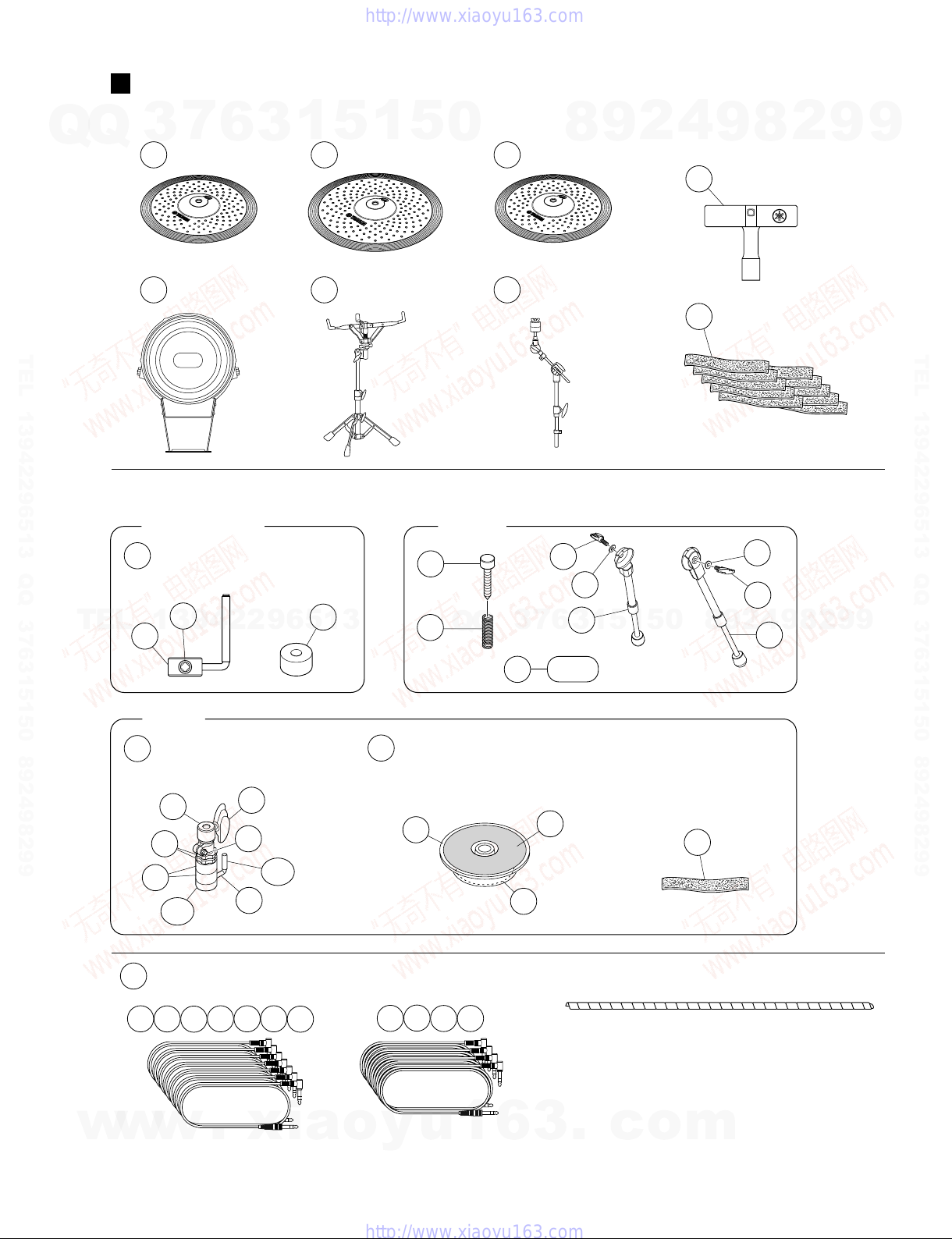
-- COMPLETE ASSEMBLY 同梱品セット
DTP900 (WR85880)
-- COMPLETE ASSEMBLY 同梱品セット
DTP900 O (WR90740)
10 -- OVERALL ASSEMBLY 総組立
PCY135 (WK36820) 2
20 -- OVERALL ASSEMBLY 総組立
PCY155 (WK72280)
30 -- OVERALL ASSEMBLY 総組立
RHH135 (WK37510)
40 -- OVERALL ASSEMBLY 総組立
KP125W (WR91030)
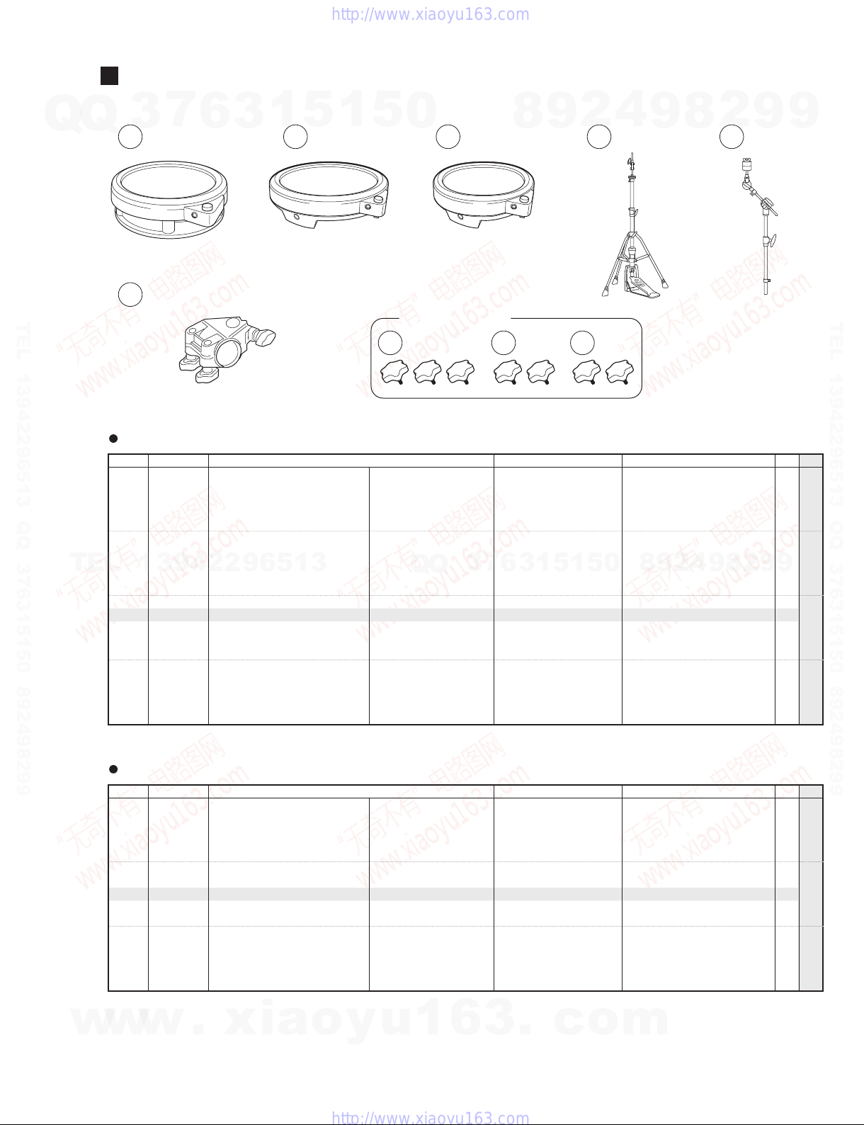
50 AAE96880 SNARE STAND スネアスタンドSS662 22
60 AAE96890 CYMBAL HOLDER シンバルホルダー CH750 2 20
70 -- CABLE SET SP ケーブルセットSP (WM79550)
140 WM962100 DRUM KEY 3 ドラムキー 3 05
200 V8234200 CABLE BAND ケーブル バンド 10 99
ACCESSORIES SET 付属品セット
A1 WK371500 ROT HOLD PARTS SET 回転ストッパセット PCY135/PCY155 3 07
A1a -- ROTATION HOLD PART 回り止め金具
(V857830)
A1b WM942400 BOLT 6.0X10 DRUM KEY 角ボルトM6X10 01
A1c WM813000 FELT WASHER D55X20T D55X18T フェルトワッシャー 03
A2 WK739000 CLUTCH SET DE 8F47 クラッチセットRHH135 10
A2a -- CLUTCH HEAD クラッチヘッド (WK37630)
A2b WK734800 ROT HOLD PARTS ASSEMBLY 回転ストッパ組立 08
A2ba -- ROT HOLD PARTS WELD 回転ストッパ溶接品 (WK73470)
A2bb WK738400 STOPPER CAP S BLACK ストッパキャップS 01
A2c WK377200 NUT 調整ナット 204
A2d WN784000 WING BOLT M6X9 ウィングボルト
A2e WN811400 DRUM KEY BOLT M6X12 角ボルトM6X12
A2f WK378200 FELT WASHER フェルトワッシャー 203
A3 WK378800 STAND BASE SET スタンドベースセット RHH135 09
A3a -- STAND BASE スタンドベース (WK37840)
A3b -- SLIP SHEET BLACK スリップシート (WK37850)
A3c -- CUSHION BLACK クッション
(WK40060)
A4 V8234200 CABLE BAND ケーブル バンドRHH135 99
A5 WM795100 WING BOLT L ウィングボルト(L)KP125W 2 05
A6 WM795300 BD LEG R RIGHT BD脚(8)−R集成 KP125W 11
A7 WM795400 BD LEG L LEFT BD脚(8)−L集成 KP125W 11
A8 WN553900 WASHER PLAIN KP125 8.0X16X1.0 MFZN2W3 平座みがき丸
KP125W 2 01
A9 WM027200 SPUR SPRING KP125 スパースプリング KP125W 2
A10 16033101 FP.HS STOPPER 2 FPHSストッパ2 KP125W 2 04
*A11 WR876100 RUBBER PAD PATCH W 打面パッチW
KP125W
-- CABLE SET SP ケーブルセットSP (WM79550)
C1 WN547000 SNARE CABLE 2.5 m STEREO PHONE スネアケーブル 07
C2 WN547200 TOM1 CABLE 2.5 m STEREO PHONE タム1ケーブル 07
C3 WN547300 TOM2 CABLE 2.5 m STEREO PHONE タム2ケーブル 07
C4 WN547400 TOM3 CABLE 4.0 m STEREO PHONE タム3ケーブル 08
C5 WN547500 TOM4 CABLE 4.0 m STEREO PHONE タム4ケーブル 08
C6 WN547600 RIDE CABLE 4.0 m STEREO PHONE ライドケーブル 08
C7 WN547700 CRASH1 CABLE 2.5 m STEREO PHONE クラッシュ1ケーブル 07
C8 WN547800 CRASH2 CABLE 4.0 m STEREO PHONE クラッシュ2ケーブル 07
C9 WN547900 HI HAT CABLE 2.5 m STEREO PHONE ハイハットケーブル 07
C10 WN548000 HH CON CABLE 2.5 m STEREO PHONE HHCONケーブル 07
C11 WN548100 KICK CABLE 2.5 m STEREO PHONE キックケーブル 07
REF NO. PART NO. DESCRIPTION 部品名 REMARKS QTY
RANK
*: New Parts RANK: Japan only
w
w
w
.
x
i
a
o
y
u
1
6
3
.
c
o
m
Q
Q
3
7
6
3
1
5
1
5
0
9
9
2
8
9
4
2
9
8
T
E
L
1
3
9
4
2
2
9
6
5
1
3
9
9
2
8
9
4
2
9
8
0
5
1
5
1
3
6
7
3
Q
Q
TEL 13942296513 QQ 376315150 892498299
TEL 13942296513 QQ 376315150 892498299
http://www.xiaoyu163.com
http://www.xiaoyu163.com