manuals.online logo
Brands
  1. Home
  2. •
  3. Brands
  4. •
  5. Yamaha
  6. •
  7. Inverter
  8. •
  9. Yamaha MU128 User manual

Yamaha MU128 User manual

SERVICE MANUAL
SY 011451 HAMAMATSU,JAPAN
0.32K-5351 I Printed in Japan’98.12
CONTENTS
PANEL LAYOUT........................................................................................3
SPECIFICATIONS .....................................................................................4
CIRCUIT BOARD LAYOUT .......................................................................6
WIRING & BLOCK DIAGRAM..................................................................7
DISASSEMBLY PROCEDURE.................................................................8
CIRCUIT BOARDS.................................................................................11
LSI PIN DESCRIPTION.........................................................................13
IC BLOCK DIAGRAM ............................................................................15
TEST PROGRAM...................................................................................18
INITIALIZE...............................................................................................26
ERROR MESSAGES ..............................................................................28
CONNECTING CABLES ........................................................................29
MIDI IMPLEMENTATION CHART .........................................................30
PARTS LIST
OVERALL CIRCUIT DIAGRAM
MU128
IMPORTANT NOTICE
This manual has been provided for the use of authorized Yamaha Retailers and their service personnel. It has been assumed that
basic service procedures inherent to the industry, and more specifically Yamaha Products, are already known and understood by
the users, and have therefore not been restated.
WARNING: Failure to follow appropriate service and safety procedures when servicing this product may result in
personal injury, destruction of expensive components and failure of the product to per form as specified.
For these reasons, we advise all Yamaha product owners that all service required should be performed by
an authorized Yamaha Retailer or the appointed service representative.
IMPORTANT: This presentation or sale of this manual to any individual or firm does not constitute authorization, certifica-
tion, recognition of any applicable technical capabilities, or establish a principal-agent relationship of any
form.
The data provided is believed to be accurate and applicable to the unit(s) indicated on the cover. The research engineering, and
service departments of Yamaha are continually striving to improve Yamaha products. Modifications are, therefor, inevitable and
changes in specification are subject to change without notice or obligation to retrofit. Should any discrepancy appear to exist,
please contact the distributor's Service Division.
WARNING: Static discharges can destroy expensive components. Discharge any static electricity you body may have
accumulated by grounding yourself to the ground buss in the unit (heavy gauge black wires connect to this
buss).
IMPORTANT: Turn the unit OFF during disassembly and parts replacement. Recheck all work before you apply power to
the unit.
WARNING: CHEMICAL CONTENT NOTICE!
The solder used in the production of this product contains LEAD. In addition, other electrical / electronic and / or plastic (where
applicable) components may also contain traces of chemicals found by the California Health and Welfare Agency (and possibly
other entities) to cause cancer and / or birth defects or other reproductive harm.
DO NOT PLACE SOLDER, ELECTRICAL / ELECTRONIC OR PLASTIC COMPONENTS IN YOUR MOUTH FOR ANY REASON
WHAT SO EVER!
Avoid prolonged, unprotected contact between solder and your skin! When soldering, do not inhale solder fumes or expose eyes to
solder / flux vapor!
If you come in contact with solder or components located inside the enclosure of this product, wash your hands before handling
food.
LUTHIUM BATTERY HANDLING
This product uses a lithium battery for memory back-up.
WARNING: Lithium batteries are dangerous because they can be exploded by improper handling. Observe the follow-
ing precautions when handling or replacing lithium batteries.
=Leave lithium battery replacement to qualified service personnel.
=Always replace with batteries of the same type.
=When installing on the PC board by soldering, solder using the connection terminals provided on the battery cells.
Never solder directly to the cells. perform the soldering as quickly as possible.
=Never reverse the battery polarities when installing.
=Do not short the batteries.
=Do not attempt to recharge these batteries.
=Do not disassemble the batteries.
=Never heat batteries or throw them into fire.
ADVARSEL!
Lithiumbatteri—Eksplosionsfare ved fejlagtig håndtering. Udskiftning må kun ske med batteri af samme fabrikat og type. Levér
det brugte batteri tilbage til leverandoren.
VARNING
Explosionsfara vid felaktigt batteribyte. Använd samma batterityp eller en ekvivalent typ som rekommenderas av
apparattillverkaren. Kassera använt batteri enlight fabrikantens instruktion.
VAROITUS
Paristo voi räjähtää, jos se on virheellisesti asennettu. Vaihda paristo ainoastaan laitevalmistajan suosittelemaan tyyppiin. Hävitä
käytetty paristo valmistajan ohjeiden mukaisesti.
The following information complies with Dutch Official Gazette 1995. 45; ESSENTIALS OF ORDER ON THE COLLECTION OF
BATTERIES.
=Please refer to the diassembly procedure for the removal of Back-up Battery.
=Leest u voor het verwijderen van de backup batterij deze beschrijving.
WARNING
Components having special characteristics are marked and must be replaced with parts having specification equal to those originally
installed.
2

MU128
3
1. A/D INPUT1,2 jacks
2. A/D INPUT VOLUME control
3. VOLUME control
4. STAND BY/ON switch (Power Switch)
5. MIDI IN A (front panel)
6. PHONES jack
7. Voice Category buttons
8. MODE button
9. PLAY button
0. EDITbutton
A. UTIL(UTILITY)button
B. EFFECT button
C. EQ button
D. MUTE/SOLO button
E. ENTERbutton
F. EXITbutton
G. PART / buttons
H. SELECT / buttons
I. VALUE / buttons
J. Data dial
K. SELECT button
L. PART GROUP button
M. Display
N. LEDs
1. MIDI terminals
2. HOST SELECT switch
3. TO HOST terminals
4. DC IN terminals
5. Power cord hook
6. OUTPUT L,R jacks (Left,Right)
7. INPUT L,R jacks (Left,Right)
8. XG Plug-in board expansion bay
lFront Panel
lRearPanel
MU128
4
1. FUNCTION
Tone generation Method AWM2 (Advanced Wave Memory 2)
Maximum Simultaneous Polyphony 128-note
Sound Module Modes XG, TG300B and Performance
Multi-timbral Capacity 64-part (on 64 MIDI channels; with dynamic Voice allocation)
Effects Seven sections of multi-effects: Reverb(12 Types), Chorus(14
Types),Variation (70 Types), Insertion 1/2 (43 Types),Multi EQ(4 Types),
and Part EQ (1 Type)
Interface Direct connection to host computer port (RS-232C,RS-422); MIDI terminals
allow connection to MIDI sequencer or MIDI controller.
2. COMPONENT
Internal Voice Normal Voice Total 1342
XG 1099
TG300B 664
Drum Voice Total 47
XG 37
TG300B 10
Perfomance Programs Up to four Voices plus all effect settings can be memorized to a Performance.
Preset Programs 100
User Programs 100
Effects Reverb 12 Types
Chorus 14 Types
Variation 70 Types
Insertion 1/2 43 Types
Multi EQ 5 Types
3. DISPLAY
LCD Custom back-lit LCD
LED 10
4. CONTROLS
[PLAY] [UTIL] [MODE]
[EDIT] [EFFECT] [EQ]
[MUTE/SOLO] [ENTER] [EXIT]
[PART ] [PART ]
[SELECT ] [SELECT ]
[VALUE ] [VALUE ]
HOST SELECT
STANDBY/ON
VOLUME
A/D INPUT VOLUME
[SELECT] [PART GROUP]
[Piano][Chrom.perc.][Organ][Guitar][Bass][Strings][Ensemble][Brass][Reed][Pipe][Synth lead]
[Synth pad][Synth effects][Ethnic][Percussive][SFX][Model excl.][Drum]
MU128
5
5. JACKS andTERMINALS
Front panel:PHONES jack (stereo mini pin), A/D INPUT 1, 2, jacks (1/4” mono), MIDI IN-A terminal
Rear panel:INPUT L, R jacks (Left,Right), OUTPUT L, R jacks (Left,Right), DC IN jack, TO HOST terminal, HOST
SELECT switch, MIDI IN-A/B, MIDI OUT, and MIDI THRU terminals, XG Plug-in board expansion bay
6. POWER SUPPLY
Yamaha PA-6 AC Adaptor (included)
7. DIMENSIONS (W XDXH)
219.5(W)X229.5(D)X91.1(H)[mm] (8-5/8"X9"X3-1/2")
8. WEIGHT
1.9Kg(4 lbs., 3 oz.)
9. SUPPLIED ACCESSORIES
Owner’s Manual, Sound List Book & MIDI Data Book
AC Adaptor (PA-6)
CD-ROM(XG tools)
10. OPTIONALACCESSORIES
XG Plug-in board
Virtual Acoustic Plug-in Board PLG100-VL
Vocal Harmony Plug-in Board PLG100-VH
Advanced DX/TX Plug-in Board PLG100-DX
11. OUTPUT LEVEL
Refer to the TEST 14 &15 of the "TEST PROGRAM" on page 22 & 23.
MU128
6
CN1
CN2
CN4
CN9
CN5
CN6
CN7
CN8
CN10
CN12
CN11
CN13
2NC-V248430
(Rear)
lBottom View
lFrontView
(Front)
77
77
7
MU128MU128
MU128MU128
MU128
28C99-8812612
LCD
28CA1-8812501
MU128MU128
MU128MU128
MU128
88
88
8
1. Bottom Assembly
1-1 Remove the four (4) screws marked [60], the two
(2) screws marked [70] and the two (2) screws
marked [80]. The bottom assembly can then be
removed. (Fig. 1)
[60]: Bind Head Tapping Screw-B 3.0X8 MFNI33 (VF646900)
[70]: Bind Head Tapping Screw-B 3.0X6 MFZN2BL (EP600230)
[80]: Flat Head Tapping Screw-C 3.0X8 MFNI33 (V2500600)
(Fig. 1)
2. Top Assembly
2-1 Remove the bottom assembly. (See Procedure 1.)
2-2 Remove the A/D INPUT knob.
2-3 Remove the two (2) screws marked [30]. The
Top Assembly can then be removed. (Fig. 2)
*When assembling the bottom assembly,
tighten the screws in the order shown in the
figure below.
(Fig. 2)
3. DM Circuit Board and ADVR1 Circuit Board
3-1 Remove the bottom assembly. (See Procedure 1.)
3-2 Remove the Top assembly. (See Procedure 2.)
3-3 Remove the four(4) screws marked [T40a]. The DM
circuit board can then be removed. (Fig. 3)
3-4 Remove the two(2) screws marked [T40b]. The
ADVR1 circuit board can then be removed. (Fig. 3)
[30]: Flat Head Tapping Screw-C 3.0X8 MFNI33 (V2500600) [T40]: Bind Head Tapping Screw-B 3.0X6 MFZN2BL (EP600230)
(Fig. 3)
(Bottom Veiw)
(Top View)
(Front) (Rear)
(Rear View)
(Bottom) (Top)
(Bottom View)
(Front)
(Front)
(Rear)
(Rear)
5. PSW Connector Assembly, PMD Circuit Board and ADMVR2 Circuit Board
4. LEDSW1 Circuit Board and LEDSW2 Circuit Board and LCD and RE Circuit Board
(Fig. 5)
(Fig. 4)
4-1 Remove the bottom assembly. (See Procedure 1.)
4-2 Remove the two (2) screws marked [30]. The front
assembly can then be removed. (Fig. 2)
4-3 Remove the five (5) screws marked [100]. The
LEDSW1circuitboard can then be removed.(Fig.4)
4-4 Remove the four (4) screws marked [80A]. The
LEDSW2 circuit board can then be removed. (Fig. 4)
4-5 Removethefour(4)screwsmarked[80B].TheLED
can then be removed. (Fig. 4)
4-6 Remove the two (2) screws marked [120] and the
encoder knob. The RE circuit board can then be
[40]: Bind Head Tapping Screw-B 3.0X6 MFZN2BL (EP600230)
[50]: Bind Head Tapping Screw-B 2.6X10 MFZN2Y (VD791000)
[80]: Bind Head Tapping Screw-B 2.6X10 MFZN2Y (VD791000)
[20d]: Bind Head Tapping Screw-B 2.6X6 MFZN2Y (VC069600)
(INSIDE VIEW)
*Connection of the cable bundles to the CN9
of the DM circuit board is shown in Fig 6-1.
(Fig. 6-1)
[100]: Bind Head Tapping Screw-B 2.6X6 MFZN2Y (VC069600)
[120]: Bind Head Tapping Screw-B 3.0X6 MFZN2BL (EP600230)
(Fig. 6-2)
Front Assembly
*Be careful not to injure your
fingers for the sharp edge
of the rear shield.
5-1 Remove the bottom assembly. (See Procedure 1.)
5-2 Remove the front assembly. (See Procedure 4-2.)
5-3 Removethevolume knob.
5-4 Remove the two (2) screws marked [40] and the
screw marked [50]. The PSW connector assem-
bly and the JACK assembly can then be removed.
(Fig. 4)
5-5 Remove the two (2) screws marked [20d]. The PMD
circuit board, the ADMVR2 circuit board and the front
shield can then be removed. (Fig. 5)
5-6 Remove the front shield marked [50] from the PMD
circuit board. (Fig. 5)
3-5 Melt the solder on the four(4) points marked [A] in
figure 6-2 and remove the rear shield. (Fig. 3)
removed. (Fig. 4)
MU128
9
lInstalling the Plug-in Board
1. Turn off the power switches of the MU128 and any connected devices. Also remove all connected cables
from the MU128, and unplug the power adaptor.
lWhen installing/uninstalling an XG Plug-in board, make sure to let the installed board(s) cool down for a while after
turning the power switch off.
lMake sure to unplug the power adaptor from the MU128 before installing/uninstalling the board. Attempting to install/
uninstall the board while power adaptor is still connected may damage the board and/or the MU128.
2. Remove the large screw from the expansion bay cover on the rear panel, and remove the cover (as shown
below).
lSince the screw is tightened securely at the factory, you may need to use a screwdriver to loosen it at first,
so that it can be fastened and removed simply by using your fingers.
3. Remove the XG Plug-in board from its protective packaging.
Before handling the XG Plug-in board, make sure to discharge any static electricity from your body or clothes by
touching a grounded metal surface. Also be careful not to touch any parts or connectors of the board.
4. Insert the board along the guide rails about two-thirds of the way inside the MU128, with the connector side
face down and toward you (as shown below). Make sure to insert it slowly and gently, keeping the edges of
the board inside the proper guide rails, as shown in the illustration. With keeping the board in place, plug in
one of the three cable connectors to the connector on the XG Plug-in board. Any one of the cable connectors
can be used.
Thelogicalboard assignment in theMU128(PLG-1 -3) is setautomatically to the following order:1) PLG100-
VL, 2) PLG100-DX, 3) PLG100-VH.
MU128
10
Carefully plug in the cable connector to the XG Plug-in connector as shown below, matching the two notches
on the cable connector with the sockets on the board. Firmly press the connectors together until they lock.
5. Slowly and gently insert the rest of the XG Plug-in board into the expansion bay.
6. Replace the cover with the screw you removed in step #2.
Latch the hinges on the cover to the inside of the expansion bay and secure the cover to the rear panel with
the screw. Press the cover down with your hand for the sponge cushion on the back of the cover to hold the
installed board(s) securely in place.
MIDI
THRU OUT IN-A IN-B
HOST SELECT
MIDI
Mac
PC-2 PC-1
TO HOST DC IN
OUTPUT INPUT
L
R
SER NO.
MIDI
THRU OUT IN-A IN-B
HOST SELECT
MIDI
Mac
PC-2 PC-1
TO HOST DC IN
OUTPUT INPUT
L
R
SER NO.
11
MU128MU128
MU128MU128
MU128
•
DM Circuit Board
Component side Pattern side
MIDI
THRU OUT IN-A IN-B HOSTSELECT TO HOST DC-IN OUTPUT
L/R INPUT
L/R
toPMD-CN1
CN2 :
CN9 :
to LEDSW1-CN8
to LEDSW1-CN10
CN8 :
to LEDSW2-CN3
CN6 :
to RE-CN9
CN1,4,5 :
to Plug in board
to LCD
CN7 :
CN13 :
to Power SW Assembly
CN11 :
toPMD-CN2
CN12 :
to ADMVR2-CN5
CN10 :
to ADVR1-CN7
2NA1-V227130 Note : See parts list for details of circuit board component parts.
=Connection of the cable bundles to the
CN9 of the DM circuit board is shown right.
0
MU128MU128
MU128MU128
MU128
12
•
LEDSW1 Circuit Board
PART GROUP
toDM-CN9
EDIT
EFECT
EQ
PLAY
UTIL
MODE
MUTE/
SOLO
ENTER
EXIT
PART
-PART
+
SELECT
VALUE
+
VALUE
-
SELECT
toDM-CN9
SELECT
Component side Synth effects Ethnic Percusive SFX Model excl. Drum
Ensemble Brass Reed Pipe Synth lead Synth pad
Piano Chrom.perc. Organ Guitar Bass Strings
MU PLG-1 PLG-2 PLG-3toDM-CN8
Component side
Pattern side
•
LEDSW2 Circuit Board
A/DINPUT
•
ADVR1 Circuit Board
1
toDM-CN10
to ADMVR2-CN4
Component side
Pattern side
2
•
ADMVR2 Circuit Board
VOLUME
Component side
Pattern side Pattern side
Component side
•
PMD Circuit Board
•
RE Circuit Board
toDM-CN11
toDM-CN2
PHONES MIDI IN A
toDM-CN6
(Dial)
Component side Pattern side
Note : See parts list for details of circuit board component parts.
2NA1-V227140
toDM-CN12
to ADVR1-CN6
Pattern side
2
MU128
13
=
==
=HD6437043E00F (XS936A00) CPU
PIN
NO. NAME I/O FUNCTION PIN
NO. NAME I/O FUNCTION
1 /WRHH O HH write 73 D15 I/O
2 PE14 I/O Port E 74 D14 I/O Data bus
3/WRHL O NC 75 D13 I/O
4 PA21 I Flash/WE write check (RY/BY) 76 D12 I/O
5 PE15 I/O LCD, SW, LED Data control (DB7) 77 VCC - Power supply
6 VSS I Ground 78 D11 I/O Data bus
7 A0 O 79 VSS - Ground
8A1 O 80D10I/O
9A2 OAddressbus 81D9I/O
10 A3 O 82 D8 I/O Data bus
11A4 O 83D7I/O
12 VCC - Power supply 84 D6 I/O
13 A5 O Address bus 85 VCC - Power supply
14 VSS - Ground 86 D5 I/O Data bus
15 A6 O 87 VSS - Ground
16A7 O 88D4I/O
17A8 O 89D3I/O
18 A9 O 90 D2 I/O Data bus
19 A10 O 91 D1 I/O
20 A11 O Address bus 92 D0 I/O
21 A12 O 93 VSS - Ground
22 A13 O 94 XTAL - Crystal oscillator
23 A14 O 95 MD3 - Mode select
24 A15 O 96 EXTAL - Crystal oscillator
25 A16 O 97 MD2 - Mode select
26 VCC - Power supply 98 NMI - Non-maskable interrupt
27 A17 O Address bus 99 VCC - Power supply
28 VSS - Ground 100 PA16 I Rotary encoder (REB)
29 PA20 O LED control 101 PA17 I Rotary encoder (REA)
30 PA19 O NC 102 MD1 - Mode select
31 PB2 O PB select (SW1) 103 MD0 - Mode select
32 PB3 O PB select (SW2) 104 PLLVCC - PLL power supply
33 PA18 O SW data read (SWD) 105 PLLCAP - PLL capacitor
34 PB4 O PB select (SW3) 106 PLLVSS - PLL ground
35 VSS - Ground 107 PA15 O Rotary encoder (RER)
36 PB5 O PB select (SW4) 108 /RES - Reset
37 A18 O 109 PE0 O LCD control (LCD-R/W)
38 A19 O Address bus 110 PE1 O NC
39 A20 O 111 PE2 O LCD control (LCD-RS)
40 VCC - Power supply 112 VCC - Power supply
41 A21 O Address bus 113 PE3 O Latch for reset (LCREAD)
42 VSS - Ground 114 PE4 O LCD control (LCD-E)
43 /RD O Read 115 PE5 O 1M clock for mac.
44 /WDTOVF - NC 116 PE6 O Clock for PB serial (SICLK)
45 D31 I/O Data bus 117 VSS - Ground
46 D30 I/O Data bus 118 AN0 I A/D input level (R)
47 /WRH O High write 119 AN1 I
48 /WRL O Low write 120 AN2 I A/D input level (L)
49 /CS1 O Chip select for SRAM 121 AN3 I A/D jack check
50 /CS0 O Chip select for system Rom 122 AN4 I Host sw position
51 PA9 O PB select (SW6) 123 AN5 I Off-line detection
52 PA8 O PB select (SW5) 124 AVSS - Analog ground
53 /CS3 O Chip select for serial interface 125 AN6 I Battery check
54 /CS2 O Chip select for SWP30 126 AN7 I Model check
55 VSS - Ground 127 AVREF I A/D refference voltage
56 D29 I/O 128 AVCC I Analog power supply
57 D28 I/O 129 VSS - Ground
58 D27 I/O Data bus 130 RXD0 I MIDI-IN
59 D26 I/O 131 TXD0 MIDI-OUT
60 D25 I/O 132 /IRQ0 I Serial ready for PB
61 VSS - Ground 133 RXD1 I MIDI-IN
62 D24 I/O Data bus 134 TXD1 O MIDI-OUT
63 VCC - Power supply 135 VCC - Power supply
64 D23 I/O 136 PA5 O MIDI-IN A front/rear select
65 D22 I/O 137 PE7 O SW storobe (SWS)
66 D21 I/O 138 PE8 I/O LCD, SW, LED data control (DB0)
67 D20 I/O Data bus 139 PE9 I/O LCD, SW, LED data control (DB1)
68 D19 I/O 140 PE10 I/O LCD, SW, LED data control (DB2)
69 D18 I/O 141 VSS - Ground
70 D17 I/O 142 PE11 I/O LCD, SW, LED data control (DB3)
71 VSS - Ground 143 PE12 I/O LCD, SW, LED data control (DB4)
72 D16 I/O Data bus 144 PE13 I/O LCD, SW, LED data control (DB5)
MU128
14
=
==
=TC203C760HF-002 (XS725A00) SWP30B (AWM Tone Generator coped with MEG) Standard Wave Processor
PIN
NO. NAME I/O FUNCTION PIN
NO. NAME I/O FUNCTION
1 Vss (Ground) 121 VSS (Ground)
2
CA0 I
122
HMD0
I/O
3 CA1 I 123 HMD1 I/O
4
CA2 I
124
HMD2
I/O
5 CA3 I 125 HMD3 I/O
6
CA4 I
126
HMD4
I/O
7
CA5 I Address bus of internal register
127
HMD5
I/O
8 CA6 I 128 HMD6 I/O Wave memory data bus (Upper 16 bits)
9
CA7 I
129
HMD7
I/O
10 CA8 I 130 HMD8 I/O
11
CA9 I
131
HMD9
I/O
12
CA10 I
132
HMD10
I/O
13 CA11 I 133 HMD11 I/O
14
VSS (Ground)
134
HMD12
I/O
15 CD0 I/O 135 HMD13 I/O
16
CD1
I/O
136
HMD14
I/O
17
CD2
I/O
137
HMD15
I/O
18 CD3 I/O 138 VSS (Ground)
19
CD4
I/O
139
HMA0
O
20 CD5 I/O 140 HMA1 O
21
CD6
I/O
141
HMA2
O
22
CD7
I/O
142
HMA3
O
23 CD8 I/O Data bus of internal register 143 HMA4 O
24
CD9
I/O
144
HMA5
O
25 CD10 I/O 145 HMA6 O
26
CD11
I/O
146
HMA7
O
27
CD12
I/O
147
HMA8
O
28 CD13 I/O 148 HMA9 O
29
CD14
I/O
149
HMA10
O
30 VDD (Power supply) 150 VDD (Power supply)
31 VSS (Ground) 151 VSS (Ground)
32
CD15
I/O
152
HMA11
O
33 CSN I Chip select 153 HMA12 O Wave memory address bus
34
WRN I Write strobe
154
HMA13
O
35 RDN I Read strobe 155 HMA14 O
36 VDD (Power supply) 156 HMA15 O
37
SYSH0
O
157
HMA16
O
38 SYSH1 O 158 HMA17 O
39
SYSH2
O
159
HMA18
O
40 SYSH3 O NSYS/LNSYS upper 16 bits output 160 HMA19 O
41 SYSH4 O 161 HMA20 O
42
SYSH5
O
162
HMA21
O
43 SYSH6 O 163 HMA22 O
44
SYSH7
O
164
HMA23
O
45 KONO0 O 165 HMA24 O
46 KONO1 O Key on data 166 VSS (Ground)
47
KONO2
O
167
MRASN
O
RAS when DRAM(s) is connected to wave memory
48 KONO3 O 168 MCASN O CAS when DRAM(s) is connected to wave memory
49
VSS (Ground)
169
MOEN
O
Wave memory output enable
50 SYSL0 I/O 170 MWEN O Wave memory write enable
51 SYSL1 I/O 171 VSS (Ground)
52
SYSL2
I/O
172
LMD0
I/O
53 SYSL3 I/O NSYS input/LNSYS output lower 8 bits 173 LMD1 I/O
54
SYSL4
I/O
174
LMD2
I/O
55 SYSL5 I/O 175 LMD3 I/O
56 SYSL6 I/O 176 LMD4 I/O
57
SYSL7
I/O
177
LMD5
I/O
58 KONI0 I 178 LMD6 I/O
59
KONI1 I Key on data input
179
LMD7
I/O
Wave memory data bus (Lower 16 bits)
60 VDD I (Power supply) 180 VDD (Power supply)
61 VSS (Ground) 181 VSS (Ground)
62
KONI2 I
182
LMD8
I/O
63 KONI3 I 183 LMD9 I/O
64
DAC0
O
DAC output
184
LMD10
I/O
65 DAC1 O 185 LMD11 I/O
66 WCLK O DAC0/DAC1 word clock 186 LMD12 I/O
67
MELO0
O
187
LMD13
I/O
68 MELO1 O 188 LMD14 I/O
69
MELO2
O
189
LMD15
I/O
70 MELO3 O MEL wave data output 190 VSS (Ground)
71 MELO4 O 191 LMA0 O
72
MELO5
O
192
LMA1
O
73 MELO6 O 193 LMA2 O
74
MELO7
O
194
LMA3
O
75 VDD (Power supply) 195 LMA4 O
76 ADLR O ADC word clock 196 LMA5 O
77
MELI0 I
197
LMA6
O
78 MELI1 I 198 LMA7 O
79
MELI2 I
199
LMA8
O
80 MELI3 I MEL wave data input 200 LMA9 O
81 MELI4 I 201 LMA10 O
82
MELI5 I
202
LMA11
O
83 MELI6 I 203 VSS (Ground)
84
MELI7 I
204
LMA12
O
85 VSS (Ground) 205 LMA13 O Wave memory address bus (Lower data memory)
86 RCASN O DRAM column address strobe (RAS signal) 206 LMA14 O
87
RA8
O
207
LMA15
O
88 RA7 O 208 LMA16 O
89
RA6
O
209
LMA17
O
90 VDD (Power supply) 210 VDD (Power supply)
91 VSS (Ground) 211 VSS (Ground)
92
RA5
O
DRAM address bus
212
LMA18
O
93 RA4 O 213 LMA19 O
94
RA3
O
214
LMA20
O
95 RA2 O 215 LMA21 O
96 RA1 O 216 LMA22 O
97
RA0
O
217
LMA23
O
98 RRASN O DRAM row address strobe (RAS signal) 218 LMA24 O
99
RWEN
O
DARM write enable
219
VSS (Ground)
100 VSS (Ground) 220 SYO O Sync.signal for master clock
101 RD7 I/O 221 SYOD O Sync. signal for HCLK/QCLK
102
RD6
I/O
222
QCLK
O
1/12 master clock (64Fs)
103 RD5 I/O 223 HCLK O 1/6 master clock (128Fs)
104
RD4
I/O
224
CK256
O
1/3 master clock (256Fs)
105 RD3 I/O 225 SYSCLK O 1/2 master clock (384Fs)
106 RD2 I/O 226 VDD (Power supply)
107
RD1
I/O
227
SYI I Sync. clock
108 RD0 I/O 228 MCLKI I Master clock input
109
VSS (Ground)
229
MCLKO
O
Master clock output
110 RD17 I/O 230 VDD (Power supply)
111 RD16 I/O DRAM data bus 231 XIN I Crystal osc.input
112
RD15
I/O
232
XOUT
O
Crystal osc.output
113 RD14 I/O 233 VSS (Ground)
114
RD13
I/O
234
ICN I Initial clear
115 RD12 I/O 235 CHIP2 I 2 chips mode enable
116 RD11 I/O 236 SLAVE I Master/Slave select when 2 chips mode
117
RD10
I/O
237
TESTON I
118 RD9 I/O 238 ACIN I Test pin
119
RD8
I/O
239
DCTEST I
120 VDD (Power supply) 240 VDD (Power supply)
MU128
15
= m
mm
mPD63200GS-E1 (XP867A00) DAC (Digital to Analog Converter)
PIN
NO. NAME I/O FUNCTION PIN
NO. NAME I/O FUNCTION
1 4/8FS I 4/8 Fs selection 9 R. REF Channel R voltage reference
2 D. GND Digital ground 10 L. REF Channel L voltage reference
3 16/8 BIT I 16 bit/8 bit selection 11 L. OUT O Channel L output
4 D. VDD Digital power supply 12 A. GND Analog ground
5 A. GND Analog ground 13 LRCX/WD I Left/right check, Word clock
6 R. OUT O Channel R output 14 LR/RSI I Left/right selection, Channel R series input
7 A. VDD Analog power supply 15 SI/LSI I Series input/Channel L series input
8A.VDD 16 CLK I Clock
=
==
=m
mm
mPD71051GU-10-E2 (XS762A00) Serial Controller
PIN
NO. NAME I/O FUNCTION PIN
NO. NAME I/O FUNCTION
1 D2 I/O Data bus 15 TxRDY O Transmit ready
2 D3 I/O Data bus 16 SYNC/BRK I/O Synch. receiver/break
3 RxDATA I Receive data 17 /CTS I MODEM control
4 GND - Ground 18 TxEMP O Transmitter empty
5 D4 I/O 19 TxDATA O Transmit data
6 D5 I/O Data bus 20 CLK I Main clock
7D6I/O 21RESETI Reset
8D7I/O 22/DSRI
9 /TxCLK I Transmitter clock 23 /RTS O MODEM control
10 /WR I Write control 24 /DTR O
11 /CS I Chip select 25 /RxCLK I Receive clock
12 C//D I 26 VDD - Power supply (+5V)
13 /RD I Read control 27 D0 I/O Data bus
14 RxRDY O Receive ready 28 D1 I/O Data bus
=PCM1800 (XU770A00) A/D Converter
PIN
NO. NAME I/O FUNCTION PIN
NO. NAME I/O FUNCTION
1 VINL I Analog input (L ch.) 13 LRCK I/O Sampling clock input/output
2 VREF1 Reference 1 decoupling cap. 14 BCK I/O Bit clock input/output
3 REFCOM Reference decoupling common 15 DOUT O Audio data output
4 VREF2 Reference 2 decoupling cap. 16 SYSCK I System clock input
5 VINR I Analog input (R ch.) 17 DGND Digital ground
6 RSTB I Reset input active “L” 18 VDD Power supply +5V
7 BYPAS I LCF bypass control 19 CINNR Anti-aliasing filter cap. (-) R ch.
8 FMT0 I Audio data format 0 20 CINPR Anti-aliasing filter cap. (+) R ch.
9 FMT1 I Audio data format 1 21 CINNL Anti-aliasing filter cap. (-) L ch.
10 MODE0 I Master/Slave mode selection 0 22 CINPL Anti-aliasing filter cap. (+) L ch.
11 MODE1 I Master/Slave mode selection 1 23 VCC Analog power supply
12 FSYNC I/O Frame sync. input/output 24 AGND Analog ground
MU128
16
MU128
17
MU128
18
Preparations
The following measuring instruments and jigs are
required for testing the equipment
Measuring instruments:
Low-frequency oscillator (Distortion factor:
0.1 % or less), Frequency counter,
Oscilloscope (Input impedance: 1 MÙor
more), Level meter (JIS-C curve), Analog
currugated analyzer, Keyboard amplifier
Jigs: MIDI cable, PB (plug-in board)
Test
number Test title
A TEST ENTRY
B STARTING THE TESTS
1 SRAM
2 BATTERY
3 LCD DOT BLINK AND CONTRAST
4 LED
5 SWITCHES
6 DIAL
7 MIDI 1 A Front
8 MIDI 2 A Rear
9 MIDI 3 B
10 MIDI 4
11 HOST SELECT
12 TO HOST
13 WAVE ROM
14
1 kHz OUTPUT (L) SIGNAL SOUND
15
1 kHz OUTPUT (R) SIGNAL SOUND
16 A/D INPUT HIGH
17 A/D INPUT LOW
18 SDP AND DRM
19
CHECKING THE 128 SIGNAL SOUNDS
20 PB1 NAME
21 PB1 RAM
22 PB1 MIDI IN
23 PB1 MEL
24 PB2 NAME
25 PB2 RAM
26 PB2 MIDI IN
27 PB2 MEL
28 PB3 NAME
29 PB3 RAM
30 PB3 MIDI IN
31 PB3 MEL
32 FACTORY SETTINGS
33 EXIT
Note 1: For tests 20 to 23, the plug-in board should be
connected to the CN5 of the DM sheet on the
equipment before turning ON the power supply.
Note 2: For tests 24 to 27, the plug-in board should be
connected to the CN4 of the DM sheet on the
equipment before turning ON the power supply.
Note 3: For tests 28 to 31, the plug-in board should be
connected to the CN1 of the DM sheet on the
equipment before turning ON the power supply.
The tests shown below need not be conducted as
part of the inspection of MU128.
21 PB1 RAM
25 PB2 RAM
29 PB3 RAM
A. TEST ENTRY
To turn ON the equipment, press the STAND BY/ON
button while pressing the PLAY and MUTE/SOLO
buttons at one time.
MU128 TEST MODE
Ver#.## ##-###-##
Ver #.## shows the version number of the product
program ROM.
Precautions before starting the test
Before starting a test immediately after the end of the
assembly or battery replacement, press STAND
BY/ON while pressing the UTIL and ENTER buttons
at one time. This step will change the inputted
values over to the factory settings.
B. Starting the tests
Press the SELECT / button and select the test
numbers desired. Then press the ENTER button. The
tests with their numbers selected will be then conducted
in sequence.
When the ENTER button is pressed without any test
numbers selected, the tests listed will be conducted in
numerical order, starting with the "1. SRAM " test.
When the test being conducted is finished without any
problems, ok will appear and the next test will be
conducted automatically. If the next test is not
conducted automatically, refer to "Ending the test" for
each item.
The screen for selecting the test number desired will be
indicated by pressing the EXIT button, whether the
equipment fails in the test being conducted or not.)
If an error occurs during the "5.SWITCHES" test,
however, refer to "Ending the test".
1. SRAM
01 RAM
Write/read the data in the SRAM field and check/verify
the data.
All the SRAM data will be saved.
Displaying the test result
OK 01 RAM
ok
NG 01 RAM
err
2. BATTERY
02 BATTERY
The battery voltage is checked by the A/D of the CPU (IC
21). Make sure that the voltage is in the range from 2.9
to 3.4 V.
Displaying the test result
OK 02 BATTERY
ok
MU128
19
NG 02 BATTERY
err
3. LCD DOT BLINK AND CONTRAST
Visually check to see if all of the white dots of the LCD
are highlighted black.
Also check to see if the back light is lit properly. Then
press the [SELECT] button and make sure that the
contrast is changed in eight stages.
Ending the test
Press the [ENTER] button. You will then go to the next
test.
4. LED
04 LED
Make sure that the LEDs are lit in order of [MU],
[PLG-1], [PLG-2], [PLG-3], [PLAY], [UTIL], [MODE],
[EDIT], [EFFECT], and [EQ]. Also make sure that
all of the LEDs are then lit and extinguished.
Ending the test
Press the [ENTER] button. You will then go to the
next test.
5. SWITCHES
05 SWITCH
[Piano]
[TURN ON/OFF] the panel switches from [Piano] to
[Value in] accordance with the switch name displayed
on the LCD.
When the above step is done, a specific sound is
heard if the switch being tested is in its normal condition.
You will then goto the test of the next switch.
If the switch being tested fails in the test, you will not
go to the test of the next switch even though you
press the switch directed on the LCD.
Displaying the test result
OK 05 SWITCH
ok
NG None
Ending the test
When the test of the switches from [Piano] to [Value ]
has been finished, you will go to the next test. If you
think that the switch being tested has fails in the test,
turn OFF the equipment once and restart the test.
6. DIAL
06 DIAL
Right 0-10=00
Make that the dial is working properly. Slowly turn the
dial clockwise until a value of 10 is obtained for "00"
on the LCD. When the value 10 is obtained, the next
item illustrated below will appear.
06 DIAL
Left 0-10=00
Slowly turn the dial counterclockwise until a value of
10 is obtained for "00" on the LCD.
Displaying the test result
OK 06 DIAL
ok
NG 06 DIAL
err
7. MIDI 1 A Front
Use a MIDI cable and connect the MIDI IN A (front)
connector to the MIDI OUT connector. Then conduct
the test.
Before starting the test, select MIDI under HOST
SELECT.
07 MIDI 1A Front
The test pattern (AA 50 5F) will be sent from MIDI
OUT and received by MIDI IN (front). The result of the
test pattern received will then be judged.
Displaying the test result
OK 07 MIDI 1A Front
ok
NG 07 MIDI 1A Front
err
8. MIDI 2 A Rear
Use a MIDI cable and connect the MIDI IN A (rear)
connector to the MIDI OUT connector. Then conduct
the test.
Before starting the test, select MIDI under HOST
SELECT.
08 MIDI 2A Rear
The test pattern (AA 50 5F) will be sent from MIDI
OUT and received by MIDI IN A (rear). The result
of the test pattern received will then be judged.
Displaying the test result
OK 08 MIDI 2A Rear
ok
NG 08 MIDI 2A Rear
err
MU128
20
9. MIDI 3 B
Use a MIDI cable and connect the MIDI IN B connector
to the MIDI OUT connector. Then perform the test.
Before starting the test, select MIDI under HOST SELECT.
09 MIDI 3 B
The test pattern (AA 50 5F) will be sent from MIDI
OUT and received by MIDI IN B. The result of the test
pattern received will then be judged.
Displaying the test result
OK 09 MIDI 3 B
ok
NG 09 MIDI 3 B
err
10. MIDI 4
Use two MIDI cables and connect the MIDI IN A (rear)
and MIDI IN B connectors to the MIDI OUT and MIDI
THRU connectors respectively. Then perform the test.
Before starting the test, select MIDI the HOST
SELECT.
10 MIDI 4
The test pattern (AA 50 5F) will be sent from MIDI
OUT and received by MIDI IN A. The data output from
MIDI THRU will be received by MIDI IN B. The result
of the test pattern and data received will be judged.
Displaying the test result
OK 10 MIDI 4
ok
NG 10 MIDI 4
err
11. HOST SELECT
11 HOST SELECT
Mac ZZZ-YYY= XXX
(ZZZ=Lower limit, YYY=Upperlimit, XX= Measured
value)
Change MAC over to PC-1, PC-2, and MIDI in
sequence under HOST SELECT in accordance with
the host name displayed on the LCD and make sure
that the switch is functioning properly.
Displaying the test result
OK 11 HOST SELECT
ok
NG None
12. TO HOST TX/RX
12 TO HOST
The test is for factory inspection before shipment.
The test will not be performed here.
Testing without a test-specific jig will result in an error.
To eliminate any error, refer to "B. Starting thetests."
13. WAVE ROM
13 WAVE ROM
Read and verify four WAVE ROM data through SWP30.
Displaying the test result
OK 13 WAVE ROM
ok
NG 13 WAVE ROM
ICxx err
(xx : IC number with an error)
14. 1 kHz OUTPUT (L) sound
14 OUTPUT L 1 kHz
Make sure that the proper signals are being output
from OUTPUT (L) and PHONES (L).
Note 4:
Insert the plugs into the OUTPUT (L, R) and PHONES
terminals and measure the frequency, waveform and level of
individual signals output. Before starting the measurement,
make sure that the plug is not inserted into the AD/ INPUT
terminal. Also set the master volume at maximum.
Check items
OUTPUT (L) : 1 kHz +/- 3 Hz, Sine wave,
+3.0 dBm +/- 2 dB (Load: 10 k ohm)
Distortion factor 0.25 % or less
OUTPUT (R) : -80 dBm or less
PHONES (L) : 1 kHz+/- 3 Hz, Sine wave,
-4.0 dBm +/- 2 dB (Load: 33 ohm)
Distortion factor 0.5 % or less
PHONES (R) : -65 dBm or less
Ending the test
Press the [ENTER] button. You will then go to the
next test.

Other manuals for MU128

2

Other Yamaha Inverter manuals

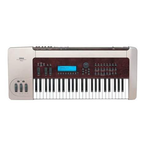
Yamaha VL Manual

Yamaha

Yamaha VL Manual

Yamaha EF2800i - Inverter Generator User manual

Yamaha

Yamaha EF2800i - Inverter Generator User manual

Yamaha EF4000DE - Premium Generator User manual

Yamaha

Yamaha EF4000DE - Premium Generator User manual

Yamaha EF12000DE - Premium Generator User manual

Yamaha

Yamaha EF12000DE - Premium Generator User manual

Yamaha EF7200DE, EF7200D User manual

Yamaha

Yamaha EF7200DE, EF7200D User manual

Yamaha EF4500iSE - Inverter Generator User manual

Yamaha

Yamaha EF4500iSE - Inverter Generator User manual

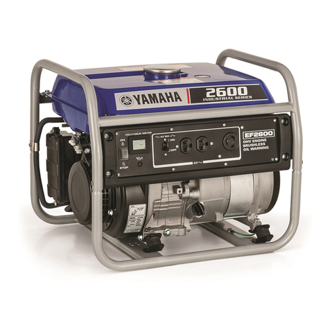
Yamaha EF2600J - Generator - 2600 Maximum AC Output User manual

Yamaha

Yamaha EF2600J - Generator - 2600 Maximum AC Output User manual

Yamaha YVD10 User manual

Yamaha

Yamaha YVD10 User manual

Yamaha EF1000iS User manual

Yamaha

Yamaha EF1000iS User manual

Yamaha EF2000iSv2 User manual

Yamaha

Yamaha EF2000iSv2 User manual

Yamaha EF2200iS User manual

Yamaha

Yamaha EF2200iS User manual

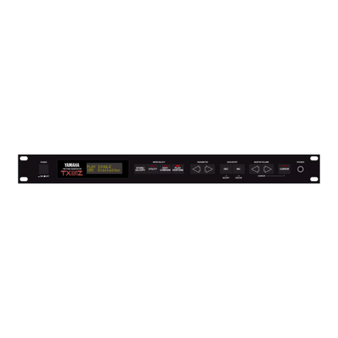
Yamaha TX-81Z User manual

Yamaha

Yamaha TX-81Z User manual

Yamaha EDL20000TE User manual

Yamaha

Yamaha EDL20000TE User manual

Yamaha EF1000iS User manual

Yamaha

Yamaha EF1000iS User manual

Yamaha EF6300iSDE - 5500 Watt Inverter Generator User manual

Yamaha

Yamaha EF6300iSDE - 5500 Watt Inverter Generator User manual

Yamaha EF1000iS User manual

Yamaha

Yamaha EF1000iS User manual

Yamaha EF2000iS - Inverter Generator User manual

Yamaha

Yamaha EF2000iS - Inverter Generator User manual

Yamaha FB-01 User manual

Yamaha

Yamaha FB-01 User manual

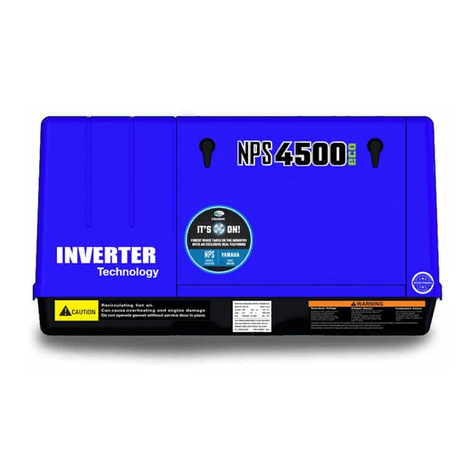
Yamaha NPS 4500 User manual

Yamaha

Yamaha NPS 4500 User manual

Yamaha EF2400iS - Inverter Generator User manual

Yamaha

Yamaha EF2400iS - Inverter Generator User manual

Yamaha EF1000FW User manual

Yamaha

Yamaha EF1000FW User manual

Popular Inverter manuals by other brands

Astrel Group Power Reducer Installation and instruction manual

Astrel Group

Astrel Group Power Reducer Installation and instruction manual

Mitsubishi Electric FR-A7AZ instruction manual

Mitsubishi Electric

Mitsubishi Electric FR-A7AZ instruction manual

MYERS LVU-2 instruction manual

MYERS

MYERS LVU-2 instruction manual

Tektronix CFG250 Operator's manual

Tektronix

Tektronix CFG250 Operator's manual

Wagan AC Inverter user manual

Wagan

Wagan AC Inverter user manual

Srne HES4855S100-H user manual

Srne

Srne HES4855S100-H user manual

Danfoss Type 12 BD150 105N0912 instructions

Danfoss

Danfoss Type 12 BD150 105N0912 instructions

SolaX Power X3-Retro Fit Series user manual

SolaX Power

SolaX Power X3-Retro Fit Series user manual

Cobra CPI 800 operating instructions

Cobra

Cobra CPI 800 operating instructions

Dometic TEC60 operating manual

Dometic

Dometic TEC60 operating manual

Ramsey Electronics SG560 user guide

Ramsey Electronics

Ramsey Electronics SG560 user guide

Baldor IDLC300-3D installation manual

Baldor

Baldor IDLC300-3D installation manual

Generac Power Systems 9592-3 owner's manual

Generac Power Systems

Generac Power Systems 9592-3 owner's manual

Toshiba Q7 Flow Installation and operation manual

Toshiba

Toshiba Q7 Flow Installation and operation manual

Mastervolt Whisper 6 user manual

Mastervolt

Mastervolt Whisper 6 user manual

LSIS LSLV-S100 Series manual

LSIS

LSIS LSLV-S100 Series manual

Shindaiwa DGW300MS/UK Operator's manual

Shindaiwa

Shindaiwa DGW300MS/UK Operator's manual

Hoymiles HMS-700-2T Quick installation guide

Hoymiles

Hoymiles HMS-700-2T Quick installation guide

manuals.online logo
manuals.online logoBrands
  • About & Mission
  • Contact us
  • Privacy Policy
  • Terms and Conditions

Copyright 2025 Manuals.Online. All Rights Reserved.