2 • vacon
CONTENTS
Document code: DPD00426A
Version release date: 25.8.2011
1. SAFETY.......................................................................................................................3
1.1 Danger and warning symbols used in this manual ........................................................ 3
1.2 Symbols and warning marks used in the product .......................................................... 3
1.3 Safety rules ..................................................................................................................... 3
1.4 Earthing and earth fault protection ................................................................................ 4
2. TECHNICAL SPECIFICATIONS....................................................................................6
2.1 Inverter ratings ............................................................................................................... 6
2.2 Technical data ................................................................................................................. 6
3. RECEIPT OF DELIVERY...............................................................................................7
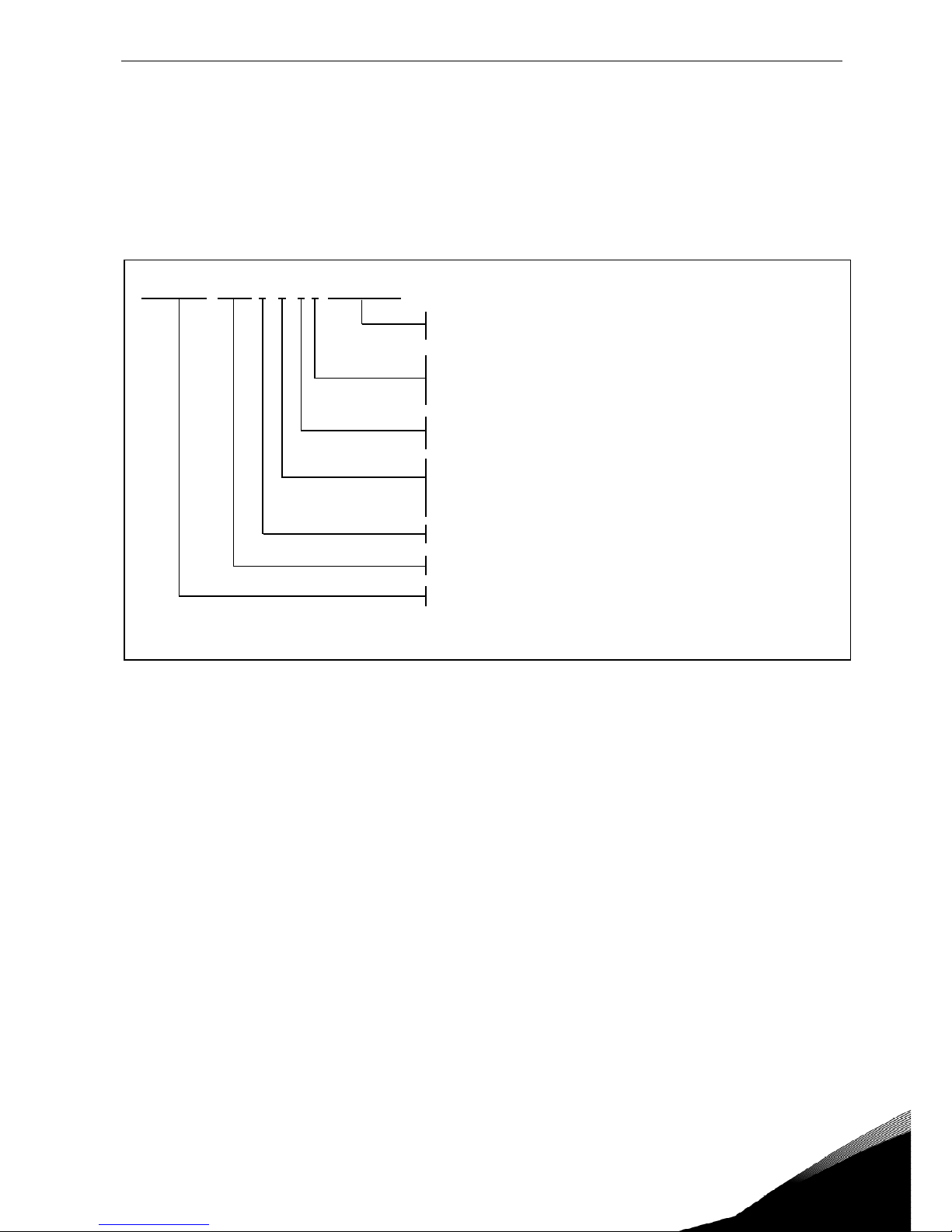
3.1 Type designation code..................................................................................................... 7
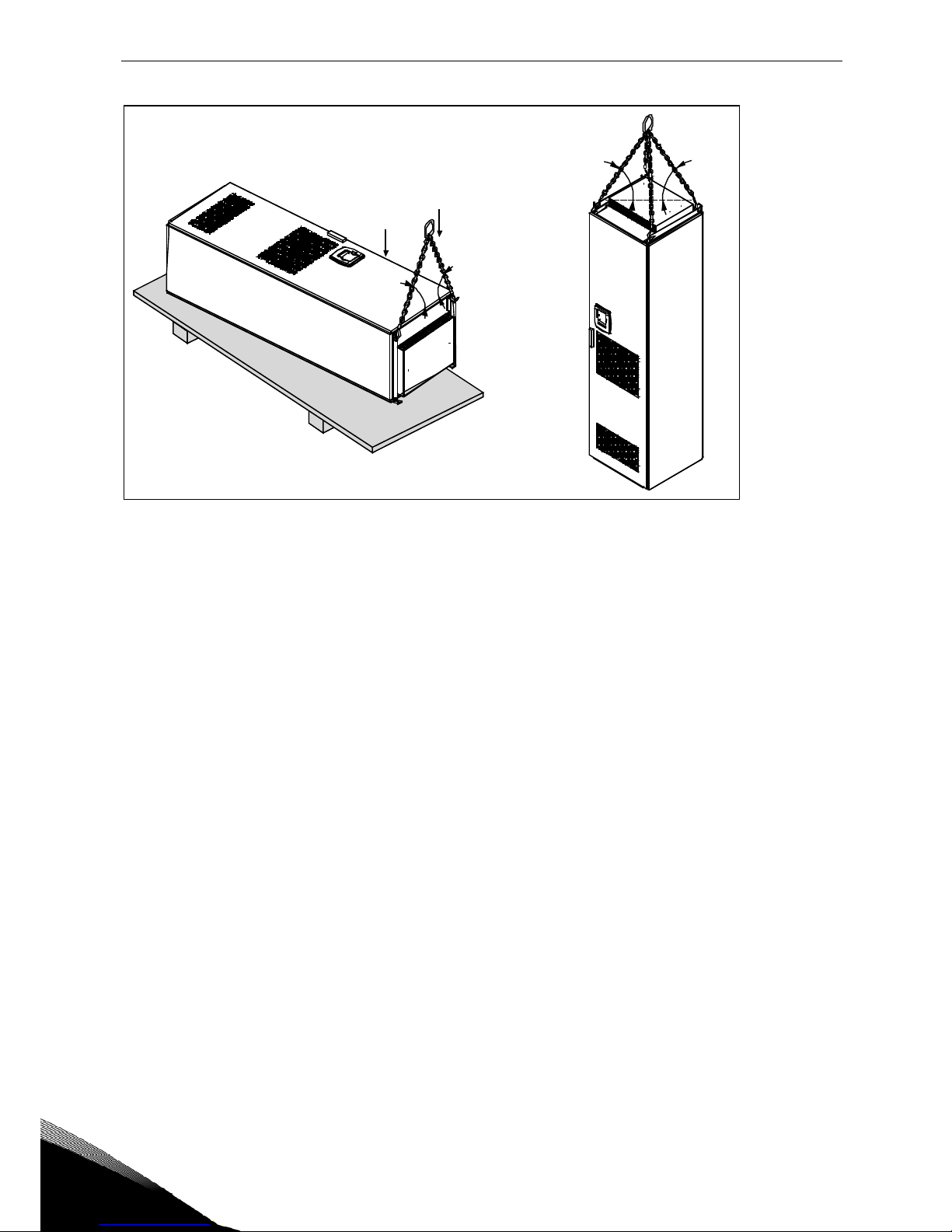
3.2 Lifting the unit out of the transport packaging............................................................... 7
3.3 Storage............................................................................................................................ 8
3.4 Maintenance.................................................................................................................... 9
3.5 Warranty.......................................................................................................................... 9
4. INSTALLATION .........................................................................................................10
4.1 Free space around the cabinet ..................................................................................... 12
4.2 Fixing the unit................................................................................................................ 13
5. ELECTRICAL CONNECTION......................................................................................15
5.1 Electrical diagrams....................................................................................................... 15
5.2 Cabling .......................................................................................................................... 17
5.3 Control connections ...................................................................................................... 22
5.4 Option board OPTC2 (RS-485)....................................................................................... 29
5.5 Option board OPTD7 (Line voltage measurement board)............................................. 30
5.6 Fuse selection ............................................................................................................... 32
6. START UP.................................................................................................................33
6.1 Inverter control keypad................................................................................................. 34
7. MAINTENANCE AND TROUBLESHOOTING...............................................................39
7.1 Maintenance.................................................................................................................. 39
7.2 Troubleshooting ............................................................................................................ 40