Contents
Alert Notifications ...................1
Alert Notifications ................................. 1
Maintenance Notifications .................... 2
General information................3
List of abbreviations ............................. 3
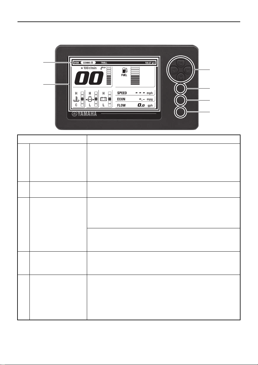
Meter unit.................................4
Initial Setting ...........................6
Configuring the number of outboard
motors ............................................... 6
Configuring the fuel tank sensors......... 7
Calibrating the fuel tank sensors .......... 7
Adjusting the trim level to zero ........... 10
Main screen ...........................11
Switching the screens ........................ 11
COMBO.............................................. 12
ENGINE.............................................. 13
BOAT.................................................. 13
TROLL................................................ 13
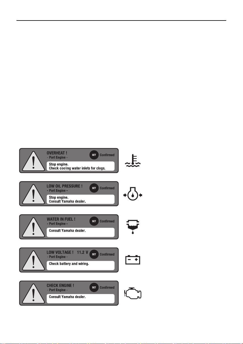
Alert display area................................ 14
Overheat alert ....................................... 14
Low oil pressure alert ............................ 14
Water in fuel alert .................................. 15
Low battery voltage alert ....................... 15
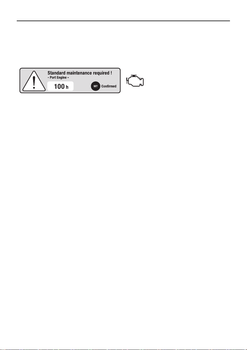
Check engine alert/maintenance
alert ................................................... 15
Y-COP display area............................ 16
Basic display area .............................. 16
Tachometer ........................................... 16
Trim meter............................................. 16
Fuel gauge ............................................ 16
Specific selection area ....................... 17
Adjusting the trolling speed ................ 17
MENU screen.........................19
Switching the screens......................... 19
Features ............................................. 20
Menu items ......................................... 21
Resetting “Trip” information (Trip) ......... 21
Managing the maintenance schedule
(Maintenance) ................................... 21
Changing backlight settings
(Brightness)....................................... 22
Customizing the screen (Favorites) ...... 23
Setting the background color (Color) .... 31
Adjusting the clock (Clock).................... 31
Setting the displayed units (Units)......... 32
Setting the tanks (Tank Set).................. 33
Initializing the meter (Reset) ................. 34
Adjusting the trim level to zero
(Trim level) ........................................ 34
Calibration of fuel consumption
(Fuel Flow) ........................................ 35
Trouble Codes....................................... 35
Appendix ...............................37
Requirements for installation .............. 37
Proper care of the instrument ............. 37
Template (actual size) ........................ 38
00_6YC_owners_En.book Page 0 Sunday, March 1, 2015 3:36 PM