Yamaha EMX 660 User manual

EEEngine
HIGH
MID
LOW
MONI
EFFECT
LEVEL
HIGH
MID
LOW
MONI
EFFECT
LEVEL
HIGH
MID
LOW
MONI
EFFECT
LEVEL
HIGH
MID
LOW
MONI
EFFECT
LEVEL
2
2
3
3
4
4
5
5
6
6
INPUT OUTPUT
MONITOR
MAIN
AUX IN
REC
OUT
TAPE
IN
EFFECT OUT
FOOT SW
12
11
22
12
LINEHi-Z INST
MIC MICLo-Z
Hi-Z
Lo-Z
Hi-Z
Lo-Z
Hi-Z
Lo-Z
SEE REAR PANEL CAUTION
MONITOR
MASTER
EFFECT RTN
+6
+3
0
–5
–10
+12
•
6
•
0
•
6
•
–12
+12
•
6
•
0
•
6
•
–12
125 250 500 1k 2k 4k 8k
010
TAPE IN
010 010
MAIN
MASTER
TAPE IN
AUX INEFFECT RTN
+6
+3
0
–5
–10
+12
•
6
•
0
•
6
•
–12
+12
•
6
•
0
•
6
•
–12
125 250 500 1k 2k 4k 8k
010010010 010
HIGH
MID
LOW
MONI
EFFECT
LEVEL
1
1
–15 +15
–15 +15
–15 +15
010
010
010
–15 +15
–15 +15
–15 +15
010
010
010
–15 +15
–15 +15
–15 +15
010
010
010
–15 +15
–15 +15
–15 +15
010
010
010
–15 +15
–15 +15
–15 +15
010
010
010
–15 +15
–15 +15
–15 +15
010
010
010
DIGITAL
EFFECT
ON
VO. ECHO 1
VO. ECHO 2
VO. REV. 1
VO. REV. 2
HALL. 1
HALL. 2
ROOM
PLATE
HIGH
MID
LOW
MONI
EFFECT
LEVEL
PAD PAD PAD PAD
POWER AMP
12
LIMITER
MAIN
BRIDGE
MAIN
MONITOR
MAIN
MAIN
2
A
MPs
300W 300W
POWER
ON
OFF
PHANTOM
EEEngine
POWERED MIXER
Owner’s Manual
E

FCC INFORMATION (U.S.A.)
1. IMPORTANT NOTICE: DO NOT MODIFY THIS UNIT! This product, when installed as indicated in the instructions contained in this manual, meets FCC
requirements. Modifications not expressly approved by Yamaha may void your authority, granted by the FCC, to use the product.
2. IMPORTANT: When connecting this product to accessories and/or another product use only high quality shielded cables. Cable/s supplied with this product MUST
be used. Follow all installation instructions. Failure to follow instructions could void your FCC authorization to use this product in the USA.
3. NOTE: This product has been tested and found to comply with the requirements listed in FCC Regulations, Part 15 for Class “B” digital devices. Compliance with
these requirements provides a reasonable level of assurance that your use of this product in a residential environment will not result in harmful interference with
other electronic devices. This equipment generates/uses radio frequencies and, if not installed and used according to the instructions found in the users manual, may
cause interference harmful to the operation of other electronic devices. Compliance with FCC regulations does not guarantee that interference will not occur in all
installations. If this product is found to be the source of interference, which can be determined by turning the unit “OFF” and “ON”, please try to eliminate the
problem by using one of the following measures: Relocate either this product or the device that is being affected by the interference. Utilize power outlets that are on
different branch (circuit breaker or fuse) circuits or install AC line filter/s. In the case of radio or TV interference, relocate/reorient the antenna. If the antenna lead-in
is 300 ohm ribbon lead, change the lead-in to coaxial type cable. If these corrective measures do not produce satisfactory results, please contact the local retailer
authorized to distribute this type of product. If you can not locate the appropriate retailer, please contact Yamaha Corporation of America, Electronic Service
Division, 6600 Orangethorpe Ave, Buena Park, CA 90620
The above statements apply ONLY to those products distributed by Yamaha Corporation of America or its subsidiaries.
WARNING: THIS APPARATUS MUST BE EARTHED
IMPORTANT
THE WIRES IN THIS MAINS LEAD ARE COLOURED IN
ACCORDANCE WITH THE FOLLOWING CODE:
GREEN-AND-YELLOW : EARTH
BLUE : NEUTRAL
BROWN : LIVE
As the colours of the wires in the mains lead of this apparatus may
not correspond with the coloured markings identifying the terminals in
your plug, proceed as follows:
The wire which is coloured GREEN and YELLOW must be
connected to the terminal in the plug which is marked by the letter E
or by the safety earth symbol or coloured GREEN and YELLOW.
The wire which is coloured BLUE must be connected to the terminal
which is marked with the letter N or coloured BLACK.
The wire which is coloured BROWN must be connected to the
terminal which is marked with the letter L or coloured RED.
* This applies only to products distributed by YAMAHA KEMBLE
MUSIC (U.K.) LTD.

Precautions
1
EMX660—Owner’s Manual
Precautions
• Do not allow water to enter this unit or allow the
unit to become wet. Fire or electrical shock may
result.
• Connect this unit’s power cord only to an AC
outlet of the type stated in this Owner’s Manual
or as marked on the unit. Failure to do so is a fire
and electrical shock hazard.
• Do not scratch, bend, twist, pull, or heat the
power cord. A damaged power cord is a fire and
electrical shock hazard.
• Do not place heavy objects, including this unit,
on top of the power cord. A damaged power cord
is a fire and electrical shock hazard. In particular,
be careful not to place heavy objects on a power
cord covered by a carpet.
• If you notice any abnormality, such as smoke,
odor, or noise, or if a foreign object or liquid gets
inside the unit, turn it off immediately. Remove
the power cord from the AC outlet. Consult your
dealer for repair. Using the unit in this condition
is a fire and electrical shock hazard.
• Should this unit be dropped or the cabinet be
damaged, turn the power switch off, remove the
power plug from the AC outlet, and contact your
dealer. If you continue using the unit without
heeding this instruction, fire or electrical shock
may result.
• If the power cord is damaged (i.e., cut or a bare
wire is exposed), ask your dealer for a replace-
ment. Using the unit with a damaged power cord
is a fire and electrical shock hazard.
• Do not remove the unit’s cover. You could receive
an electrical shock. If you think internal inspec-
tion, maintenance, or repair is necessary, contact
your dealer.
• Do not modify the unit. Doing so is a fire and
electrical shock hazard.
• When rack-mounting the unit, allow enough free
space around the unit for normal ventilation.
This should be: 30 cm at the sides, 30 cm behind,
and 40 cm above.
For normal ventilation during use, remove the
rear of the rack or open a ventilation hole.
If the airflow is not adequate, the unit will heat
up inside and may cause a fire.
• This unit has ventilation holes at the rear to pre-
vent the internal temperature rising too high. Do
not block them. Blocked ventilation holes are a
fire hazard.
• Clean the contacts of the phone plug before con-
necting it to the SPEAKERS jack of this unit.
Dirty contacts may generate heat.
• Use only speaker cables when connecting speak-
ers to amplifier outputs. Using other types of
cables is a fire hazard.
Hold the power cord plug when disconnecting it
from an AC outlet. Never pull the cord. A dam-
aged power cord is a potential fire and electrical
shock hazard.
• Do not touch the power plug with wet hands.
Doing so is a potential electrical shock hazard.
• The digital circuits of this unit may induce a
slight noise into nearby radios and TVs. If noise
occurs, relocate the affected equipment.
• Using a mobile telephone near this unit may
induce noise. If noise occurs, use the telephone
away from the unit.
• XLR-type connectors are wired as follows: pin 1:
ground, pin 2: hot (+), and pin 3: cold (-).
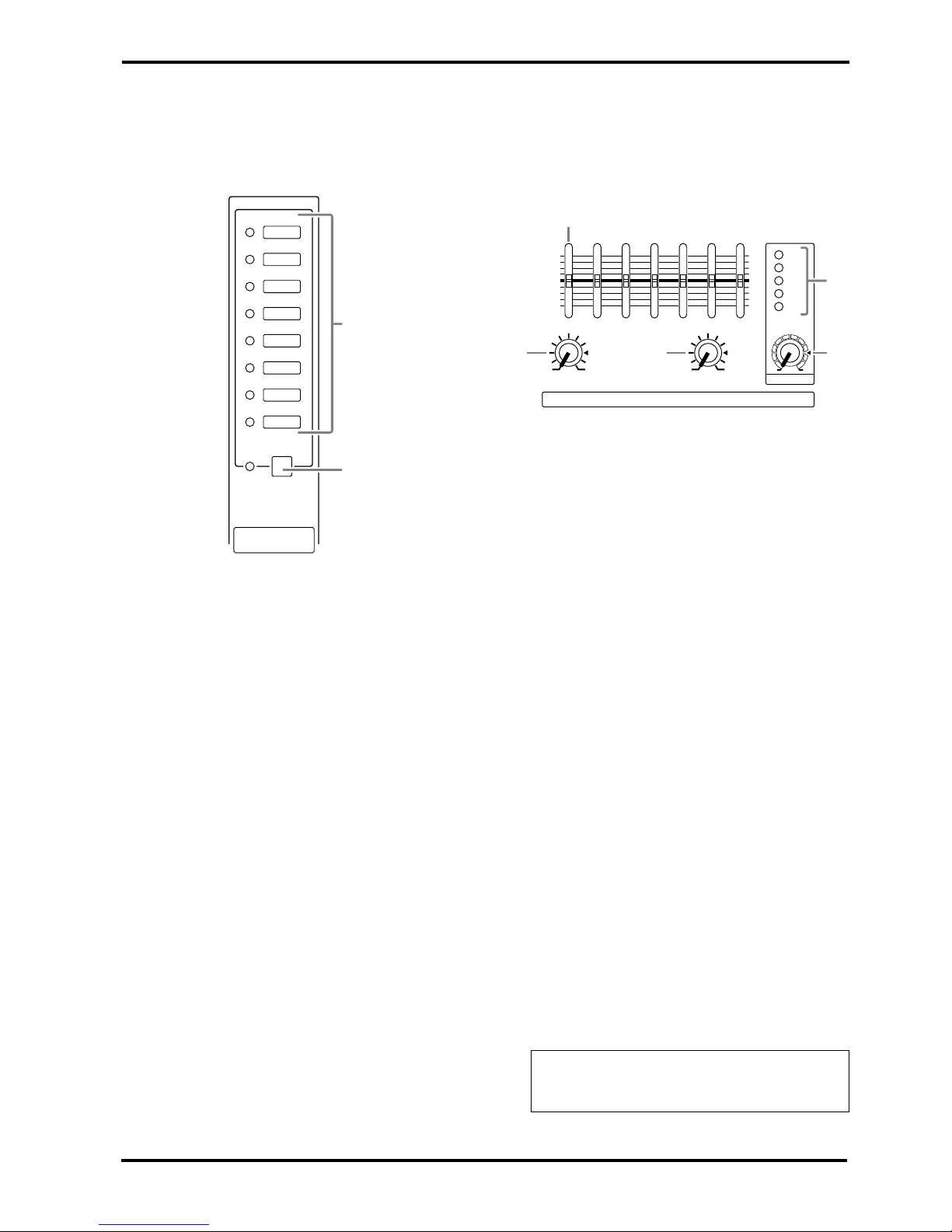
• Do not set all equalizer controls and faders to
maximum. Doing so may cause oscillation
depending on the condition of the connected
unit and speakers, and may damage the speakers.
• The performance of components with moving
contacts, such switches, rotary controls, faders,
and connectors, deteriorates over time. The rate
of deterioration depends on the operating envi-
ronment and is unavoidable. Consult your dealer
about replacing defective components.

2
EMX660—Owner’s Manual

Introduction
3
EMX660—Owner’s Manual
Introduction
Thank you for purchasing the Yamaha EMX660 Powered Mixer. The EMX660 has the following features.
In order to take full advantage of the EMX660 and enjoy long and trouble-free performance, please read this
owner’s manual carefully, and keep it in a safe place for future reference.
Features
• The EMX660 provides six input channels com-
patible with mic/line signals, including high-
impedance input suitable for an electric-acoustic
guitar. The EMX660 has ample power, with a
maximum output of 300 W+300 W (600 W with
bridge connection), and is suitable for a wide
range of applications from installed systems to
small-scale PA systems.
• A two-channel power amp is built-in. The input
signals for the two channels can be selected as
MAIN+MAIN, MAIN+MONITOR, or MAIN
(bridge connection).
• Independent 7-band graphic EQ is provided for
both the MONITOR section and the MAIN sec-
tion. This allows the volume and frequency
response to be adjusted separately for the main
speakers and monitor speakers.
• The power amp section has a limiter circuit to
prevent sound distortion and protect the speak-
ers.
• A digital effect with eight selectable effect types is
built-in.
A variety of effects can be applied to add rever-
beration or ambiance to vocals or instrumental
sounds.
Contents
Front and rear panel ...................................................4
Control panel ........................................................4
Input/output panel .................................................8
Rear panel ..........................................................10
Installation/Connection .............................................11
Installation ..........................................................11
Connection .........................................................11
Basic Operation ........................................................13
Connecting microphones and instruments .........13
Monitoring ...........................................................13
Using the digital effect ........................................13
Example setups ........................................................14
As a conference PA system/installed
sound system .....................................................14
As a band PA ......................................................15
Troubleshooting .......................................................17
Specifications ...........................................................18
General specifications ........................................18
Input specifications..............................................19
Output specifications ..........................................19
Dimensions..........................................................20
Block and Level diagram.....................................21

4
Front and rear panel
EMX660—Owner’s Manual
Front and rear panel
Control panel
■
Channel section
In this section, you can adjust equalization (fre-
quency response), volume level, effect and moni-
tor output levels for the input signal of each
channel.
1
Equalizer controls (HIGH, MID, LOW)
This is a 3-band equalizer that adjusts the high
frequency range, mid frequency range, and low
frequency range of each channel. Response is flat
when the knobs are in the
▼
position. Rotating it
toward the right will boost the corresponding fre-
quency band, and rotating it toward the left will
cut it.
The base frequency (or center frequency), range
of boost or cut, and equalizer type of each band
are as follows.
HIGH: 12 kHz ±15 dB shelving type
MID: 2.5 kHz ±15 dB peaking type
LOW: 80 Hz ±15 dB shelving type
2
Monitor controls (MONI)
For each channel, this controls the amount of sig-
nal that is sent to the MONITOR bus.
The signal of the MONITOR bus is sent to the
speakers connected to the POWER AMP 2 A/B
jacks (only if the power amp select switch is in the
MAIN-MONITOR position) and to the MONI-
TOR jacks (input/output panel
6
).
3
Effect control (EFFECT)
For each channel, this controls the amount of sig-
nal that is sent to the EFFECT bus.
The signal of the EFFECT bus is sent to the built-
in effect and to the EFFECT OUT jacks (input/
output panel
3
).
4
Level control (LEVEL)
This adjusts the output level for each channel.
5
Pad switch (PAD) (Channel 1–4 only)
This switch attenuates the input signal by 30 dB.
When connecting a line level device to channels
1–4, or if the mic input is distorted, turn this
switch on (the pressed-in position).
PAD
HIGH
MID
LOW
MONI
EFFECT
LEVEL
1
1
–15 +15
–15 +15
–15 +15
010
010
010
1
2
3
4
5
Note:
The signal is sent to the MONITOR bus
from a location before the level control (
4
) of
each channel. This means that it will not be af-
fected by the setting of the LEVEL control.
Note:
The signal is sent to the EFFECT bus
from a location after the level control (
4
) of
each channel. This means that the amount of
signal that is sent to the EFFECT bus will be af-
fected not only by the setting of the effect con-
trol, but also by the setting of the level control.

Control panel
5
EMX660—Owner’s Manual
■
DIGITAL EFFECT section
This section allows you to turn the built-in digital
effect on/off and to select the effect type.
6
Effect select switch and indicator
Select the effect type for the built-in digital effect.
The indicator of the selected effect type lights up.
7
DIGITAL EFFECT ON switch and indicator
When this switch is on (pressed), the indicator
lights up and the built-in digital effect can be
used. In that case, the signal processed by the dig-
ital effect will be sent to the MAIN/MONITOR
bus. The mix level of the effect sound is adjusted
by the EFFECT RTN control of the MAIN and
MONITOR sections.
■
MONITOR section
This section allows you to adjust the tone and
volume of the MONITOR bus, and specify the
mix level of the built-in effect and the external
input signals.
8
Graphic equalizer
This is a 7-band graphic equalizer that allows you
to adjust the frequency response of the MONI-
TOR bus signal, providing a maximum of ±12 dB
of cut/boost for each frequency band.You can use
these sliders to reduce the level of frequency
bands at which feedback easily occurs. Frequency
response is flat when a slider is in the center posi-
tion. Moving a slider in the positive direction will
boost, and in the negative direction will cut.
This graphic equalizer affects both the MONI-
TOR bus signal that is output to the speakers and
the line level signal which is output from the
MONITOR jack (input/output panel
6
).
9
EFFECT RTN control
This controls the level of the effect sound which
is returned from the built-in digital effect to the
MONITOR bus.
0
TAPE IN control
This controls the level of the signal routed from
the TAPE IN jack to the MONITOR bus.
A
MASTER control
This adjusts the final level of the MONITOR bus.
It affects both the MONITOR bus signal which is
output to the speakers and the line level signal
which is output to the MONITOR jack (input/
output panel
6
).
B
Peak level indicator
This indicator allows you to monitor the level of
the signal which is output from the MONITOR
jack (input/output panel
6
).
DIGITAL
EFFECT
ON
VO. ECHO 1
VO. ECHO 2
VO. REV. 1
VO. REV. 2
HALL. 1
HALL. 2
ROOM
PLATE
6
7
Note:
To avoid distortion, adjust the MASTER
control (
A
) so that the 0 indicator lights occa-
sionally.
MONITOR MASTER
EFFECT RTN
+6
+3
0
–5
–10
+12
•
6
•
0
•
6
•
–12
+12
•
6
•
0
•
6
•
–12
125 250 500 1k 2k 4k 8k
8
B
9A
010 TAPE IN
0
010 010

6
Front and rear panel
EMX660—Owner’s Manual
■
MAIN section
This section allows you to adjust the tone and
volume of the MAIN bus, the mix level of the
built-in effect, and the mix level of the external
input.
C
Graphic equalizer
This is a 7-band graphic equalizer that allows you
to adjust the frequency response of the MAIN
bus signal, providing a maximum of ±12 dB of
cut/boost for each frequency band.
This graphic equalizer affects both the MAIN bus
signal that is output to the speakers and the line
level signal which is output from the MAIN jack
(input/output panel
6
).
D
EFFECT RTN control
This adjusts the level of the effect signal which is
returned from the built-in digital effect to the
MAIN bus.
E
AUX IN control
This adjusts the amount of signal that is sent
from the AUX IN jack to the MAIN bus.
F
TAPE IN
This adjusts the amount of signal that is sent
from the TAPE IN jacks to the MAIN bus.
G
MASTER control
This adjusts the final level of the MAIN bus. It
affects both the MAIN bus signal which is output
from the speakers, and the line level signal which
is output from the MAIN jack (input/output
panel
6
).
H
Peak level indicator
This indicator allows you to monitor the level of
the signal which is output from the MAIN jack
(input/output panel
6
).
■
POWER AMP section
This section allows you to select the signals that
will be output from the built-in two-channel
power amplifier, and to select the BRIDGE mode.
I
LIMITER indicator
This indicator lights up when the level of the sig-
nal output from the power amp section reaches
the maximum and the limiter is activated. Adjust
appropriate control so that the indicator lights up
for only a short while when the signal reaches the
maximum level.
J
Power amp select switch
Select one of the following three settings to spec-
ify the signals that will be output from power
amp 1/2.
• MAIN BRIDGE
With this setting, the MAIN bus signal will be
output from the BRIDGE jack. The two power
amp channels (A and B) will be bridge con-
nected. Only the MASTER control
G
in the
MAIN section becomes effective.
•
MAIN-MAIN
With this setting, the MAIN bus signal will be
output from the POWER AMP 1 A/B jacks and
from the POWER AMP 2 A/B jacks. Only the
MASTER control
G
in the MAIN section
becomes effective.
• MAIN-MONITOR
With this setting, the MAIN bus signal will be
output from the POWER AMP 1 A/B jacks and
the MONITOR bus signal is output from the
POWER AMP 2 A/B jacks. Only the MASTER
controls in the MAIN and MONITOR sections
G
,
A
are both effective.
Note:
To avoid distortion, adjust the MASTER
control (
G
) so that the 0 indicator lights occa-
sionally.
MAIN
MASTER
TAPE IN
AUX INEFFECT RTN
+6
+3
0
–5
–10
+12
•
6
•
0
•
6
•
–12
+12
•
6
•
0
•
6
•
–12
125 250 500 1k 2k 4k 8k
CH
G
DEF
010010010 010
Note:
The indicator lights up or flashes for a
longer duration if the power amp section is sig-
nificantly overloaded, which could result in
malfunction. Avoid such a situation.
POWER AMP
12
LIMITER
MAIN
BRIDGE
MAIN
MONITOR
MAIN
MAIN
2A
MPs
300W 300W
J
I

Control panel
7
EMX660—Owner’s Manual
■
POWER indicator & PHANTOM
switch
K
POWER indicator
This indicator will light when the power of the
EMX660 is turned on.
L
PHANTOM switch
This switch turns the phantom power supply on/
off for the Lo-Z input jacks of channels 1–4 and
MIC input jacks of channels 5–6.
Turn this switch off if you do not use it.
K
L
POWER
ON
OFF PHANTOM

8
Front and rear panel
EMX660—Owner’s Manual
Input/output panel
1
Hi-Z, Lo-Z input jacks
These are the input jacks for channels 1–4. By
using the PAD switches (control panel
5
) you
can connect any of the jacks to a wide range of
sources from mics to line level devices (synthesiz-
ers or rhythm boxes etc.). The Lo-Z jacks can
provide +15 V phantom power, allowing you to
use condenser microphones.
Both Hi-Z and Lo-Z are balanced, and are com-
patible with microphones of output impedance
50–600
Ω
or line level devices of 600
Ω
. The nom-
inal input level is –40 dB – –10 dB for the Hi-Z
jacks, and –50 dB – –20 dB for the Lo-Z jacks.
Pin connections for the Hi-Z and Lo-Z jacks are
as follows.
2
MIC, LINE, INST input jacks
These are the input jacks for channels 5–6.
Microphones can be connected to the MIC jacks,
and stereo line level devices (such as synthesizers
or rhythm boxes) can be connected to the LINE
jacks.
The MIC jacks are balanced, and are compatible
with microphones of output impedance 50–
600
Ω
.
The LINE
1
&
2
jacks are unbalanced, and are
compatible with line level devices of 600
Ω
output
impedance. These two input jacks can be used
simultaneously.
Nominal input level is –50 dB for the MIC jacks
and –10 dB for the LINE jacks.
INST
1& 2jacks are unbalanced, can be used
simultaneously, and their high input impedance
makes them ideal for use with instruments such
as electric-acoustic guitar and electric bass. They
can also be used with line-level sources, such as
synthesizers and drum machines. Nominal input
level is –30 dB.
3Effect output jack (EFFECT OUT)
The input of an external effect such as a delay or
echo can be connected to this jack.
The signal adjusted by the EFFECT control of
each channel will be sent to the EFFECT bus, and
output from this jack.
The nominal output level and impedance are
+4 dB/10 kΩ.
4Foot switch jack (FOOT SW)
A separately sold Yamaha FC5 foot switch can be
connected to this jack. If a foot switch is con-
nected to this jack, you can use your foot to
switch the built-in digital effect on/off.
INPUT OUTPUT
MONITOR
MAIN
AUX IN
REC
OUT
TAPE
IN
EFFECT OUT
FOOT SW
12
11
22
12
LINEHi-Z INST
MIC MICLo-Z
Hi-Z
Lo-Z
Hi-Z
Lo-Z
Hi-Z
Lo-Z
SEE REAR PANEL CAUTION
21 5 6
43
EEEngine
Lo-Z jacks
(XLR type) Hi-Z jacks
(TRS phone jacks)
Pin 1: ground Sleeve: ground
Pin 2: hot (+) Tip: hot (+)
Pin 3: cold (–) Ring: cold (–)
Note: It is not possible to simultaneously use
both the Hi-Z and Lo-Z inputs of a given chan-
nel. For each channel, use only one of the inputs
as appropriate for the input source.
Phantom power is switched on/off in simulta-
neously for the Lo-Z jacks of channels 1–4 and
the MIC jacks of channels 5–6. For this reason,
any devices other than condenser microphones
must be connected to the Hi-Z or LINE jacks if
the PHANTOM switch (control panel L) is on.
GND
RST
+-
GND
+-
Note: It is possible to simultaneously use both
the MIC and LINE inputs for channel 5, and the
MIC and INST inputs for channel 6.

Input/output panel 9
EMX660—Owner’s Manual
5External input jacks (AUX IN/TAPE IN)
These are input jacks that allow the signal from
an external device to be added to the MAIN out-
put. Monaural output devices such as external
effects can be connected to the AUX IN jack, and
stereo output devices such as cassette recorder or
CD players can be connected to the TAPE IN
jacks.
The nominal input level and impedance are –10 dB/
600Ωfor the AUX IN jack, and –10 dBV/600Ωfor
the TAPE IN jacks.
6External output jacks (REC OUT/MONI-
TOR/MAIN)
These are output jacks which send line level sig-
nals from the EMX660 to external devices.
A stereo recording device such as a cassette deck,
DAT or MD recorder can be connected to the
REC OUT jacks, and a playback device such a
power amp can be connected to the MONITOR
and MAIN jacks. The signals sent from each jack
are as follows.
•REC OUT jacks: The MAIN bus signal before it
has passed through the MASTER control and
graphic equalizer
•MONITOR jack: The MONITOR bus signal
which has passed through the Monitor MASTER
control and graphic equalizer
•MAIN jack: The MAIN bus signal which has
passed through the Main MASTER control and
graphic equalizer
The nominal output level and impedance are
–10 dBV/10 kΩfor the REC OUT jacks, and
+4 dB/10 kΩfor the MONITOR/MAIN jacks.

10 Front and rear panel
EMX660—Owner’s Manual
Rear panel
1Speaker output jacks (POWER AMP 1 A/B,
POWER AMP 2 A/B, BRIDGE)
Speakers can be connected to these jacks. The
EMX660 contains a two-channel power amp, and
there are three ways in which the speakers can be
connected to the EMX660.
At this time, use the power amp select switch J
on the control panel to select a signal sent to the
correct jacks.
■When the power amp select switch is set to
MAIN-MONITOR or MAIN-MAIN:
• Two-channel connection
Two 4–8Ωspeakers can be connected to the A
jack or B jack of the POWER AMP 1/2 (maxi-
mum output 300W+300W).
• Two-channel parallel connection
Two 8–16Ωspeakers can be connected to the
POWER AMP 1 A/B jacks and two more to the
POWER AMP 2 A/B jacks, for a total of four
speakers (maximum output 300 W+300 W).
■When the power amp select switch is set to
MAIN-BRIDGE (Bridge connection)
• One 8–16Ωspeaker can be connected to the
BRIDGE jack (maximum output 600 W).
2Power switch
This switch turns the power of the EMX660 on/
off.
SPEAKERS
POWER BABA
POWER AMP 1
BRIDGE
POWER AMP 2
ON / OFF
12
Caution:
When using a bridge connection, do not con-
nect anything to the POWER AMP 1 and POW-
ER AMP 2 jacks. Likewise, when using the
POWER AMP 1 and/or POWER AMP 2 jacks,
do not connect anything to the BRIDGE jack.
Note: Before turning the EMX660 on/off, turn
down the MASTER controls of the MONITOR
and MAIN section.

Installation/Connection 11
EMX660—Owner’s Manual
Installation/Connection
Installation
The EMX660 uses a forced cooling system with intake on the bottom of the rear panel and exhaust on the top
of the rear panel to avoid blocking the heated air flow.
Connection
When connecting various devices, be sure to use cables and plugs of the appropriate standard.
■Speaker connection
There are three ways in which speakers can be connected to the EMX660.
1Two-channel connection — A single speaker each can be connected to either the A or the B jack of POWER
AMP 1 and of POWER AMP 2.
2Two-channel parallel connection — Two speakers can be connected in parallel to both the A and B jacks of
POWER AMP 1 and of POWER AMP 2.
3Bridge connection — A single speaker can be connected to the BRIDGE jack.
For each of these, the required speaker impedance will differ. Refer to the following diagram, and make sure
that the speaker impedance is not less than the specified value.
NO NO
Front
Front
30cm
or less
Exhaust
Intake
8Ω~16Ω
4Ω~8Ω4Ω~8Ω8Ω~16Ω8Ω~16Ω8Ω~16Ω8Ω~16Ω
SPEAKERS BABA
POWER AMP 1
BRIDGE
POWER AMP 2
SPEAKERS BABA
POWER AMP 1
BRIDGE
POWER AMP 2
SPEAKERS BABA
POWER AMP 1
BRIDGE
POWER AMP 2
No
connection
No
connection
No
connection
No
connection
MAIN
BRIDGE
MAIN
MONITOR
MAIN
MAIN
MAIN
BRIDGE
MAIN
MONITOR
MAIN
MAIN
MAIN
BRIDGE
MAIN
MONITOR
MAIN
MAIN
or
Main
Speaker
Main Speaker
Main
Speakers
Main/Monitor
Speaker Main/Monitor
Speakers
Bridge connection
Two-channel connection Two-channel parallel connection

12 Installation/Connection
EMX660—Owner’s Manual
■Example connections
INPUT OUTPUT
MONITOR
MAIN
AUX IN
REC
OUT
TAPE
IN
EFFECT OUT
FOOT SW
12
11
22
12
LINEHi-Z INST
MIC MICLo-Z
Hi-Z
Lo-Z
Hi-Z
Lo-Z
Hi-Z
Lo-Z
SEE REAR PANEL CAUTION
EEEngine
88
*1
The figure above shows appropriate jacks to
connect each instrument.
*1. Although this example shows an external effects
processor and footswitch, which is used to turn
on and off the built-in digital effects processor,
connected to the EMX660, in practice, only one
effects processor, internal or external, will be
used at a time, so the footswitch is not required
when using external effects.
* The Lo-Z and Hi-Z input of each channel cannot
be used simultaneously.
Electric bass
Microphone
Effects processor
Recorder (Cassette, DAT, MD)
CD player
Synthesizer,
Drum machine,
Guitar processor
Footswitch
(YAMAHA FC5)
Electric-acoustic
guitar Normally, connect speakers to the
jacks on the rear panel. If more
speaker outputs are needed, use the
MAIN (STEREO) jacks for stereo
output and the MONITOR jack for
monaural output.
Monitors Speakers
Main Speakers
Power AMP

Basic Operation 13
EMX660—Owner’s Manual
Basic Operation
This section explains basic operation of the EMX660.
Connecting microphones
and instruments
1Before connecting mics or instruments,
make sure that the power of all equip-
ment (where applicable) is turned off.
Also make sure that the level controls of
each channel of the EMX660 and the
MASTER control of the MAIN section are
turned down.
2Connect cables to your mics and instru-
ments, and insert the other end of the
cable firmly into the appropriate Lo-Z/Hi-
Z jack (channels 1–4) or the MIC jack
(channels 5–6), LINE jack (channels 5),
INST jack (channels 6).
3Turn the power on in the order of periph-
eral devices ➞EMX660.
4Set the MAIN section MASTER control to
the √√
√√ position.
5While speaking into the mic (while play-
ing the instrument), adjust the channel
LEVEL control so that the 0 LED of the
MAIN section peak level meter lights
occasionally.
Repeat this step for each channel.
6If you wish to adjust the tone of each
channel, rotate the equalizer controls as
desired.
7Use the MAIN section graphic equalizer
to adjust the tone.
8Use the MAIN MASTER control to adjust
the overall volume.
Monitoring
By connecting a powered monitor speaker to the
MONITOR OUTPUT, you can create a monitor
mix independent of the MAIN mix, since the
input channel MONI controls are not affected by
the LEVEL controls.
1Set the MONI MASTER control to the √√
√√
position.
2While speaking into a connected mic, or
playing a connected instrument, adjust
the MONI control of the input channel
that you want to monitor.
Repeat this procedure for each channel.
3Use the MONI MASTER control to set the
overall level of the monitor mix.
Using the digital effect
The EMX660 has a built-in digital effect, allow-
ing reverberation or ambiance to be added to
vocals or instrumental sounds.
1Press the DIGITAL EFFECT ON switch of
the DIGITAL EFFECT section.
2Use the effect select switches of the DIGI-
TAL EFFECT section to select the effect
type.
VO.ECHO 1, 2 .....Echo appropriate for vocals.
VO.REV. 1, 2........Reverb appropriate for vocals.
HALL 1, 2 .............Reverb typical of a hall.
ROOM..................Reverb typical of a room.
PLATE .................Plate echo-like reverberation
3Set the MAIN EFFECT RTN control to the
√√
√√ position.
4Raise the EFFECT control of the channels
to which you wish to apply the digital
effect.
5Use the MAIN/MONITOR section EFFECT
RTN control to adjust the level of the
sound processed by the effect.
Note: When connecting a line level device to
channels 1–4, turn on the PAD switch.
You cannot use a channel’s Lo-Z and Hi-Z jacks
at the same time. The MIC and LINE jacks, or
the MIC and INST jacks, however, can be used
at the same time.
Note: When turning the power off, reverse this
sequence.
Note: If the effect sound is distorted even if the
EFFECT RTN turned all the way down, lower
the EFFECT controls of each channel.

14 Example setups
EMX660—Owner’s Manual
Example setups
This section provides some ways in which the EMX660 can be used, and explains connections and operation.
As a conference PA system/installed sound system
Here is an example of using the EMX660 as a conference PA system or as an installed sound system.
Connections
• Connect mics to channel inputs 1–6.
• If you wish to use an external device such as a CD
player or LD player, connect the outputs of the
device to the TAPE IN jacks of the EMX660.
• If you wish to record the audio to a cassette deck,
connect the REC OUT jacks of the EMX660 to
the input jacks of the cassette deck.
• Connect the main speakers to the A/B jacks of the
POWER AMP 1/2, and set the power amp select
switch to "MAIN-MAIN."
Playing back a CD player
1Turn the power on in the order of periph-
eral devices ➞EMX660.
2Adjust the MASTER control of the MAIN
section to the √√
√√ position.
3Start playback on the CD player, and use
the MAIN section TAPE IN control to
adjust the level so that the 0 LED of the
MAIN section peak level meter does not
light.
HIGH
MID
LOW
MONI
EFFECT
LEVEL
HIGH
MID
LOW
MONI
EFFECT
LEVEL
HIGH
MID
LOW
MONI
EFFECT
LEVEL
HIGH
MID
LOW
MONI
EFFECT
LEVEL
2
2
3
3
4
4
5
5
6
6
INPUT OUTPUT
MONITOR
MAIN
AUX IN
REC
OUT
TAPE
IN
EFFECT OUT
FOOT SW
12
11
22
12
LINEHi-Z INST
MIC MICLo-Z
Hi-Z
Lo-Z
Hi-Z
Lo-Z
Hi-Z
Lo-Z
SEE REAR PANEL CAUTION
MONITOR MASTER
EFFECT RTN
+6
+3
0
–5
–10
+12
•
6
•
0
•
6
•
–12
+12
•
6
•
0
•
6
•
–12
125 250 500 1k 2k 4k 8k
010 TAPE IN
010 010
MAIN
MASTER
TAPE IN
AUX INEFFECT RTN
+6
+3
0
–5
–10
+12
•
6
•
0
•
6
•
–12
+12
•
6
•
0
•
6
•
–12
125 250 500 1k 2k 4k 8k
010010010 010
HIGH
MID
LOW
MONI
EFFECT
LEVEL
1
1
–15 +15
–15 +15
–15 +15
010
010
010
–15 +15
–15 +15
–15 +15
010
010
010
–15 +15
–15 +15
–15 +15
010
010
010
–15 +15
–15 +15
–15 +15
010
010
010
–15 +15
–15 +15
–15 +15
010
010
010
–15 +15
–15 +15
–15 +15
010
010
010
DIGITAL
EFFECT
ON
VO. ECHO 1
VO. ECHO 2
VO. REV. 1
VO. REV. 2
HALL. 1
HALL. 2
ROOM
PLATE
HIGH
MID
LOW
MONI
EFFECT
LEVEL
PAD PAD PAD PAD
POWER AMP
12
LIMITER
MAIN
BRIDGE
MAIN
MONITOR
MAIN
MAIN
2
A
MPs
300W 300W
POWER
ON
OFF PHANTOM
EEEngine
MAIN
BRIDGE
MAIN
MONITOR
MAIN
MAIN
Main Speakers
Power AMP 1 A/B Power AMP 2 A/B
Microphone Cassette Deck
Power amp
select switch
CD Player
Note: A CD/LD player or cassette deck can also
be connected to the LINE jacks of channel 5.

As a band PA 15
EMX660—Owner’s Manual
As a band PA
Here is an example of using the EMX660 as a small PA for a band. In this example, the monitor speakers are
being sent a mix that is independent of the MAIN speaker mix. An external effect such as delay or reverb is
also being used.
Connections
• Connect mics or instruments, such as keyboards,
to the channel input jacks 1–6.
• Connect the main speakers to the POWER AMP
1 A/B jacks, and connect the monitor speakers to
the POWER AMP 2 A/B jacks.
• If you will be using an external effect such as
delay or reverb, connect the EMX660’s EFFECT
OUT jack to the input jack of the external effect,
and connect the output jack of the external effect
to the EMX660’s AUX IN jack.
Note: Set the power amp select switch of the POW-
ER AMP section to the “MAIN MONITOR” posi-
tion. If you are using an external effect, we
recommend that you turn down the EFFECT RTN
controls of the MAIN and MONITOR sections. If
the external effect has a stereo output, it is possible
to connect its output jacks to the LINE jacks of
channels 5. However in this case, be sure that the
EFFECT controls are turned all the way down for
the channels into which the effect sound is being in-
put. If the EFFECT controls are raised, feedback will
occur, and your speakers may be damaged.
HIGH
MID
LOW
MONI
EFFECT
LEVEL
HIGH
MID
LOW
MONI
EFFECT
LEVEL
HIGH
MID
LOW
MONI
EFFECT
LEVEL
HIGH
MID
LOW
MONI
EFFECT
LEVEL
2
2
3
3
4
4
5
5
6
6
INPUT OUTPUT
MONITOR
MAIN
AUX IN
REC
OUT
TAPE
IN
EFFECT OUT
FOOT SW
12
11
22
12
LINEHi-Z INST
MIC MICLo-Z
Hi-Z
Lo-Z
Hi-Z
Lo-Z
Hi-Z
Lo-Z
SEE REAR PANEL CAUTION
MONITOR MASTER
EFFECT RTN
+6
+3
0
–5
–10
+12
•
6
•
0
•
6
•
–12
+12
•
6
•
0
•
6
•
–12
125 250 500 1k 2k 4k 8k
010 TAPE IN
010 010
MAIN
MASTER
TAPE IN
AUX INEFFECT RTN
+6
+3
0
–5
–10
+12
•
6
•
0
•
6
•
–12
+12
•
6
•
0
•
6
•
–12
125 250 500 1k 2k 4k 8k
010010010 010
HIGH
MID
LOW
MONI
EFFECT
LEVEL
1
1
–15 +15
–15 +15
–15 +15
010
010
010
–15 +15
–15 +15
–15 +15
010
010
010
–15 +15
–15 +15
–15 +15
010
010
010
–15 +15
–15 +15
–15 +15
010
010
010
–15 +15
–15 +15
–15 +15
010
010
010
–15 +15
–15 +15
–15 +15
010
010
010
DIGITAL
EFFECT
ON
VO. ECHO 1
VO. ECHO 2
VO. REV. 1
VO. REV. 2
HALL. 1
HALL. 2
ROOM
PLATE
HIGH
MID
LOW
MONI
EFFECT
LEVEL
PAD PAD PAD PAD
POWER AMP
12
LIMITER
MAIN
BRIDGE
MAIN
MONITOR
MAIN
MAIN
2
A
MPs
300W 300W
POWER
ON
OFF PHANTOM
EEEngine
AA
BB
MAIN
BRIDGE
MAIN
MONITOR
MAIN
MAIN
88
*1
Power amp
select switch
*1. Although this example shows an
external effects processor and foot-
switch, which is used to turn on and
off the built-in digital effects process-
or, connected to the EMX660, in
practice, only one effects processor,
internal or external, will be used at a
time, so the footswitch is not required
when using external effects.
Footswitch
(YAMAHA FC5)
Electric-acoustic
guitar
Main Speakers
Power AMP 1 Power AMP 2
Keyboard 1
Microphone
Electric
bass
Effects Processor
Monitors Speakers

16 Example setups
EMX660—Owner’s Manual
Sending an independent mix to the
monitor speakers
1Set the MONITOR section MASTER con-
trol to the √√
√√ position.
2Raise the MONI controls for the channels
that you wish to hear from the monitor
speakers.
3Use the graphic equalizers and MASTER
controls of the MAIN/MONITOR sections
to adjust the overall volume and tone.
Using an external effect
1Raise the EFFECT controls for the channels
to which you want the external effect to
be applied.
2Adjust the input level of the external
effect so that the sound is not distorted at
the input of the external effect.
3Use the MAIN section AUX IN control to
adjust the level of the sound processed by
the effect.
Note: The MONI controls are not affected by
the level settings of each channel. This allows
you to create a mix that is independent of the
MAIN section.

Troubleshooting 17
EMX660—Owner’s Manual
Troubleshooting
The following table describes the possible malfunctions of this device, and the appropriate actions to be taken in
each case.
Problem Cause Action
Sound is no
longer out-
put from the
speakers.
The POWER
indicator is
dark.
The load on this device was too great,
and the protection circuit for the inter-
nal transformer has operated. Possi-
ble reasons for the excessive load are
an excessive input to the device, or inap-
propriate ventilation.
Please wait.When the device cools off, normal
operation will resume automatically.However,
please check the following two points to prevent the
problem from recurring.
If the input to this device is greater than the nominal
level, lower the input to the nominal level. If the
device is not ventilated sufficiently, refer to the cau-
tions given at the beginning of this manual and take
appropriate measures to insure adequate ventila-
tion.
The POWER
indicator is lit.
The load on the amplifier of this device
was too great, and the protection cir-
cuit for the amplifier has operated.
Possible reasons for the excessive load
are an excessive level setting in the
channel control section or main section,
insufficient ventilation, or insufficient
load impedance of the connected speak-
ers.
Please wait.When the device cools off, normal
operation will resume automatically.However,
please check the following three points to prevent
the problem from recurring.
If the level setting is excessive, lower it to the nomi-
nal level.You can refer to the peak level indicators
of the main section when doing so.
If the device is not ventilated sufficiently, refer to the
cautions given at the beginning of this manual and
take appropriate measures to insure adequate ven-
tilation.
If the load impedance (including a short) is too low,
refer to the chapter on connections (page 11) and
change the connections so that the impedance is
correct.
Other
Connections between devices have
come loose. Inspect the connections, and correct any faulty con-
nections.
Other The device may have malfunctioned. Please con-
tact your dealer.

18 Specifications
EMX660—Owner’s Manual
Specifications
■General specifications
• 0 dB=0.775 Vrms
Maximum output power 300 W + 300 W/4Ω@0.5% THD at 1 kHz (POWER AMP OUT 1, 2)
215 W + 215 W/8Ω@0.5% THD at 1 kHz (POWER AMP OUT 1, 2)
600 W/8Ω@0.5% THD at 1 kHz (BRIDGE)
Frequency response 20 Hz~20 kHz +1 dB, –3 dB @1 W output into 8Ω(POWER AMP OUT)
20 Hz~20 kHz +1 dB, –3 dB @+4 dB output into 10 kΩ(MAIN OUT, MONITOR OUT, EFFECT SEND)
Total harmonic distortion Less than 0.5% @20 Hz~20 kHz, 150 W output into 4Ω(POWER AMP OUT 1, 2)
Less than 0.3% @20 Hz~20 kHz, +14 dB output into 10 kΩ(MAIN OUT, MONITOR OUT, EFFECT OUT)
Hum & noise
(Average, Rs=150Ω)
(with 20 Hz~20 kHz BPF)
–124 dB equivalent input noise, –65 dB residual output noise (POWER AMP OUT)
–88 dB residual output noise (MAIN OUT, MONITOR OUT, EFFECT SEND)
–79 dB (83 dB S/N)
MAIN OUT, MONITOR OUT Master level control at nominal level and all channel
level controls at minimum.
–69 dB (73 dB S/N)
MAIN OUT, MONITOR OUT Master level control at nominal level and 1 channel
level control at nominal level.
–75 dB (79 dB S/N)
EFFECT SEND Master level control at nominal level and all channel
level controls at minimum.
–69 dB (73 dB S/N)
EFFECT SEND Master level control at nominal level and 1 channel
level control at nominal level.
Maximum voltage gain
(PAD: OFF)
88 dB CH IN (Lo-Z) to POWER AMP OUT (CH1~4)
66 dB CH IN (Lo-Z) to MAIN OUT, MONITOR OUT (CH1~4)
72 dB CH IN (Lo-Z) to EFFECT OUT (CH1~4)
48 dB CH IN (Lo-Z) to REC OUT (CH1~4)
56 dB CH IN (Hi-Z) to MAIN OUT, MONITOR OUT (CH1~4)
26 dB AUX IN to MAIN OUT
24 dB TAPE IN to MAIN OUT
66 dB MIC IN to MAIN OUT, MONITOR OUT (CH5•6)
26 dB LINE IN to MAIN OUT, MONITOR OUT (CH5)
46 dB INST IN to MAIN OUT, MONITOR OUT (CH6)
Crosstalk at 1 kHz 65 dB adjacent input, 65 dB input to output
Input channel equalization
±15 dB Maximum
HIGH 12 kHz shelving*
MID 2.5 kHz peaking
LOW 80 Hz shelving*
* Turn over/roll-off frequency of shelving: 3 dB below maximum variable level.
Meters 5 POINTS LED METER (–10, –5, 0, +3, +6 dB) (MAIN OUT, MONITOR OUT)
Graphic equalizer 7 bands (125, 250, 500, 1 k, 2 k, 4 k, 8 kHz), ±12 dB Maximum (MAIN OUT, MONITOR OUT)
Internal digital effect 8 types (VO.ECHO 1, VO.ECHO 2,VO.REV. 1, VO.REV. 2, HALL 1, HALL 2, ROOM, PLATE)
Phantom power +15 V is supplied to electrically balanced inputs for powering condenser microphones via 2.4 kΩ
current limiting/isolation resisters.
Limiter Comp. :THD≥0.5% (POWER AMP OUT)
LIMIT indicators Turns on. : THD≥0.5% (POWER AMP OUT)
Protection Circuit (Power Amp.) POWER Switch on/off Mute, DC Detection, Temp (Heatsink Temp≥90˚C)
Foot switch (FC-5) DIGITAL EFFECT MUTE : on/off
Power requirement USA and Canada 120 V AC 60 Hz
Europe 230 V AC 50 Hz
Other 240 V AC 50 Hz
Power consumption 250 W
Dimensions (WxHxD) 497×275×275 mm
Weight 17 kg
Other manuals for EMX 660
1
Table of contents
Other Yamaha Music Mixer manuals

Yamaha
Yamaha EM-1400 User manual

Yamaha
Yamaha M3000-24 User manual

Yamaha
Yamaha MC1204II User manual

Yamaha
Yamaha PM-1000 User manual

Yamaha
Yamaha MM30 User manual

Yamaha
Yamaha MC802 User manual

Yamaha
Yamaha Ncs500-FD User manual

Yamaha
Yamaha RIVAGE PM10 User manual

Yamaha
Yamaha MG8/2FX User manual

Yamaha
Yamaha IM8-40 Assembly instructions

Yamaha
Yamaha PM5D User manual

Yamaha
Yamaha EM-1620 User manual

Yamaha
Yamaha SH-01 User manual

Yamaha
Yamaha MG10 User manual

Yamaha
Yamaha EM-1620 User manual

Yamaha
Yamaha MC1203 User manual

Yamaha
Yamaha NUAGE User manual

Yamaha
Yamaha PM-2000 User manual

Yamaha
Yamaha DM 1000 Manual

Yamaha
Yamaha DM 1000 User guide