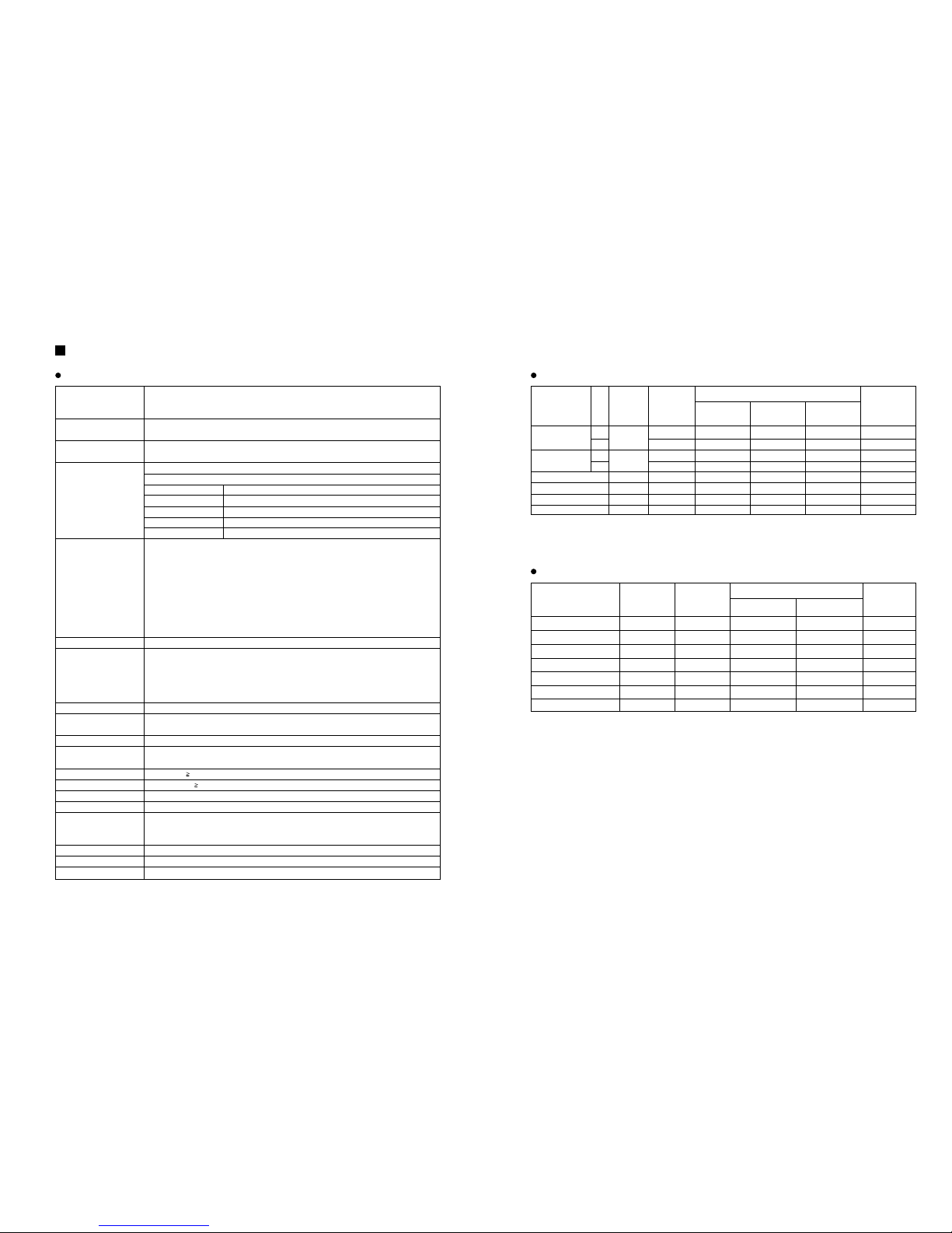
CH INPUT (Lo-Z) OFF 3 kΩ50–600ΩMics –62 dB (616 µV) –50 dB (2.45 mV) –20 dB (77.5 mV) XLR-3-31
(CH1–6) ON 600ΩLines –32 dB (19.5 mV) –20 dB (77.5 mV) +10 dB (2.45 V) type
CH INPUT (Hi-Z) OFF 10 kΩ50–600ΩMics –52 dB (1.95 mV) –40 dB (7.75 mV) –10 dB (245 mV) Phone jack
(CH1–6) ON 600ΩLines –22 dB (61.6 mV) –10 dB (245 mV) +20 dB (7.75 V) (TRS)*2
MIC INPUT (CH7, 8) 3 kΩ50–600ΩMics –62 dB (616 µV) –50 dB (2.45 mV) –20 dB (77.5 mV) XLR-3-31 type*2
LINE INPUT (CH7, 8) (L, R)
10 kΩ600ΩLine –22 dB (61.6 mV) –10 dB (245 mV) +20 dB (7.75 V) Phone jack
TAPE IN (L, R) 10 kΩ600ΩLine
–22 dBV (79.4 mV)
–10 dBV (316 mV) +17.8 dBV (7 V) Phono jack
AUX IN (L, R) 10 kΩ600ΩLine –22 dB (61.6 mV) –10 dB (245 mV) +20 dB (7.75 V) Phone jack*3
MAIN STEREO: 135 W+135 W/8Ω@0.5% THD at‹°kHz, 200 W+200 W/4Ω@0.5% THD at 1 kHz
MAIN BRIDGE: 400 W/8Ω@0.5% THD at 1 kHz
MONITOR: 135 W/8Ω@0.5% THD at 1 kHz, 200 W/4Ω@0.5% THD at 1 kHz
20 Hz–20 kHz +1 dB, –3 dB @1 W output into 8Ω(POWER AMP OUT)
20 Hz–20 kHz +1 dB, –3 dB @+4 dB output into 10 kΩ(MAIN OUT, MONITOR OUT, EFFECT OUT)
Less than 0.5% @20 Hz–20 kHz, 100 W output into 4Ω(POWER AMP OUT)
Less than 0.3% @20 Hz–20 kHz, +14 dB output into 10 kΩ(MAIN OUT, MONITOR OUT, EFFECT OUT)
–125 dB equivalent input noise, –68 dB residual output noise (POWER AMP OUT)
–95 dB residual output noise (MAIN OUT, MONITOR OUT, EFFECT OUT)
–80 dB (MAIN OUT) Master level control: nominal level, All channel level controls: minimum
–75 dB (MONITOR OUT) Master level control: nominal level, All channel level controls: minimum
–71 dB (MAIN OUT) Master level control: nominal level, 1 channel level control: nominal level
–84 dB (EFFECT OUT) Master level control: nominal level, All channel level controls: minimum
–64 dB (EFFECT OUT) Master level control: nominal level, 1 channel level control: nominal level
86 dB CH IN (Lo-Z) to POWER AMP OUT (CH1–6)
66 dB CH IN (Lo-Z) to MAIN OUT, MONITOR OUT (CH1–6)
72 dB CH IN (Lo-Z) to EFFECT OUT (CH1–6)
48 dB CH IN (Lo-Z) to REC OUT (CH1–6)
56 dB CH IN (Hi-Z) to MAIN OUT, MONITOR OUT (CH1–6)
26 dB AUX IN to MAIN OUT
24 dB TAPE IN to MAIN OUT
66 dB MIC IN to MAIN OUT (CH7–8)
26 dB LINE IN to MAIN OUT (CH7–8)
–65 dB adjacent input, –65 dB input to output
±15 dB Maximum
HIGH 10 kHz shelving
MID 2.5 kHz peaking
LOW 100 Hz shelving
* Turn over/roll-off frequency of shelving: 3 dB below maximum variable level.
5 POINTS LED METER (MAIN OUT L/R, MONITOR OUT)
7 bands (125, 250, 500, 1k, 2k, 4k, 8k Hz)
±12 dB Maximum (MAIN OUT, MONITOR OUT)
3 types (Vocal, L Hall, S Hall)
+48 V is supplied to electrically balanced inputs for powering condenser microphones via 6.8 kΩcurrent
limiting/isolation resisters.
Comp. : THD 0.5% (MAIN, MONITOR)
Turns on. : THD 0.5% (MAIN, MONITOR)
DIGITAL EFFECT MUTE : on/off
FC5 Foot switch
USA and Canada 120 V AC 60 Hz
Europe 230 V AC 50 Hz
Other 240 V AC 50 Hz
300 W
497x324x275 mm
17 kg
Maximum output power
Frequency response
Total harmonic distortion
Hum & noise
(Average, Rs=150Ω)
(with 20 Hz–20 kHz BPF)
Maximum voltage gain
(PAD: OFF)
Crosstalk at 1 kHz
Input channel equalization
Meters
Graphic equalizer
Internal digital effect
Phantom power
Limiter
LIMIT indicators
Foot switch
Optional accessories
Power requirement
Power consumption
Dimensions (WxHxD)
Weight
3
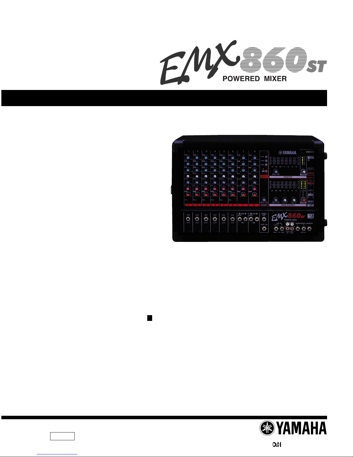
EMX860ST
SPECIFICATIONS
General specifications
Input connectors
Input specifications
Actual load
impedance
Input level
Sensitivity*1Nominal level Max. before
cliping
Connector
type
PAD Nominal
impedance
MAIN AMP OUT (L, R) (A, B) 0.1Ω4/8ΩSpeaker 37.7 W/4Ω(200 W/4Ω) Phone jack
MAIN BTL OUT 0.1Ω8ΩSpeaker 75.4 W/8Ω(400 W/8Ω) Phone jack
MONITOR AMP OUT (A, B) 0.1Ω8ΩSpeaker 37.7 W/4Ω(200 W/4Ω) Phone jack
MAIN OUT (L, R) 600Ω10 kΩLines +4 dB (1.23 V) +20 dB (7.75 V) Phone jack
MONITOR OUT 600Ω10 kΩLines +4 dB (1.23 V) +20 dB (7.75 V) Phone jack
EFFECT OUT 600Ω10 kΩLines +4 dB (1.23 V) +20 dB (7.75 V) Phone jack
REC OUT (1, 2) 600Ω10 kΩLines –10 dBV (316 mV) +10 dBV (3.16 V) Phono jack
Output connectors
Output specifications
Actual source
impedance
Output level
Nominal Max. before cliping Connector type
Nominal
impedance
• All output jacks are unbalanced.
• 0 dB=0.775 Vrms, 0 dBV=1 Vrms.
Specifications are subject to change without prior notice.
*1. Sensitivity is the lowest level that can produce an output of +4 db (1.23 V) or the nominal output level when the unit is set at maximum gain.
*2. Balanced.
*3. Unbalanced.
• 0 dB=0.775 Vrms, 0 dBV=1 Vrms.