Yamaha MG12/4 User manual

SERVICE MANUAL
■ CONTENTS
SPECIFICATIONS ......................................................... 3/5
DIMENSIONS ..................................................................... 7
PANEL LAYOUT ................................................. 8
MG12/4 CIRCUIT BOARD LAYOUT &WIRING............................... 12
MG16/4 CIRCUIT BOARD LAYOUT &WIRING............................... 14
MG12/4 DISASSEMBLY PROCEDURE ........ 16
MG16/4 DISASSEMBLY PROCEDURE ........ 21
IC BLOCK DIAGRAM ............................................ 26
CIRCUIT BOARDS ................................................. 27
INSPECTIONS ................................................................ 39/44
MG12/4 PARTS LIST
MG16/4 PARTS LIST
BLOCK DIAGRAM & LEVEL DIAGRAM
OVERALL CIRCUIT DIAGRAM
MG16/4
,
MIXING CONSOLE
MG12/4
Copyright (c) Yamaha Corporation. All rights reserved. PDF-K1411 ’05.06
PA 011779
MG12/4: 200304-24800
MG16/4: 200304-34800
(目次)
(総合仕様)
(寸法図)
(パネルレイアウト)
(MG12/4ユニットレイアウト&結線図)
(MG16/4ユニットレイアウト &結線図)
(MG12/4分解手順)
(MG16/4分解手順)
(ICブロック図)
(シート基板図)
(検査)
(ブロック& レベルダイアグラム)
(総回路図)
A manufacture number should use this
manual with goods of 9 or more figures.
(本マニュアルは、製造番号が9桁以上の商
品でご使用ください。)
The example of a manufacture number.
(製造番号例)
JCLJ01001
UCCLJ01001
CHNCLJ01001
_____________
9-11 figures
(9〜11桁)
The service manual of PA 011677 should
be used for the goods whose manufacture
number is 7 figures.
(製造番号が7桁の商品は、PA 011677 の
サービスマニュアルをご使用ください。)
The example of a manufacture number.
(製造番号例)
LK01001
_____________
7 figures
(7桁)

2
MG12/4
MG16/4
IMPORTANT NOTICE
This manual has been provided for the use of authorizedYamaha Retailers and their service personnel.It has been assumed
that basic service procedures inherent to the industry, and more specifically Yamaha Products, are already known and
understood by the users, and have therefore not been restated.
WARNING : Failure to follow appropriate service and safety procedures when servicing this product may result in
personal injury, destruction of expensive components and failure of the product to perform as
specified. For these reasons, we advise all Yamaha product owners that all service required should
be performed by an authorizedYamaha Retailer or the appointed service representative.
IMPORTANT : This presentation or sale of this manual to any individual or firm does not constitute authorization,
certification, recognition of any applicable technical capabilities, or establish a principal-agent
relationship of any form.
The data provided is believed to be accurate and applicable to the unit (s) indicated on the cover.The research engineering,
and service departments of Yamaha are continually striving to improveYamaha products. Modifications are, therefore,
inevitable and changes in specification are subject to change without notice or obligation to retrofit.Should any discrepancy
appear to exist, please contact the distributor’s Service Division.
WARNING : Static discharges can destroy expensive components. Discharge any static electricity your body
may have accumulated by grounding yourself to the ground bus in the unit (heavy gauge black wires
connect to this bus).
IMPORTANT : Turn the unit OFF during disassembly and parts replacement. Recheck all work before you apply
power to the unit.
WARNING : CHEMICAL CONTENT NOTICE !
The solder used in the production of this product contains LEAD. In addition, other electrical/electronic and/or plastic
(where applicable) components may also contain traces of chemicals found by the California Health and Welfare Agency
(and possibly other entities) to cause cancer and/or birth defects or other reproductive harm.
DO NOT PLACE SOLDER, ELECTRICAL/ELECTRONIC OR PLASTIC COMPONENTS IN YOUR MOUTH FOR ANY
REASON WHAT SO EVER!
Avoid prolonged, unprotected contact between solder and your skin!When soldering, do not inhale solder fumes or expose
eyes to solder/flux vapor!
If you come in contact with solder or components located inside the enclosure of this product, wash your hands before
handling food.
■WARNING
Components having special characteristics are marked Zand must be replaced with parts having specification equal to
those originally installed.
IMPORTANT NOTICE FOR THE UNITED KINGDOM
Connecting the Plug and Cord
IMPORTANT . The wires in this mains lead are coloured in accordance with the following code:
BLUE: NEUTRAL
BROWN: LIVE
As the colours of the wires in the mains lead of this apparatus may not correspond with the coloured markings identifying
the terminals in your plug proceed as follows:
The wire which is coloured BLUE must be connected to the terminal which is marked with the letter N or coloured BLACK.
The wire which is coloured BROWN must be connected to the terminal which is marked with the letter L or coloured RED.
Making sure that neither core is connected to the earth terminal of the three pin plug.
Z印の部品は、安全を維持するために重要な部品です。交換する場合は、安全のために必ず指定の部品をご使用ください。

3
MG12/4
MG16/4
■SPECIFICATIONS
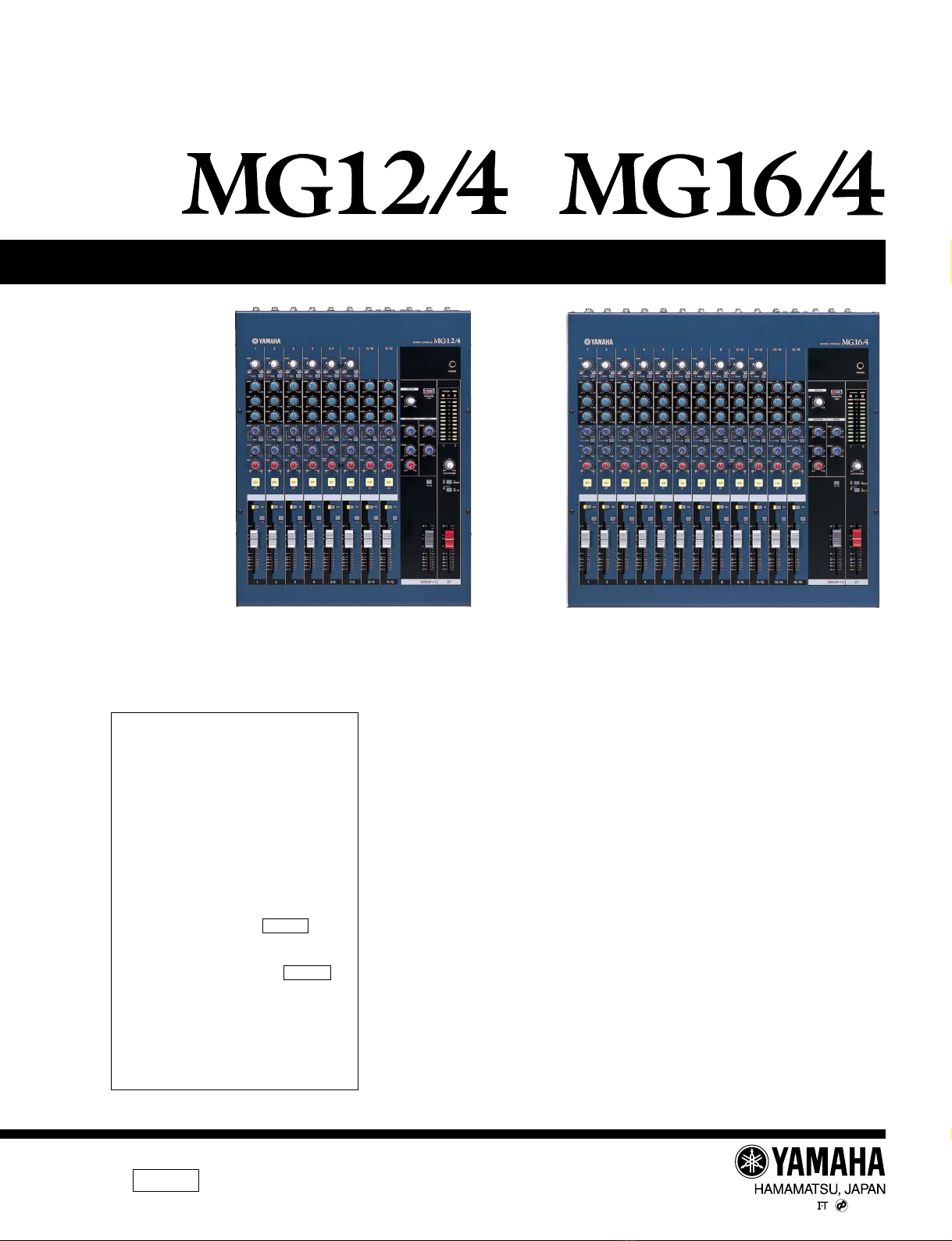
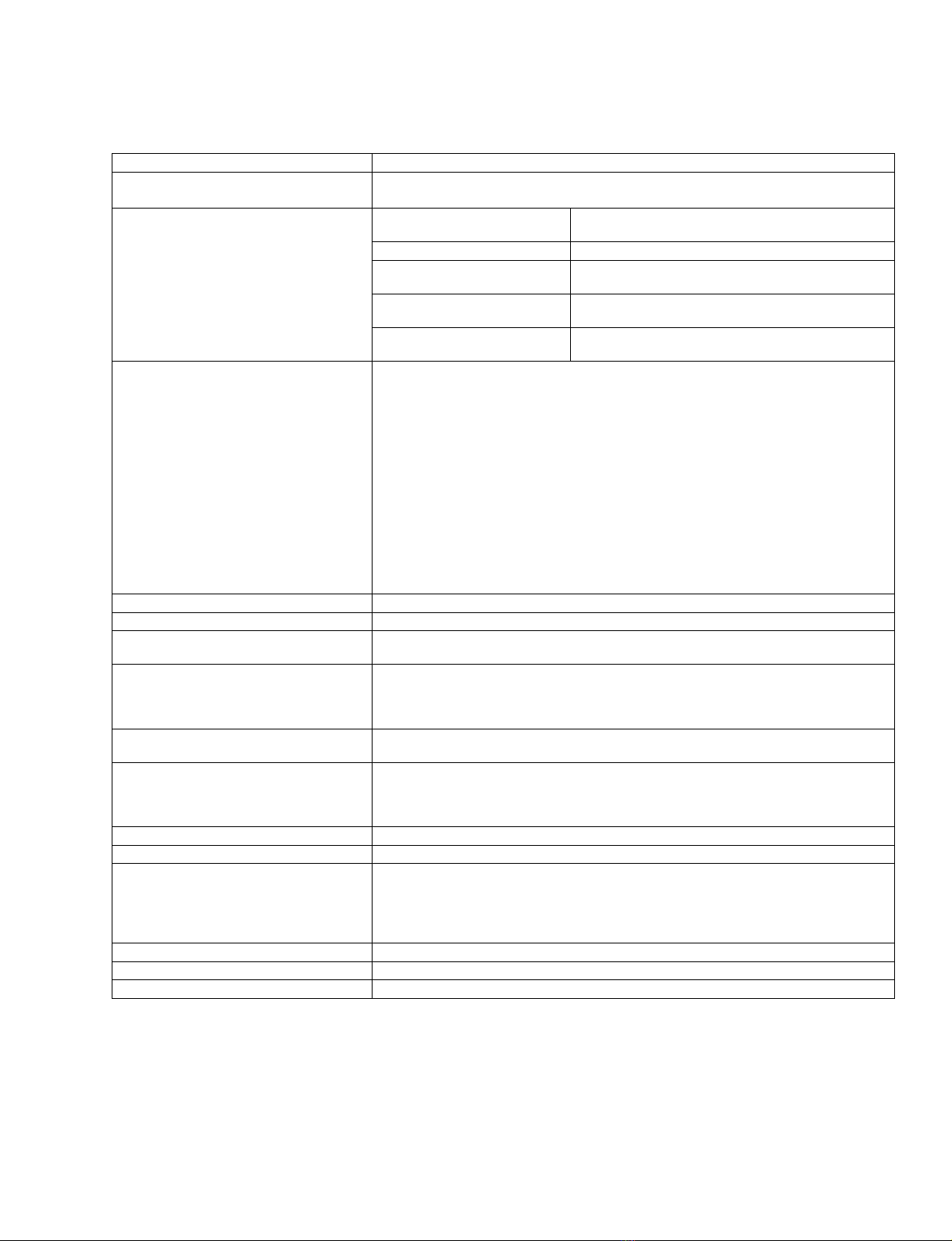
General Specifications
Where 0 dBu = 0.775 V and 0 dBV = 1 V
1
Measured with 12.7 kHz, –6 dB/oct. low pass filter (equivalent to 20 kHz, – ∞filter).
(CH MIC INPUT to ST, GROUP OUT/AUX, EFFECT SEND)
2
Turning PAN/BAL to left or right.
3
Shelving turnover/rolloff frequency:3 dB before maximum cut or boost.
Frequency Characteristics (ST OUT) 20 Hz–20 kHz +1 dB, –3 dB @+4 dBu, 600 Ω(with gain control at minimum level)
Total Harmonic Distortion (ST OUT) 0.1 % (THD+N) @+14 dBu, 20 Hz–20 kHz, 600 Ω(MG12/4: CHs 1 to 4, MG16/4: CHs 1 to 8)
(MG12/4: CHs 1 to 4, MG16/4: CHs 1 to 8)
(with gain control at maximum level)
Hum and Noise
1
–128 dBu Equivalent input noise 150 Ω(MG12/4:CHs 1 to 4,
MG16/4: CHs 1 to 8)
–100 dBu Residual output noise (ST OUT)
–88 dBu (92 dB S/N) ST, GROUP Master fader at nominal level and all Ch
assign SW’s off.
–81 dBu (85 dB S/N) AUX master control at nominal level;all channel mix
controls at minimum level.
–64 dBu (68 dB S/N) ST, GROUP Master fader and one Ch fader at nominal
level.
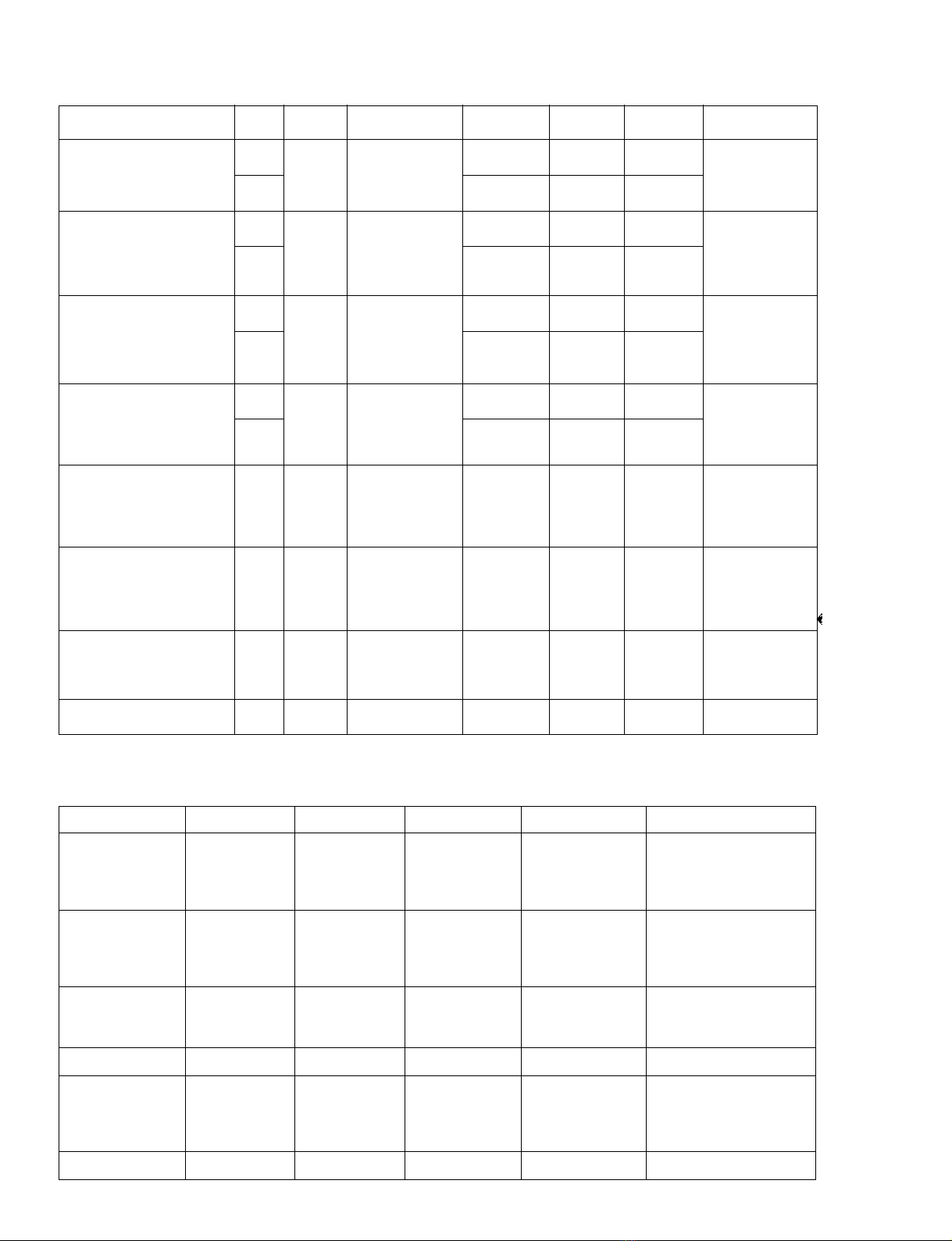
Maximum Voltage Gain
2
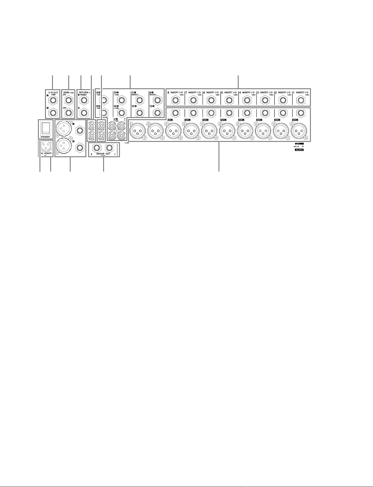
60 dB CH MIC INPUT →CH INSERT OUT
84 dB CH MIC INPUT →GROUP OUT/ST OUT (CH to ST)
94 dB CH MIC INPUT →ST OUT (GROUP to ST)
62.2 dB CH MIC INPUT →REC OUT (CH to ST)
76 dB CH MIC INPUT →AUX SEND (PRE)
86 dB CH MIC INPUT →AUX SEND (POST)
58 dB CH LINE INPUT →GROUP OUT/ST OUT (CH to ST)
84 dB ST CH MIC INPUT →GROUP OUT/ST OUT (CH to ST)
58 dB ST CH LINE INPUT →GROUP OUT/ST OUT (ST CH to ST)
47 dB ST CH LINE INPUT →AUX SEND (PRE)
57 dB ST CH LINE INPUT →AUX SEND (POST)
34 dB ST CH INPUT →GROUP OUT/ST OUT (ST CH to ST)
16 dB RETURN →ST OUT
9 dB RETURN →AUX SEND
27.8 dB 2TR INPUT →ST OUT
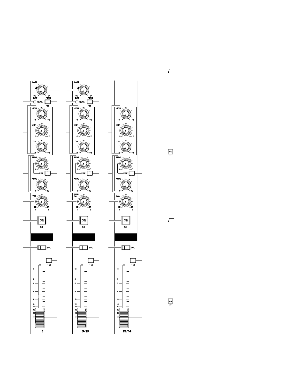
Monaural/Stereo Input Gain Control 44 dB variable
Monaural/Stereo High Pass Filter 80 Hz 12 dB/octave
Crosstalk (1 kHz) –70 dB between input channels
–70 dB between input/output channels (CH INPUT)
Monaural/Stereo Input Channel Equalization:
Max.Variation
3
±15 dB
HIGH 10 kHz shelving
MID 2.5 kHz peaking
LOW 100 Hz shelving
Monaural/Stereo Input Peak Indicator On each channel: red indicator lights if post-EQ signal (on ST channels, if either post-EQ sig-
nal or post-mic-amp signal) comes within 3 dB of the clipping level.
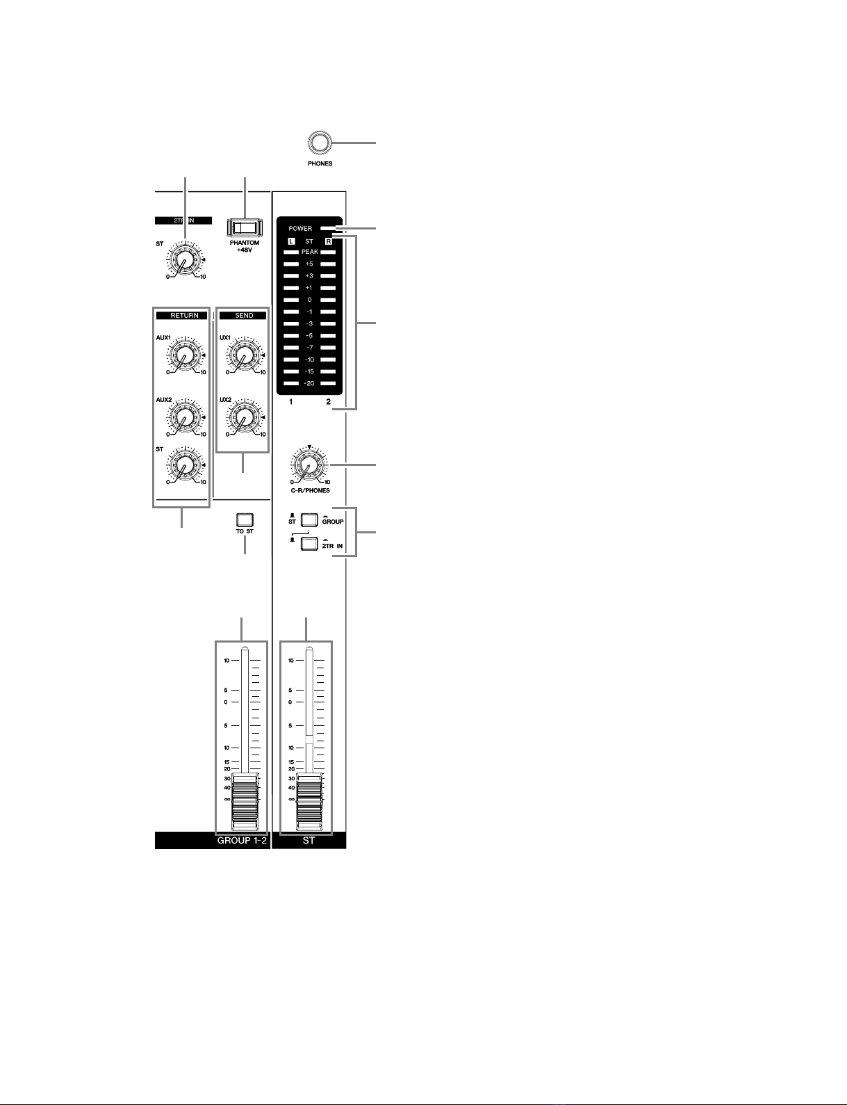
Level Meters
Two 12-point LED meters
Peak point: red indicator
+5, +3, +1, and 0 points: yellow indicators
–1, –3, –5, –7, –10, –15, –20: green indicators
Phantom +48 VDC Power (Balanced input) Supplied when Phantom +48 V switch is ON.
Included Accessory Power adaptor (PA-20)
Power Supply
USA and Canada: 120 V AC, 60 Hz
Europe: 230V AC, 50 Hz
Australia: 240 V AC, 50 Hz
Korea: 220 V AC, 60 Hz
China: 220 V AC, 50 Hz
Power Consumption MG16/4: 36 W MG12/4: 29 W
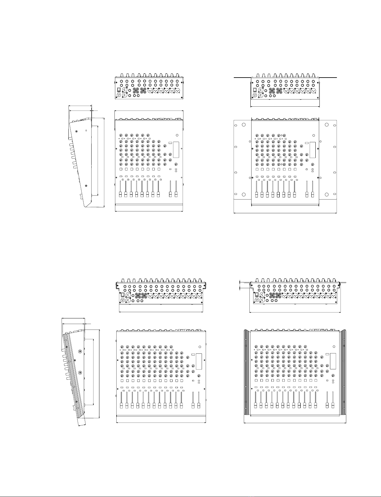
Max. Dimensions (W ×H ×D) MG16/4: 423 ×108 ×416.6 mm MG12/4: 322 ×108 ×416.6 mm
Weight MG16/4: 5.2 kg MG12/4: 5.0 kg
■

4
MG12/4
MG16/4
Input Specifications
Where 0 dBu = 0.775 V and 0 dBV= 1 V
* Input sensitivity: the lowest level that will produce the nominal output level when the unit is set to maximum gain.
Output Specifications
Where 0 dBu = 0.775 V and 0 dBV= 1 V
Input Connector Gain Input
Impedance Appropriate
Impedance Sensitivity* Rated Level Max. Before
Clipping Connector
Specifications
MIC INPUT
(MG16/4: CHs 1 to 8)
(MG12/4: CHs 1 to 4)
–60 3 k
Ω
50–600
Ω
mic
–80 dBu
(0.078 mV) –60 dBu
(0.775 mV) –40 dBu
(7.75 mV) XLR-3-31 type (balanced)
–16 –36 dBu
(12.3 mV) –16 dBu
(123 mV) +4 dBu
(1.23 V)
LINE INPUT
(MG16/4: CHs 1 to 8)
(MG12/4: CHs 1 to 4)
–34 10 k
Ω
600
Ω
line
–54 dBu
(1.55 mV) –34 dBu
(15.5 mV) –14 dBu
(155 mV) Phone jack (TRS)
(balanced [T: hot; R: cold;
S: ground])
+10 –10 dBu
(245 mV) +10 dBu
(2.45 V) +30 dBu
(24.5 V)
ST CH MIC INPUT
(MG16/4: CH9(L)/CH10(R),
CH11(L)/CH12(R))
(MG12/4: CH5(L)/CH6(R),
CH7(L)/CH8(R))
–60 3 k
Ω
50–600
Ω
mic
–80 dBu
(0.078 mV) –60 dBu
(0.775 mV) –40 dBu
(7.75 mV) XLR-3-31 type (balanced)
–16 –36 dBu
(12.3 mV) –16 dBu
(123 mV) –10 dBu
(245 mV)
ST CH LINE INPUT
(MG16/4: CH9(L)/CH10(R),
CH11(L)/CH12(R))
(MG12/4: CH5(L)/CH6(R),
CH7(L)/CH8(R))
–34 10 k
Ω
600
Ω
line
–54 dBu
(1.55 mV) –34 dBu
(15.5 mV) –14 dBu
(155 mV) Phone jack (unbalanced)
+10 –10 dBu
(245 mV) +10 dBu
(2.45 V) +30 dBu
(24.5 V)
ST CH INPUT
(MG16/4: CH13(L)/CH14(R),
CH15(L)/CH16(R))
(MG12/4: CH9(L)/CH10(R),
CH11(L)/CH12(R))
10 k
Ω
600
Ω
line –30 dBu
(24.5 mV) –10 dBu
(245 mV) +10 dBu
(2.45 V) Phone jack (unbalanced);
RCA pin jack
CH INSERT IN
(MG16/4: CHs 1 to 8)
(MG12/4: CHs 1 to 4) 10 k
Ω
600
Ω
line –20 dBu
(77.5 mV) 0 dBu
(0.775 V) +20 dBu
(7.75 V) Phone jack (TRS)
(unbalanced [T: out; R: in;
S: ground])
RETURN (L, R) 10 k
Ω
600
Ω
line –12 dBu
(195 mV) +4 dBu
(1.23 V) +24 dBu
(12.3 V) Phone jack (TRS) (unbalanced
[T: hot; S: ground])
2TR IN (L, R) 10 k
Ω
600
Ω
line –26 dBV
(50.1 mV) –10 dBV
(316 mV) +10 dBV
(3.16 V) RCA pin jack
Output Connectors Output
Impedance Appropriate
Impedance Rated Level Max. Before
Clipping Connector Specifications
ST OUT (L, R) 150
Ω
600
Ω
line +4 dBu (1.23 V) +24 dBu (12.3 V) XLR-3-32 type (balanced)
Phone jack (TRS)
(balanced [T: hot; R: cold; S: ground])
GROUP OUT (1-2)
AUX SEND (1-2) 150
Ω
10 k
Ω
line +4 dBu (1.23 V) +20 dBu (7.75 V) Phone jack (TRS)
(impedance balanced [T: hot; R: cold; S:
ground])
CH INSERT OUT
(MG16/4: CHs 1 to 8)
(MG12/4: CHs 1 to 4) 150
Ω
10 k
Ω
line 0 dBu (0.775 V) +20 dBu (7.75 V) Phone jack (TRS)
(unbalanced [T: out; R: in; S: ground])
REC OUT (L, R) 600
Ω
10 k
Ω
line –10 dBV (316 mV) +10 dBV (3.16 V) RCA pin jack
C-R OUT (L, R) 150
Ω
10 k
Ω
line +4 dBu (1.23 V) +20 dBu (7.75 V) Phone jack (TRS)
(impedance balanced [T: hot; R: cold; S:
ground])
PHONES 100
Ω
40
Ω
phone 3 mW 75 mW Stereo phone jack
■
■

5
MG12/4
MG16/4
■ 総合仕様
■一般仕様
* 0 dBu=0.775 V、
0 dBV=1 V とする
*1 @12.7 kHz, –6 dB/oct. のローパスフィルターにて測定
(
@20 kHz, –∞dB/oct. フィルターに相当)
(
CH MIC INPUT to ST, GROUP OUT/AUX, EFFECT SEND)
*2 PAN/BAL 左か右へ回す
*3 シェルビングタイプのターンオーバー/ロールオフ周波数:最大可変幅に対し3 dB 下がったポイント
周波数特性(STOUT)
20 Hz 〜
20 kHz +1 dB, –3 dB
@
+4 dBu(*)
, 600 Ω(
GAINコントロール=最小レベル)
全高調波歪率(STOUT)
0.1 %(
THD+N)
@
+14 dBu, 20 Hz 〜
20 kHz, 600 Ω
(
GAIN コントロール=最大レベル)
ハム& ノイズ
*1
–128 dBu 入力換算ノイズ
150 Ω
(
MG12/4 CH1〜4、
MG16/4 CH1 〜
8)
(
MG12/4 CH1〜4、
MG16/4 CH1 〜
8)
–100 dBu 残留ノイズ
(ST OUT)
–88 dBu(
92 dB S/N)
ST OUT、
GROUP OUT
マスターフェーダー=ノミナル、
全チャンネルアサイン
スイッチ=OFF
–81 dBu(
85 dB S/N)
AUX マスターコントロール=ノミナル、全チャンネル
ミックスコントロール=最小レベル
–64 dBu(
68 dB S/N)
ST OUT、
GROUP OUT
マスターフェーダー&
1チャンネルフェーダー=ノミナル
(MG12/4 CH1 〜4、MG16/4 CH1 〜8)
最大電圧ゲイン
*2
60 dB
CH MIC INPUT →
CH INSERT OUT
84 dB
CH MIC INPUT →
GROUP OUT/ST OUT(
CH to ST)
94 dB
CH MIC INPUT →
ST OUT(
GROUP to ST)
62.2 dB
CH MIC INPUT →
REC OUT(
CH to ST)
76 dB
CH MIC INPUT →AUX SEND(
PRE)
86 dB
CH MIC INPUT →
AUX SEND(
POST)
58 dB
CH LINE INPUT →GROUP OUT/ST OUT(
CH to ST)
84 dB
ST CH MIC INPUT →GROUP OUT/ST OUT(
CH to ST)
58 dB
ST CH LINE INPUT →GROUP OUT/ST OUT(
ST CH to ST)
47 dB
ST CH LINE INPUT →AUX SEND(
PRE)
57 dB
ST CH LINE INPUT →
AUX SEND(
POST)
34 dB
ST CH INPUT →GROUP OUT/ST OUT(
ST CH to ST)
16 dB RETURN →ST OUT
9 dB RETURN →AUX SEND
27.8 dB
2TR INPUT →ST OUT
モノラル、ステレオインプットゲインコントロール
44 dB 可変
モノラル、ステレオハイパスフィルター 80 Hz 12 dB/octave
クロストーク
(1 kHz) –70 dB 入力チャンネル間
–70 dB 入出力チャンネル間(
CH INPUT)
モノラル、ステレオ入力チャンネルイコライザー
特性最大可変幅
*3
±15 dB
HIGH 10 kHz シェルビングタイプ
MID 2.5 kHz ピーキングタイプ
LOW 100 Hz シェルビングタイプ
モノラル、ステレオインプットピークインジケーター
各チャンネル、イコライザー(およびMIC アンプ:
ST CH)の後段において、どちらか
一方の信号レベルがクリッピングの手前3 dB に達すると赤く点灯
レベルメーター 12 ポイントLED ×2 [ステレオ(
L、
R)]
ピーク時:赤のインジケーター
+5、
+3、
+1、
0:黄のインジケーター
–1、
–3、
–5、
–7、
–10、
–15、
–20:緑のインジケータ
ファンタム電源+48 VDC(バランス入力) PHANTOM +48 V スイッチ=ON で供給
付属品 電源アダプター
(PA-20)
電源 100 V AC 50/60 Hz
消費電力 MG16/4: 36 W MG12/4: 29 W
最大外形寸法(
W×H×D) MG16/4: W423 ×H108 ×D416.6 mm MG12/4: W322 ×H108 ×D416.6 mm
重量 MG16/4: 5.2 kg MG12/4: 5.0 kg

6
MG12/4
MG16/4
■入力仕様
*0dBu=0.775V 、
0dBV=1Vとする
*1
入力感度:最大ゲイン測定時に定格出力が得られる最小レベル
■出力仕様
* 0 dBu=0.775 V、
0 dBV=1 V とする
入力端子名称 ゲイン 入力イン
ピーダンス
適合インピーダンス 感度
*1
規定レベル 最大ノンク
リップレベル 端子仕様
MIC INPUT
(MG16/4:
CH1 〜8)
(MG12/4:
CH1 〜4)
–60 3 kΩ 50 〜600 Ωマイク–80 dBu
(
0.078 mV)
–60 dBu
(
0.775 mV)–40 dBu
(
7.75 mV) XLR-3-31タイプ
(バランス型)
–16 –36 dBu
(
12.3 mV) –16 dBu
(
123 mV) +4 dBu
(
1.23 V)
LINE INPUT
(MG16/4:
CH1 〜8)
(MG12/4:
CH1 〜4)
–34 10 kΩ 600 Ωライン –54 dBu
(
1.55 mV) –34 dBu
(
15.5 mV)–14 dBu
(
155 mV) フォーンジャック
(
TRS)
(バランス
型[
T:ホット、
R: コールド、
S:グラウンド])
+10 –10 dBu
(
245 mV) +10 dBu
(
2.45 V) +30 dBu
(
24.5 V)
ST CH MIC INPUT
(MG16/4:CH9(L)/CH10(R)、
CH11(L)/CH12(R))
(MG12/4:CH5(L)/CH6(R)、
CH7(L)/CH8(R))
–60 3 kΩ 50 〜600 Ωマイク–80 dBu
(
0.078 mV) –60 dBu
(
0.775 mV)–40 dBu
(
7.75 mV) XLR-3-31タイプ
(バランス型)
–16 –36 dBu
(
12.3 mV) –16 dBu
(
123 mV) –10 dBu
(
245 mV)
ST CH LINE INPUT
(MG16/4:
CH9(L)/CH10(R)、
CH11(L)/CH12(R))
(MG12/4:
CH5(L)/CH6(R)、
CH7(L)/CH8(R))
–34 10 kΩ 600 Ωライン –54 dBu
(
1.55 mV) –34 dBu
(
15.5 mV)–14 dBu
(
155 mV) フォーンジャック
(アンバランス型)
+10 –10 dBu
(245 mV) +10 dBu
(
2.45 V) +30 dBu
(
24.5 V)
ST CH INPUT
(MG16/4:
CH13(L)/CH14(R)、
CH15(L)/CH16(R))
(MG12/4:
CH9(L)/CH10(R)、
CH11(L)/CH12(R))
10 kΩ 600 Ωライン –30 dBu
(
24.5 mV) –10 dBu
(
245 mV) +10 dBu
(
2.45 V) フォーンジャック
(アンバランス型)、
RCA ピンジャック
CH INSERT IN
(MG16/4:
CH1 〜8)
(MG12/4:
CH1 〜4)
10 kΩ 600 Ωライン –20 dBu
(
77.5 mV) 0 dBu
(
0.775 V) +20 dBu
(
7.75 V) フォーンジャック
(
TRS)
(アンバランス型
[
T:アウト、
R:イ
ン、
S:グラウンド]
)
RETURN (L、R) 10 kΩ 600 Ωライン –12 dBu
(
195 mV) +4 dBu
(
1.23 V) +24 dBu
(
12.3 V) フォーンジャック
(
TRS)(アンバラン
ス型[
T: ホット、
S: グラウンド])
2TR IN (L、
R) 10 kΩ 600 Ωライン –26 dBV
(
50.1 mV) –10 dBV
(
316 mV) +10 dBV
(
3.16 V)
RCA ピンジャック
出力端子名称
出力インピーダンス適合インピーダンス
規定レベル
最大ノンクリップレベル
端子仕様
ST OUT (L、
R)
150 Ω 600 Ωライン +4 dBu(
1.23 V) +24 dBu(
12.3 V)
XLR-3-32タイプ(バランス型)
フォーンジャック(
TRS)
(バランス型[
T: ホット、
R: コールド、
S:グラウンド])
GROUP OUT (1-2)
AUX SEND (1-2) 150 Ω 10 kΩライン +4 dBu(
1.23 V) +20 dBu(
7.75 V) フォーンジャック(
TRS)
(インピーダンスバランス型
[
T:ホット、
R:コールド、
S: グラウンド])
CH INSERT OUT
(MG16/4:
CH1 〜8)
(MG12/4:
CH1 〜4)
150 Ω 10 kΩライン 0 dBu(
0.775 V) +20 dBu(
7.75 V) フォーンジャック(
TRS)
(アンバランス型[
T: アウト、
R:イン、
S: グラウンド])
REC OUT (L
、
R) 600 Ω 10 k Ωライン –10 dBV (316 mV) +10 dBV (3.16 V) RCAピンジャック
C-R OUT (L 150 Ω 10 k Ω
ライン+4 dBu (1.23 V) +20 dBu (7.75 V)
フォーンジャック(
TRS)
(インピーダンスバランス型
[
T:ホット、
R:コールド、
S: グラウンド])
PHONES 100 Ω
40 Ωフォーン3 mW 75 mW ステレオフォーンジャック
、
R)

7
MG12/4
MG16/4
■DIMENSIONS
■MG16/4
■MG12/4
393
31.5
309.6
D 416.6
H 108
101.3 3
W 423
428
27.5
480
When mounted on rack
317.4
D 416.6
325.6
102.6 2
H 108
W 322
480
322
When mounted on rack
Units : mm
(寸法図)
(ラック取り付け時)
(ラック取り付け時)
(単位)

8
MG12/4
MG16/4
q[GAIN] Control
w[PEAK] Indicator
e[
80
] Switch (High Pass Filter)
rEqualizer ([HIGH], [MID], [LOW])
t[AUX1] and [AUX2] Controls
y[PRE] Switch
u[PAN] Control (MG16/4: CHs 1 to 8. MG12/
4: CHs 1 to 4)
[PAN/BAL] Control (MG16/4: CHs 9/10 and
11/12. MG12/4: CHs 5/6 and 7/8)
[BAL] Control (MG16/4: CHs 13/14 and 15/
16. MG12/4: CHs 9/10 and 11/12)
i[ ] ST Switch
o[PFL] (Pre-Fader Listen) Switch
!0 [GROUP] Switch
!1 Channel Fader
■PANEL LAYOUT
Note: Within this manual, all panel illustrations show the MG16/4 panel.
(パネルイラストはすべてMG16/4です。)
Channels
1 to 8 (MG16/4)
1 to 4 (MG12/4)
(Monaural)
Channels
9/10 and 11/12
(MG16/4)
5/6 and 7/8
(MG12/4)
(Stereo)
Channels
13/14 and 15/16
(MG16/4)
9/10 and 11/12
(MG12/4)
(Stereo)
w
q
ewe
tytyty
oo
!0 !0
!1 !1
o
!0
!1
r r r
u u u
i i i
■Channel Control Section
(パネルレイアウト)
(チャンネルコントロール部)
q[GAIN]コントロール
w[PEAK]インジケーター
e[
80
](ハイパスフィルター)スイッチ
rイコライザー([HIGH]、[MID]、[LOW])
t[AUX1]、[AUX2]コントロール
y[PRE]スイッチ
u[PAN]コントロール(MG16/4:CH1〜 8、
MG12/4:CH1〜4)
[PAN/BAL]コントロール(MG16/4:CH9/
10、11/12、MG12/4:CH5/6、7/8)
[BAL]コントロール(MG16/4:CH13/14、
15/16、MG12/4:CH9/10、11/12)
i[ ]STスイッチ
o[PFL]
(プリフェーダーリッスン)スイッチ
!0 [GROUP]スイッチ
!1 チャンネルフェーダー

9
MG12/4
MG16/4
q[ST] Master Fader
w[GROUP 1-2] Fader
e[ TO ST ] Switch
rMaster SEND ([AUX1] and [AUX2] Controls)
tRETURN ([AUX1], [AUX2], and [ST] Controls)
y[2TR IN] Control
u[PHANTOM +48V] Switch
iLevel-Meter Signal Switches
(ST-GROUP Toggle Switch and 2TR IN Switch)
o[C-R/PHONES] Control
!0 Level Meter
!1 [POWER] Indicator
!2 [PHONES] jack
yu
!2
!1
!0
o
i
t
e
r
wq
■Master Control Section(マスターコントロール部)
q[ST]マスターフェーダー
w[GROUP1-2]フェーダー
e[TOST]スイッチ
rSENDマスター
([AUX1]、[AUX2]コントロール)
tRETURN
([AUX1]、[AUX2]コントロール、[ST]コントロール)
y[2TRIN]コントロール
u[PHANTOM+48V]スイッチ
iレベルメーター信号切り替えスイッチ
(ST-GROUP切り替えスイッチ、2TRINスイッチ)
o[C-R/PHONES]コントロール
!0 レベルメーター
!1 [POWER]インジケーター
!2 [PHONES]端子

10
MG12/4
MG16/4
qChannel Input jacks
[MIC] jacks (MG16/4: CHs 1 to 8, 9/10, 11/12.
MG12/4: CHs 1 to 4, 5/6, 7/8)
[LINE] jacks (MG16/4: CHs 1 to 8. MG12/4: CHs
1 to 4)
w[INSERT I/O] Jacks
(MG16/4: CHs 1 to 8. MG12/4: CHs 1 to 4)
eChannel Input jacks
Phone type (MG16/4: CHs 9/10 to 15/16. MG12/4:
CHs 5/6 to 11/12)
RCA pin type (MG16/4: CHs 13/14, 15/16. MG12/
4: CHs 9/10, 11/12)
r[GROUP OUT] (1, 2) Jacks
t[ST OUT] (L, R) Jacks
y[C-R OUT] Jacks
u[SEND] Jacks
i[RETURN L] (MONO), [RETURN R] Jacks
o[REC OUT] (L, R) Jacks
!0 [2TR IN] Jacks
!1 [POWER] Switch
!2 [AC ADAPTOR IN] Connector
yui
o!0 e
!1 !2 tr q
w
■Rear Input/Output Section
(リア入出力部)
qチャンネルINPUT端子
[MIC]端子(MG16/4:CH1〜 8、9/10、11/12、
MG12/4:CH1〜4、5/6、7/8)
[LINE]端子(MG16/4:CH1〜8、MG12/4:CH
1〜4)
w[INSERTI/O]端子
(MG16/4:CH1〜8、MG12/4:CH1 〜4)
eチャンネルINPUT端子
フォーンタイプ(MG16/4:CH9〜16、
MG12/4:CH5〜12)
RCAピンタイプ(MG16/4:CH13〜 16、
MG12/4:CH9〜12)
r[GROUPOUT](1、2)端子
t[STOUT](L、R)端子
y[C-ROUT]端子
u[SEND]端子
i[RETURNL](MONO)、[RETURNR]端子
o[RECOUT](L、R)端子
!0 [2TRIN]端子
!1 [電源]スイッチ
!2 [ACADAPTORIN]端子

11
MG12/4
MG16/4
Connector Polarities
* These jacks will also accept connection to monaural phone plugs.If you use monaural plugs, the connection will be unbalanced.
MIC INPUT, ST OUT Pin 1: Ground
Pin 2: Hot (+)
Pin 3: Cold (–)
LINE INPUT (monaural channels),
GROUP OUT, ST OUT, C-R OUT
AUX1, AUX2 *
Tip: Hot (+)
Ring: Cold (–)
Sleeve: Ground
INSERT I/O Tip: Output
Ring: Input
Sleeve: Ground
PHONES Tip: L
Ring: R
Sleeve: Ground
RETURN
LINE INPUT (stereo channels) Tip: Hot
Sleeve: Ground
INPUT OUTPUT
Ring
Sleeve Tip
Sleeve Tip
端子接続の極性
*これらの端子に、モノラルタイプのフォーン端子を使用することもできます。その場合は、アンバランスになります。
MIC INPUT、
ST OUT ピン1:グラウンド
ピン
2:ホット(
+)
ピン
3:コールド(
–)
LINE INPUT(モノラルチャンネル)、
GROUP OUT、
ST OUT、
C-R OUT
AUX 1、
AUX 2
*
チップ:ホット(
+)
リング:コールド(
–)
スリーブ:グラウンド
INSERT I/O チップ:
Output
リング:
Input
スリーブ:グラウンド
PHONES チップ:
L
リング:
R
スリーブ:グラウンド
RETURN
LINE INPUT (ステレオチャンネル) チップ:ホット
スリーブ:グラウンド
INPUT OUTPUT
スリーブ チップ
リング
スリーブ チップ

12
MG12/4
MG16/4
Shrink tube (Seven places)
(熱収縮チューブ:7箇所)
Red
アカ
Brown
チャ
Black
クロ
WA595400
WE735800
■MG12/4 CIRCUIT BOARD LAYOUT & WIRING
PS
●Power switch and AC connector wiring
MAIN
JACK 1/2
JACK 1/2 JACK 2/2
(MG12/4ユニットレイアウト&結線図)
(電源スイッチとACコネクタの結線)

13
MG12/4
MG16/4
WC703300 (7 places)
CN571 (JACK 1/2 circuit board) --- CN501 (MAIN circuit board)
CN771 (JACK 1/2 circuit board) --- CN701 (MAIN circuit board)
CN971 (JACK 1/2 circuit board) --- CN901 (MAIN circuit board)
CNA71 (JACK 1/2 circuit board) --- CNA01 (MAIN circuit board)
CND71 (JACK 1/2 circuit board) --- CND01 (MAIN circuit board)
CNE71 (JACK 1/2 circuit board) --- CNE01 (MAIN circuit board)
CNG71 (JACK 1/2 circuit board) --- CNG01 (MAIN circuit board)
MAIN circuit board
WE521500 MAIN circuit board
WE521500 JACK 2/2 circuit board
WE675700
CNH02
JACK 1/2 circuit board
WE675700 WD361600CNH01 CNF01
●MAIN circuit board and JACK circuit board wiring
●Wiring to PS circuit board
WE735800 WD361600 CN02
PS circuit board
WE522200
CN01
(MAINシートとJACKシートの結線)
(PSシートへの結線)

14
MG12/4
MG16/4
Shrink tube (Seven places)
(熱収縮チューブ:7箇所)
Red
アカ
Brown
チャ
Black
クロ
WA595400
WE735800
■MG16/4 CIRCUIT BOARD LAYOUT & WIRING
PS
MAIN
●Power switch and AC connector wiring
JACK 1/2
JACK 2/2
JACK 1/2
(MG16/4ユニットレイアウト&結線図)
(電源スイッチとACコネクタの結線)

15
MG12/4
MG16/4
WE735800 WD361600 CN02
PS circuit board
WE522200
CN01
WC703300 (9 places)
CN171 (JACK 1/2 circuit board) --- CN101 (MAIN circuit board)
CN371 (JACK 1/2 circuit board) --- CN301 (MAIN circuit board)
CN571 (JACK 1/2 circuit board) --- CN501 (MAIN circuit board)
CN771 (JACK 1/2 circuit board) --- CN701 (MAIN circuit board)
CN971 (JACK 1/2 circuit board) --- CN901 (MAIN circuit board)
CNA71 (JACK 1/2 circuit board) --- CNA01 (MAIN circuit board)
CND71 (JACK 1/2 circuit board) --- CND01 (MAIN circuit board)
CNE71 (JACK 1/2 circuit board) --- CNE01 (MAIN circuit board)
CNG71 (JACK 1/2 circuit board) --- CNG01 (MAIN circuit board)
MAIN circuit board
WE521600 MAIN circuit board
WE521600 JACK 2/2 circuit board
WE573100
CNH02
JACK 1/2 circuit board
WE573100 WD361600CNH01 CNF01
●MAIN circuit board and JACK circuit board wiring
●Wiring to PS circuit board
(MAINシートとJACKシートの結線)
(PSシートへの結線)

16
MG12/4
MG16/4
2. Bottom Cover
(Time required : About 3 min.)
2-1. Remove the rack mount angle L and R.
(See procedure 1)
2-2. Remove the eight (8) screws marked [500]. The bottom
cover can then be removed. (Fig. 1)
1. Rack Mount Angle
(Time required : About 1 min.)
1-1. Remove the two (2) screws marked [510A]. The rack
mount angle L can then be removed. (Fig. 1)
1-2. Remove the two (2) screws marked [510B]. The rack
mount angle R can then be removed. (Fig. 1)
Rack mount angle R
Rack mount angle L
(Fig. 1)
[430]: Bind Head Tapping Screw-S 3.0 x 6 MFZN2B3 (WE877800)
[500]: Bind Head Tapping Screw-S 3.0 x 6 MFZN2B3 (WE877800)
[510]: Bind Head Screw 4.0 x 8 MFZN2B3 (WE969000)
■MG12/4 DISASSEMBLY PROCEDURE
(分解手順)
[510A]
[510A]
[500]
[500]
[510B]
[510B]
[500]
[500]
[500] [500][430A] [430C]
[500] [500]
Bottom cover
2. ボトムカバー (所要時間:約 3 分 )
2-1. ラックアングルL、Rを外します。(1項参照)
2-2. [500]のネジ8本を外し、ボトムカバーを外します。
(図1)
1. ラックアングル (所要時間:約 1 分 )
1-1. [510A]のネジ2本を外し、ラックアングルLを外しま
す。(図1)
1-2. [510B]のネジ2本を外し、ラックアングルRを外しま
す。(図1)
(ラックアングルL)
(ボトムカバー)
(ラックアングルR)
Sタイト+BIND
Sタイト+BIND
小ネジ+BIND
(図1)

17
MG12/4
MG16/4
3. PS Circuit Board
(Time required : About 4 min.)
3-1. Remove the rack mount angle L and R.
(See procedure 1)
3-2. Remove the bottom cover. (See procedure 2)
3-3. Remove the two (2) screws marked [480]. The PS circuit
board and heat sink can then be removed. (Fig. 2)
* Replacing any part on the PS circuit board requires
removal of the heat sink as well. Use the following
procedure to remove the heat sink.
3-4. Remove the two (2) screws marked [A] fixing IC01 and
IC05. (Photo 1)
3-5. Remove the three (3) screws marked [B]. (Photo 1)
3-6. Remove the solder IC02, IC03 and Q01. The heat sink
can then be removed from the PS circuit board. (Photo 1)
4. Side Cover
(Time required : About 5 minutes each.)
4-1. Remove the rack mount angle L and R.
(See procedure 1)
4-2. Remove the bottom cover. (See procedure 2)
4-3. Side Cover L :
4-3-1. Remove the screw marked [430A], two (2) screws
marked [430B], three (3) screws marked [440A] and
two (2) screws marked [450A]. The side cover L can
then be removed. (Fig. 2)
4-4. Side Cover R :
4-4-1. Remove the PS circuit board. (See procedure 3)
4-4-2. Remove the screw marked [430C], two (2) screws
marked [430D], three (3) screws marked [440B] and
two (2) screws marked [450B]. The side cover R can
then be removed. (Fig. 2)
5. MAIN Circuit Board, Jack 1/2, 2/2 Circuit
Board (Time required : About 15 min.)
5-1. Remove the rack mount angle L and R.
(See procedure 1)
5-2. Remove the bottom cover. (See procedure 2)
5-3. Remove the PS circuit board. (See procedure 3)
5-4. Remove the side cover L and R. (See procedure 4)
5-5. Pull out the ten (10) fader knobs. (Fig. 2)
5-6. Remove the two (2) screws marked [450C]. (Fig. 2)
5-7. Remove the eighteen (18) screws marked [460] and
twenty-six (26) hexagonal nuts. The MAIN and JACK
1/2, 2/2 circuit boards can then be removed. (Fig. 2)
Disconnect the seven (7) connectors and separate the
MAIN circuit board and the JACK 1/2 circuit board.
* The knobs, buttons and supporting fixtures on the MAIN
circuit board are not components of the circuit board.
When replacing the MAIN circuit board, be sure to
remove these parts according to the following
procedure.
3. PSシート (所要時間:約 4 分 )
3-1. ラックアングルL、Rを外します。(1項参照)
3-2. ボトムカバーを外します。(2項参照)
3-3. [480]のネジ2本を外し、PSシートとヒートシンクを外
します。(図2)
※ PSシート上の部品を交換する場合に、ヒートシンクを取り
外す必要もあります。以下の手順でヒートシンクを取り外し
てください。
3-4. IC01、IC05を止めている[A]のネジ2本を外します。
(写真1)
3-5. [B]のネジ3本を外します。(写真1)
3-6. IC02、IC03、Q01のハンダを取り、ヒートシンクからPS
シートを外します。(写真1)
4. サイドカバー (所要時間:各約5分)
4-1. ラックアングルL、Rを外します。(1項参照)
4-2. ボトムカバーを外します。(2項参照)
4-3. サイドカバーL:
4-3-1. [430A]のネジ1本、[430B]のネジ2本、[440A]のネジ3本、
[450A]のネジ2本を外し、サイドカバーLを外します。
(図2)
4-4. サイドカバーR:
4-4-1. PSシートを外します。(3項参照)
4-4-2. [430C]のネジ1本、[430D]のネジ2本、[440B]のネジ3本、
[450B]のネジ2本を外し、サイドカバーRを外します。
(図2)
5. MAINシート、JACK1/2、2/2シート
(所要時間:約15分)
5-1. ラックアングルL、Rを外します。(1項参照)
5-2. ボトムカバーを外します。(2項参照)
5-3. PSシートを外します。(3項参照)
5-4. サイドカバーL、Rを外します。(4項参照)
5-5. ノブFADERを10個抜き取ります。(図2)
5-6. [450C]のネジ2本を外します。(図2)
5-7. [460]のネジ18本と特殊六角ナット26個を外し、MAIN
シートとJACK1/2、2/2シートを外します。(図2)
コネクター7箇所を抜いて、MAINシートとJACK1/2
シートを分割します。
※ MAINシート上のノブ、ボタン、サポート金具は、シートの構
成部品ではありません。MAINシートを交換する際は、以下の
手順でこれらの部品を取り外してください。

18
MG12/4
MG16/4
Side cover R Side cover L
[440B]
[440B]
[440B]
[480]
[480]
[440A]
[440A]
[440A]
[450B]
[450B]
[450A]
[450A]
[450C]
[450C]
[430B]
[430B]
[430D]
[430D]
[460][460]
Fader knobs
Hexagonal nuts
Hexagonal nuts
[430C] [430A]
PS
PS
(Fig. 2)
[430]: Bind Head Tapping Screw-S 3.0 x 6 MFZN2B3 (WE877800)
[440]: Bind Head Tapping Screw-S 3.0 x 6 MFZN2W3 (WE877900)
[450]: Hex. Socket Set Screw-S 3.0 x 6 MFZN2B3 (WF419300)
[460]: Bonding Tapping Screw-B 3.0 x 10 MFZN2B3 (WE878000)
[480]: Bind Head Tapping Screw-B 3.0 x 8 MFZN2W3 (WE774300)
5-8. Remove the hexagonal nut. The JACK 2/2 circuit board
can then be removed from the MIX1 support. (Fig. 3)
5-9. Pull out the sixty-one (61) volume knobs from the MAIN
circuit board. (Fig. 2)
5-10. Remove the eight (8) push ON buttons, eight (8) sleeve
ON buttons, nine (9) push PFL buttons and twenty-five
(25) push HPF buttons from the MAIN circuit board.
(Fig. 3)
5-11. Remove the three (3) screws marked [420]. The MIX2
support can then be removed from the MAIN circuit
board. (Fig. 3)
5-12. Twist the six (6) hooks of the MIX1 support (upper) to
become straight, and the support can be removed from
the MAIN circuit board. (Fig. 3)
Volume knobs
MAIN
MAIN
JACK
2/2
JACK
1/2 JACK
1/2
5-8. 特殊六角ナット1個を外し、サポートMIX1からJACK
2/2シートを外します。(図3)
5-9. MAINシートからノブVRを61個抜き取ります。(図2)
5-10. MAINシートからボタンONAssyを8個、スリーブON
ボタンを8個、ボタンPFLを9個、ボタンHPFを25個、抜
き取ります。(図3)
5-11. [420]のネジ3本を外し、MAINシートからサポート
MIX2を外します。(図3)
5-12. サポートMIX1[upper]を固定しているフック6箇所を
まっすぐになるようにひねり、MAINシートからサ
ポートMIX1[upper]を抜き取ります。(図3)
(サイドカバーL)
(ノブFADER)
(特殊六角ナット)
(特殊六角ナット)
Sタイト+BIND
Sタイト+BIND
Sタイト六角孔付き
Bタイト+BOND
Bタイト+BIND
(図2)
(サイドカバーR)
(ノブVR)

19
MG12/4
MG16/4
(Photo 1)
[420]: Bind Head Tapping Screw-S 3.0 x 6 MFZN2W3 (WE877900)
(Fig. 3)
Push HPF buttons Hooks
Push HPF buttons
Push HPF buttons
Push ON buttons
Push PFL buttons
Push PFL buttons
Sleeve ON buttons
[420]
[420]
[420]
Hexagonal nuts
MIX1 support (upper)
MIX1 support (lower)
MIX2 support
Meter cover
Meter reflector
[B]IC01 IC02 IC03IC05 Q01 [B]
[A] [A] PS
PS
JACK
2/2
MAIN
* The upper and lower MIX1 support each can then be
removed in the same manner.
5-13. Detach the meter cover from the meter reflector.
(Fig. 3)
[A]: Bind Head Tapping Screw-B 3.0 x 8 MFZN2W3 (WE774300)
[B]: Bind Head Tapping Screw-B 3.0 x 8 MFZN2W3 (WE774300)
(写真1)
Sタイト+BIND
(図3)
(ボタンHPF) (フック)
(ボタンHPF)
(ボタンHPF)
(ボタンONAssy)
(ボタンPFL)
(ボタンPFL)
(スリーブONボタン)
(ウィンドウMETER)
(特殊六角ナット)
(サポートMIX1[upper])
(サポートMIX2)
(サポートMIX1[lower])
(リフレクターMETER)
※ サポートMIX1[lower]も同様に抜き取ります。
5-13. リフレクターMETERからウィンドウMETERをはが
します。(図3)
Bタイト+BIND
Bタイト+BIND

20
MG12/4
MG16/4
Hexagonal nut and flat washer
(六角ナットと平ワッシャー)
Claw
(ツメ)
AC connector
(ACコネクター)
Power switch
(電源スイッチ)
6. Power Switch and AC Connector
(Time required : About 6 minutes each.)
6-1. Remove the rack mount angle L and R.
(See procedure 1)
6-2. Remove the bottom cover. (See procedure 2)
6-3. Remove the PS circuit board. (See procedure 3)
6-4. Remove the side cover R. (See procedure 4)
6-5. Remove the power switch by bending its claw.
(Photo 2)
6-6. To remove theAC connector, remove the hexagonal nut
and flat washer. (Photo 2)
6. 電源スイッチとACコネクター
(所要時間:各約6分)
6-1. ラックアングルL、Rを外します。(1項参照)
6-2. ボトムカバーを外します。(2項参照)
6-3. PSシートを外します。(3項参照)
6-4. サイドカバーRを外します。(4項参照)
6-5. 電源スイッチのツメを曲げて電源スイッチを外しま
す。(写真2)
6-6. 六角ナットと平ワッシャーを外してACコネクターを
外します。(写真2)
(Photo 2)
(写真2)
Other manuals for MG12/4
1
This manual suits for next models
1
Table of contents
Other Yamaha Music Mixer manuals

Yamaha
Yamaha MG10XUF User manual

Yamaha
Yamaha EM-1620 User manual

Yamaha
Yamaha RM1x User manual

Yamaha
Yamaha MG16/6FX User manual

Yamaha
Yamaha CS1D User manual

Yamaha
Yamaha MW10 Assembly instructions

Yamaha
Yamaha KM802 User manual

Yamaha
Yamaha MG10 User manual

Yamaha
Yamaha M2000 User manual

Yamaha
Yamaha SB168-ES Assembly instructions

Yamaha
Yamaha MG12XUK User manual

Yamaha
Yamaha AW2816 User manual

Yamaha
Yamaha PM-2000 User manual

Yamaha
Yamaha MG206C Setup guide

Yamaha
Yamaha RM602 User manual

Yamaha
Yamaha MV12 User manual

Yamaha
Yamaha 01x User manual

Yamaha
Yamaha MG16/6FX User manual

Yamaha
Yamaha KM802 User manual

Yamaha
Yamaha MG10 User manual