Yamaha M7CL StageMix V1.5 User manual

282 pages of manual and then
the editor and driver guides.
Mmmmm..... there has got to be a
quicker way...
Quick Start Guide
A guide for people using M7CL in the real world.
Part 2
The Virtual Effects Rack. Remote HA Connection. Editor connection guide.
Using Scenes, Patching Monitor out, Accessing Outport Delays.
This is part 2 of a “quick start guide” designed for people
about to use Yamaha M7CL for the first time. It is not a
guide to audio mixing and it assumes the reader has
experience of analog mixers. It does not replace the
manual; we recommend referring to the manual if further
information is required. Most of the features can be
found by intuitive screen pressing but be
sure to practice in non-critical
situations!

M7CL Quick Start Guide Part 2
2/20
Table of contents
Connect your M7CL just as you would an analog desk and switch on. A real world example. . . . . . . 3
Preparing the console before you start. . . . . . . . . . . . . . . . . . . . . . . . . . . . . . . . . . . . . . . . . . . . . . . . . 3
The virtual rack; effects and graphic EQ . . . . . . . . . . . . . . . . . . . . . . . . . . . . . . . . . . . . . . . . . . . . . . . . 4
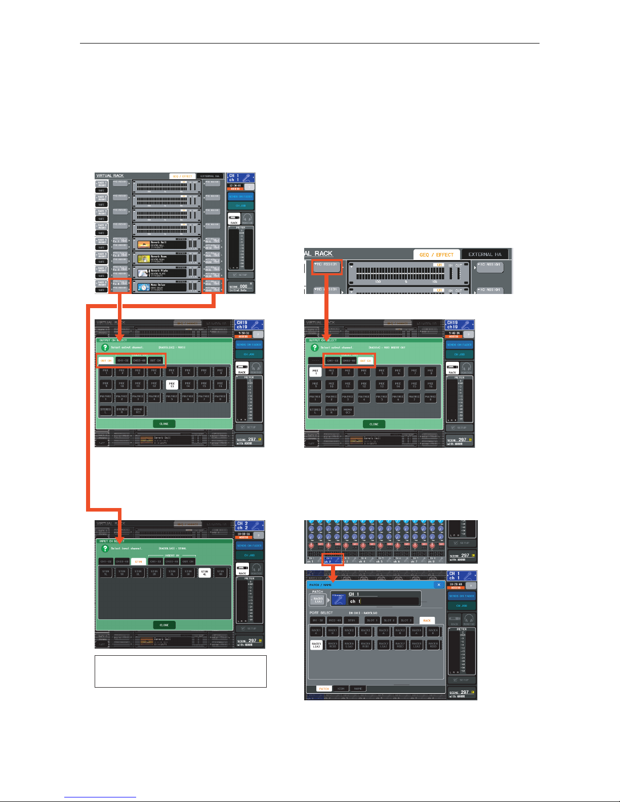
Effects. Mounting units in the virtual rack. . . . . . . . . . . . . . . . . . . . . . . . . . . . . . . . . . . . . . . . . . . . . . . . . . . . . . 4
Effects. Selecting, editing and storing the effect you want.. . . . . . . . . . . . . . . . . . . . . . . . . . . . . . . . . . . . . . . . . 5
Effects/graphic EQ. Assigning effects and GEQs. . . . . . . . . . . . . . . . . . . . . . . . . . . . . . . . . . . . . . . . . . . . . . . . . . 6
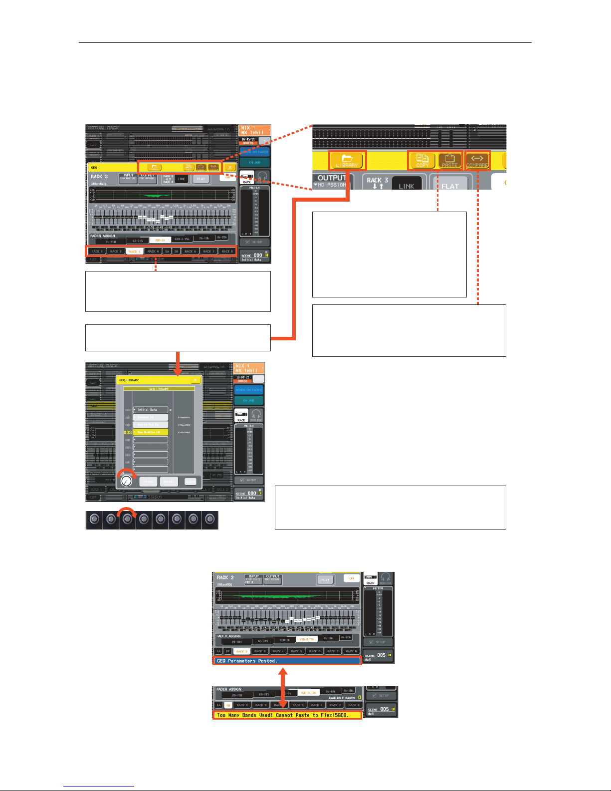
Graphic EQ. Selecting and editing the GEQs.. . . . . . . . . . . . . . . . . . . . . . . . . . . . . . . . . . . . . . . . . . . . . . . . . . . . 7
Graphic EQ. Copying, pasting, comparing and storing GEQ settings. . . . . . . . . . . . . . . . . . . . . . . . . . . . . . . . . . 8
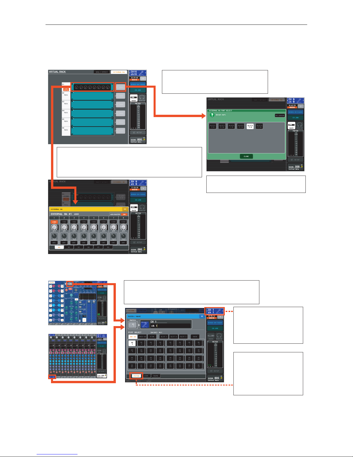
Connection and control of AD8HR remote head amp. . . . . . . . . . . . . . . . . . . . . . . . . . . . . . . . . . . . . . 9
Remote HA control. Remote HA setup 1.. . . . . . . . . . . . . . . . . . . . . . . . . . . . . . . . . . . . . . . . . . . . . . . . . . . . . . . 9
Remote HA control. Remote HA setup 2.. . . . . . . . . . . . . . . . . . . . . . . . . . . . . . . . . . . . . . . . . . . . . . . . . . . . . . 10
Connecting Studio Manager / M7CL Editor . . . . . . . . . . . . . . . . . . . . . . . . . . . . . . . . . . . . . . . . . . . . . 11
Editor setup; simple PC <-> M7CL via network port 1.. . . . . . . . . . . . . . . . . . . . . . . . . . . . . . . . . . . . . . . . . . . 11
Editor setup; simple PC <-> M7CL via network port 2.. . . . . . . . . . . . . . . . . . . . . . . . . . . . . . . . . . . . . . . . . . . 12
Editor setup; simple PC <-> M7CL via network port 3.. . . . . . . . . . . . . . . . . . . . . . . . . . . . . . . . . . . . . . . . . . . 13
MONITOR section. CUE buttons. Assigning a monitor output. . . . . . . . . . . . . . . . . . . . . . . . . . . . . . . 14
The back panel. Connections and outport delays. . . . . . . . . . . . . . . . . . . . . . . . . . . . . . . . . . . . . . . . 15
Using scenes. . . . . . . . . . . . . . . . . . . . . . . . . . . . . . . . . . . . . . . . . . . . . . . . . . . . . . . . . . . . . . . . . . . . . 16
Storing and recalling scenes. . . . . . . . . . . . . . . . . . . . . . . . . . . . . . . . . . . . . . . . . . . . . . . . . . . . . . . . . . . . . . . . 16
What is in a scene? . . . . . . . . . . . . . . . . . . . . . . . . . . . . . . . . . . . . . . . . . . . . . . . . . . . . . . . . . . . . . . . . . . . . . . 17
Recall safe.. . . . . . . . . . . . . . . . . . . . . . . . . . . . . . . . . . . . . . . . . . . . . . . . . . . . . . . . . . . . . . . . . . . . . . . . . . . . . 18
User defined keys. Programming user defined keys. . . . . . . . . . . . . . . . . . . . . . . . . . . . . . . . . . . . . . 19
Troubleshooting. . . . . . . . . . . . . . . . . . . . . . . . . . . . . . . . . . . . . . . . . . . . . . . . . . . . . . . . . . . . . . . . . . 20
© 2006 All rights reserved.

M7CL Quick Start Guide Part 2
3/20
Connect your M7CL just as you would an analog desk and
switch on. A real world example.
But try to be tidier than this!
Preparing the console before you start.
Before working on an analog console, it is customary to check that the console has been “set to zero”. This
normally means setting the gain to minimum, the EQ to flat, auxes to flat, group routing deselected, insert points
switched off, etc. Look at and check upwards of 1000 knobs! Because M7CL can memorize its settings, Yamaha
have provided a handy memorized scene (Scene 000) where the console is set to zero ready to start at the touch
of a key.
To recall Scene 000, press the up/down keys until “Scene 000” flashes in the SCENE field. Then press the
[RECALL] key.
Analog outputs. Start with L & R
connected to 15 (L) and 16 (R).
Network, word clock, MIDI, control, AES/EBU,
connections. Typically none are used!
Lamp connector.
Mic or line inputs.
Mono channels.
Optional external
PSU connector..
Mains power in and on/off switch.
Mic or line inputs.
Stereo channels.

M7CL Quick Start Guide Part 2
4/20
The virtual rack; effects and graphic EQ:
Effects. Mounting units in the virtual rack.
M7CL has an on-board virtual rack consisting of eight units. Any of the eight can be filled with 31 band graphic
EQ and the last four can be filled with SPX type multi-effect units. Any one unit can be a single 31 band GEQ or
2 x “flex 15” GEQ.
The default Scene 000 has four effects and four GEQ selected. There are always eight virtual rack units, even if
some are blank.
Only units 5-8 can be selected as effects. Any of the units can be GEQ or Flex15GEQ. To change the selected unit
from its current state to one of the other states, press the [RACK MOUNT] button. This brings up the RACK
MOUNTER pop-up window for the selected unit.
Press the [RACK] button in the Function Access Area to access the on-
board virtual effects rack. There are two tabs [GEQ/EFFECT] and
[EXTERNAL HA]. Press the tabs to change between the screens.
Use the RACK MOUNTER screen buttons to select a [BLANK], [31BandGEQ],
[Flex15GEQ], or [EFFECT]. Be sure to press [OK] to mount the effect. [X] will close the
pop-up without making the change.
This is the VIRTUAL RACK
GEQ/EFFECT screen for selecting and
controlling GEQ and effects.
This is the VIRTUAL RACK
EXTERNAL HA screen for controlling
external AD8HR head amps.
Press the [RACK MOUNT] button to
access the RACK MOUNTER pop-up.

M7CL Quick Start Guide Part 2
5/20
The virtual rack; effects and graphic EQ:
Effects. Selecting, editing and storing the effect you want.
From the main rack screen, press the center of the virtual rack mounted effect. This brings up the EFFECT
parameter pop-up.
To select another type of effect either; press the colored effect image to reveal the EFFECT TYPE pop-up or
press the [LIBRARY] button at the top of the pop-up and use the EFFECT LIBRARY pop-up. Change the effect
either by pressing the color image or by scrolling the library list with any of the encoders below the screen.
Edited effects can be stored in library locations 058 to 199. Positions 001 to 057 are read only locations. Positions
049 to 058 are reserved for future read-only effects. Note the best quality Rev-X reverbs are in 046, 047 and 048!
The parameters can be edited using the
encoders below. If there are more than one
row of parameters, touch a knob from the
row you want before using the encoders.
[LIBRARY] button or colored effect image.
Recall a new effect or store your edited
effect from this pop-up.
Recall a new effect from this pop-up.

M7CL Quick Start Guide Part 2
6/20
The virtual rack; effects and graphic EQ:
Effects/graphic EQ. Assigning effects and GEQs.
By default in Scene 000, the effects are prepatched. The sends are MIX 13-16, the returns are STEREO 1-4.
However these can be easily repatched if desired.
GEQ can be assigned to any insert point; INPUT, MIX, MATRIX or MASTER channel. Effects can be inserted or
fed from a mix, matrix or master out.
Please note; when choosing to return the effect to a different channel, the original routing to the STEREO input
channel is not lost. You should reassign the STEREO channel either as unassigned or to its associated HA.
Assign effect to ch. or ch. to effect
from these pop-ups.
✘
Effects also need a channel assigned to return to. By default in Scene 000, the STEREO channels are
selected, but these can be changed. To get to the INPUT CH SELECT pop-up, press the grey output
button beside the effect image or go from the Centralogic™ overview screen to the PATCH/NAME
pop-up where you can route the effect return, name it and give it an icon.

M7CL Quick Start Guide Part 2
7/20
The virtual rack; effects and graphic EQ:
Graphic EQ. Selecting and editing the GEQs.
From the main rack screen, press the virtual rack mounted GEQ. This brings up the GEQ pop-up.
From the GEQ pop-up, press the tab
below the GEQ image with the
frequency range you want to edit. For
example, [200-1k]. The tab will turn
white and the faders of the CentralogicTM
section will move to match the chosen
frequency range. Moving these faders
will edit the GEQ curve. Press different
tabs to access different frequency
groups.
Flat the whole EQ using the [FLAT]
button on the GEQ pop-up.
Different GEQs can be accessed from
the tabs at the bottom of this pop-up.
Flex15GEQ are selected and edited in
the same way. An AVAILABLE BANDS
count-down is displayed.
Zero individual Hz bands by pressing
the [ON] key above the fader.

M7CL Quick Start Guide Part 2
8/20
The virtual rack; effects and graphic EQ:
Graphic EQ. Copying, pasting, comparing and storing GEQ settings.
At the top of the GEQ pop-up are buttons for COPY, PASTE, COMPARE and LIBRARY.
You can paste any GEQ curve to a 31BandGEQ but only curves with less than 15 bands moved will paste to a
Flex15GEQ.
Pressing the [COPY] button stores
the displayed GEQ curve into a
temporary “copy buffer”. If
another GEQ is selected to the
screen, then pressing the [PASTE]
button will change that GEQ to
match the copied source.
If you copy a GEQ curve to the “copy
buffer”, you can change the curve and then
press the [COMPARE] button to alternate
between the two curves.
Use any encoder below the screen to scroll through
the 199 library locations. Then press the [RECALL] or
[STORE] button.
You can use the [RACK] tabs at the bottom
of the pop-up to move between different
GEQ units.
Press the [LIBRARY] button to store or
recall GEQ curves.

M7CL Quick Start Guide Part 2
9/20
Connection and control of AD8HR remote head amp:
Remote HA control. Remote HA setup 1.
Yamaha manufactures a remotely controllable mic head amp and AD (analog to digital) converter; the AD8HR.
The M7CL comes equipped to remotely control these head amps, but an extra AES Mini YGDAI Card is required
to receive the digital audio signals.
Turn off M7CL power before installing the Mini YGDAI card. Connect both audio and control cables. (See
manuals for pin configurations.) The M7CL will detect the card when it is powered on again.
Press the [RACK] button in the Function Access Area to access the on-board virtual effects rack. There are two
tabs [GEQ/EFFECT] and [EXTERNAL HA]. Press the tabs to change between the screens.
For each AD8HR that is connected there should appear a set of knob images. The +48V MASTER will light red if
the master is turned on on the AD8HR unit. Note AD8HR +48V are not governed by the [+48V MASTER ON/
OFF] button on the SETUP page of M7CL.
You can daisy chain the control
cable but each AD8HR must have a
separate AES multicore cable for the
audio.
M7CL supports all current Yamaha Mini YGDAI cards (not mLAN).
To receive AES digital audio from AD8HR, you need one of; MY8AE,
MY8AE96, MY8AE96S, or MY16AE (for 2 x AD8HR).
<M7CL> <AD8HR>

M7CL Quick Start Guide Part 2
10/20
Connection and control of AD8HR remote head amp:
Remote HA control. Remote HA setup 2.
To assign a remote HA to a M7CL channel, first select the input channel’s Centralogic™ overview or single
channel screen.
Now the channel HA encoder will operate the remote AD8HR. The panel brightness will affect the AD8HR LED
brightness too!
Choose the slot and channels that you
have connected the AD8HR to.
Push the grey button to the right of the
unit image to bring up the EXTERNAL
HA PORT SELECT pop-up.
Also if you push the unit image to get to the EXTERNAL
HA pop-up, you can set the AD8HR HPF. The gain can be
set from here, but if we assign the remote HA to a channel,
the channel HA control will also set gain and +48V.
From one of these screens, access the PATCH/NAME
pop-up. Press the SLOT tab and choose the slot
number to assign the remote HA to the M7CL channel.
You can move to the next
channel by pressing the
selected channel indicator,
or by pressing a channel
[SEL] key.
If the PATCH/NAME pop-
up opens on the ICON or
NAME page, you can
change to the PATCH page
by using the tabs at the
bottom of the pop-up.

M7CL Quick Start Guide Part 2
11/20
Connecting Studio Manager / M7CL Editor:
Editor setup; simple PC <-> M7CL via network port 1.
M7CL scene memories and libraries can be stored and edited away from the console in a suitably equipped
computer running M7CL Editor software. The computer can be linked to M7CL and data transferred between
the two via the Ethernet ports and also data synchronization is possible allowing the computer to act as a remote
controller for M7CL.
Access the NETWORK pop-up from the SETUP page. This gives; IP ADDRESS, GATEWAY ADDRESS, SUBNET
MASK and MAC ADDRESS. Note only Class C addresses are supported.
Software
Get the latest software downloaded free from;
http://www.yamahaproaudio.com/downloads/index.html
Hardware
Minimum requirements for the PC are;
- Windows XP. (Home or Professional)
- 800 MHz Intel Pentium/Celeron processor
- 256 MB available memory
- 30 MB hard disk space
- 1024 x 768 high color display
It is necessary to download;
1) Studio Manager Host program,
2) M7CL Editor, and
3) DME-N network driver.
and install them by following the onscreen instructions.
CAT-5 crossover cable

M7CL Quick Start Guide Part 2
12/20
Connecting Studio Manager / M7CL Editor:
Editor setup; simple PC <-> M7CL via network port 2.
To set the computer Internet Protocol (TCP/IP) properties;
[Windows] > [Control Panel] > [Network Connections] > [Local Area Connections] > [Properties]. Then select
‘Internet Protocol (TCP/IP)’ from the scroll list and click [Properties].
Set the M7CL network settings to the suggested default setting shown here in the NETWORK pop-up.
When the driver and IP settings are set, click [OK] to action the new settings.
IP address; match the first 3 sets of 3
numbers, but make the last number
different.
e.g. 192.168.000.003 (or 192.168.0.3)
Subnet mask; use ‘255.255.255.000’.
Default gateway; this would only be
used for connections between
different networks, leave it as the
default setting for simple connection.
Set the Protect No. to match the
MAC ADDRESS in the NETWORK
pop-up of the console.
Match the IP Address to the M7CL’s
IP ADDRESS (192.168.0.128 in this
example). These should be different
from your computer’s IP address.
Next, set up the DME-N Network Driver (called DME because it was developed for the YAMAHA DME
digital mixing engine series);
[Windows] > [Control Panel] > double click the icon to open the dialog box.

M7CL Quick Start Guide Part 2
13/20
Connecting Studio Manager / M7CL Editor:
Editor setup; simple PC <-> M7CL via network port 3.
Open Yamaha Studio Manager from the program menu or a shortcut. Open the File/Setup menu and select the
M7CL Editor in the left hand window and click [Add] to make it appear on the right.
When connection happens, the console and PC are “ONLINE” and the ONLINE indicator will go green. Any
changes on the M7CL or PC will be immediately copied to the other device, but only changes.
Pressing the [RE SYNC] button gives the option of matching the console setting to the PC or the other way.
Think carefully which direction to transfer before synchronizing; data can be lost if the wrong choice is made!
Synching from PC to console is like loading a new session over the console’s existing session.
Click [Set Default] so that you
don’t need to do this each time
you connect.
Next click the tab to open the MIDI Ports window. Check the boxes for ports you are using; ZONE 1. Click
[OK] and the M7CL Editor will appear in the Studio Manager window. Double click on the M7CL and the
Editor will open.
W
hen the M7CL editor screen first appears, click the File menu and go to System Setup. Here you must
assign the system ports to the ones you selected in a previous screen; ZONE 1 for both. If M7CL has an
A
dministrator password, enter it here for full access. Click [OK] to apply and close the window.

M7CL Quick Start Guide Part 2
14/20
MONITOR section. CUE buttons. Assigning a monitor output.
Cueing a channel will send its audio signal to the CUE bus and meter the channel in the Function Access Area.
The audio will be sent to the headphone output under the front panel. Press the [MONITOR] headphone symbol
to access options for the monitor setup.
Note; [CUE] > [SEL] link is in SETUP>USER SETUP.
By default, the MONITOR section is fed by
STEREO L/R and these signals are sent to
the headphone output. (Found under the
front panel.) Cueing a signal interrupts this
and replaces the cued signal.
As well as the headphones, the MONITOR
section can output via an OMNI socket on
the rear. This patching is also accessed
from the MONITOR pop-up.
Using the SOURCE SELECT buttons
in the MONITOR section can switch
off the default STEREO L/R feed to the
monitor bus or replace it with one of
the other outputs or a ST IN.
The PHONES LEVEL LINK makes the
headphone level control come after
the MONITOR LEVEL pot on the
surface. This link can be broken,
which is especially useful for monitor
mixing.
Press here for
cue clear.

M7CL Quick Start Guide Part 2
15/20
The back panel. Connections and outport delays.
Each output, including the slots and AES, has a delay, polarity and attenuator adjustment available from the
OUTPUT PORT pop-up. This is found via the [SETUP] and [OUTPORT SETUP] buttons.
Each input channel has a balanced XLR input
to the high quality mic preamp. This includes
the STEREO input channels
2TR OUT DIGITAL; in addition to the 16 analog OMNI
OUT, there is one AES/EBU digital output (two
channels in one connector).
REMOTE; this carries remote control information to
Yamaha’s AD8HR remote head amps.
WORD CLOCK; use these connections for other digital
audio devices that are not word-clocked through the
audio connection.
MIDI; the console can generate or receive MIDI
program changes and MIDI control data changes via
these ports.
NETWORK; this Ethernet connector is for connecting
to a computer running Studio Manager/M7CL Editor.
OMNI OUT; there are 16 assignable analog outputs. These can be assigned to any MIX bus, matrix,
master, monitor, or direct output. They cannot be insert sends.
Note; this is the best screen to view output
patching.
Note; push the knob and turn at the same time
to get ‘fine resolution’.

M7CL Quick Start Guide Part 2
16/20
Using scenes:
Storing and recalling scenes.
M7CL can store 300 scene memories or snapshots. In addition to the 300 numbered memories, there is the
default read only Scene 000 and also the ‘current console settings’ which are either the same as a scene or an
edited version of a scene. These are in a special memory buffer which is retained in case of power failure.
When the console parameters are edited to a position you want to keep, press the [SCENE MEMORY] up/down
keys to choose a numbered location for the new scene.
The chosen number will flash. Next press the [STORE] key and the SCENE STORE keyboard pop-up will
appear. This lets you name the scene and provides extra space for a comment or longer scene name.
Press the [STORE] button (on screen) or the [STORE] key (on desk), and the scene is stored. The scene number
shows in the Function Access Area and the goes out until another desk change is made.
To recall a scene, use the up/down keys to find its number and then press the [RECALL] key. The desk will reset
itself to the chosen scene. You cannot recall “empty scenes” with no data stored in them. If you want to start
from a fresh clean desk, choose Scene 000.
If you press the SCENE field, you can view the SCENE LIST. From the list, you can store and recall but also CUT,
COPY, INSERT, CLEAR and PASTE single or multiple scenes to organize your scene list.
Scene 000 is read only. When it is
edited the yellow appears.
Flash!
Flash!
Flash!
SCENE field

M7CL Quick Start Guide Part 2
17/20
Using scenes:
What is in a scene?
When a scene is stored, all the items from the “Included” column are stored to the scene memory.
The items in the “not included” column are saved in a global memory (except mechanical pots) and do not
change when scenes are recalled. They are remembered when the desk is powered down and will be recalled at
power on.
When a scene is recalled, it is possible to select certain parameters not to be recalled. This is called to RECALL
SAFE a parameter. Access to the RECALL SAFE MODE pop-up is from the [CH JOB] button in the Function
Access Area.
Included in scene recall
- Head amp (level, +48V, φ)
-Name/icon
- Routing (Input, Output, Insert, Direct, Monitor,
Cascade, Rack)
- Insert (on/off, position)
- Direct out (on/off, position, level)
-EQ(all parameters inc HPF)
-ATT(digital attenuator)
-Dynamics1(all parameters)
-Dynamics2(all parameters)
- MIX sends (bus setup, on/off, level, pre/post)
- Pan/balance (position Stereo/ Mono/LCR)
-DCA(assignment, level)
- Mute group (assignment, on/off)
-Faders
-Rack(all parameters)
- Rear panel input to talkback routing (and levels
in MONITOR screen)
-Focus
- Cross fade (on, time)
Not included in scene recall
- User defined keys
- Preferences
- Monitor level pot
- Headphone level pot
- Front panel talkback level pot
- Brightness controls
-OUTPORTsettings(except routing)
-MIDIsetup
- Word clock
- Master +48V
- CUE pop-up (PFL trim inputs, DCA trim, PFL trim
outputs)
- MONITOR pop-up (levels, source on/off, mono,
link)
- Oscillator (all parameters)
- Safe assignments (mute, recall)
- Passwords
- Screen page or pop-up
- Sends on fader selected/channel
- Metering point selection
- External HA to slot assignment
There are 302 memories; Read only
Scene 000, 300 user scenes and the
current edited scene.

M7CL Quick Start Guide Part 2
18/20
Using scenes:
Recall safe.
To prevent a channel or parameter changing at a scene recall, the channel or parameter can be made “safe from
recall”. To access the RECALL SAFE MODE pop-up, press the [CH JOB] button, then the [RECALL SAFE]
button. Recall safe settings are global to all scenes, including Scene 000.
Individual or all channels can be made safe by selecting [SET BY SEL] and then pressing their [SEL] keys and
the [SAFE] button. The channel will turn on the screen. It is possible to make safe only certain
parameters of a channel. For example; the EQ of the guitar channel. This is termed PARTIAL SAFE. Partial safe
channels are . There is only one indication but there are many partial safe options.
To “partial safe” a channel from the RECALL SAFE MODE pop-up, select the channel then press buttons from
the menu. The [ALL] button will go out. To partial safe all selected input channels with the same parameters, be
sure to press the [APPLY TO ALL INPUT] or [APPLY TO ALL OUTPUT] button before selecting from the menu.
Input partial safe menu Output partial safe menu
Pressing the [GLOBAL RECALL SAFE]
buttons will prevent the non channel
specific parameters from being
changed by recall. Note they are not
locked from being edited; that is a
guest access function. Green means
safe. Black means recallable.
green
blue

M7CL Quick Start Guide Part 2
19/20
User defined keys. Programming user defined keys.
There are 12 user defined keys on M7CL. These are programmable shortcut keys; they can replace a screen
press or cause some other action. They come pre-programmed with some examples but can be user defined
from a menu in the SETUP page.
Now you can go to the screen you wish to access from the user defined key. When on that screen, press and hold
the key for a couple of seconds to program it. Now pressing that key will take you straight to the screen from
any other starting place.
To access the USER SETUP pop-up,
press the [SETUP] button in the
Function Access Area. Then press the
[USER SETUP] button. If this does not
show the USER DEFINED KEYS, use
the tab at the bottom of the pop-up.
The pop-up shows the action of the pre-
programmed default keys.
To change a key, press on the
screen key to give the USER
DEFINED KEY SETUP pop-up.
To bookmark a particular screen,
choose [PAGE CHANGE] in column 1
and [PAGE BOOKMARK] in column 2.
Scroll up/down with the screen buttons
or use the encoders below the screen.
Push-click to move to the next column.

M7CL Quick Start Guide Part 2
20/20
Troubleshooting.
I can’t get +48V to work.
☞+48V is switched on/off in the HA pop-up, but remember there is also a master switch on the SETUP
page. This is not covered by scene recall.
The aux sends are in big steps when I turn the encoder;
I need a finer control on my output delays;
☞Try pushing and turning at the same time. This gives a fine resolution mode.
When I press the navigation keys, the screen changes but the faders don’t copy to the chosen bank.
☞This is a feature often used to keep access to the DCA masters even when other banks are chosen. Press
and hold the navigation key until it flashes. Now that fader bank is locked even though the screen
information changes. To undo, just press and hold again.
I’ve recalled Scene 000 but some faders and other things have not reset to zero.
☞Are there any recall safes set? This means that aspects of Scene 000 may not have been recalled because
they are safe from recall changes. Check in CH JOB > RECALL SAFE. Clear all of these and recall Scene
000 again.
The fader has stopped working!
☞Is SENDS ON FADER active; this means you are pushing up an aux send and not the channel master. You
can tell easily when you are in sends on fader mode because all the green [SEL] indicators are on except
the selected channel. In normal mode, the [SEL] indicators are off and the selected channel is lit.
☞Have you ‘moved’ a channel or changed the patch or both? Check the patch and the channel name/
number to confirm they are what you expect.
Where are the output delays?
☞They are outport delays, found in the OUTPUT PORT pop-up via the SETUP page.
I’ve checked and checked all the settings and still the Studio Manager software says the ports are
unavailable! My colleagues computer connects fine.
☞You need to use a CAT-5 crossover cable. Some computers detect and fix this problem automatically so
that’s why other computers work and yours doesn’t.
Where can I find out more information?
☞You can download the manual from;
http://www.yamaha.co.jp/manual/english/result.php?div_code=pa&model=M7CL&cat_code=&div_code=pa
Other manuals for M7CL StageMix V1.5
19
Table of contents
Other Yamaha Music Mixer manuals

Yamaha
Yamaha UW500Plus User manual

Yamaha
Yamaha MG12/4 User manual

Yamaha
Yamaha MX12/4 User manual

Yamaha
Yamaha M2500 User manual

Yamaha
Yamaha DMP7 User manual

Yamaha
Yamaha 03D Instruction Manual

Yamaha
Yamaha MM1242 User manual

Yamaha
Yamaha EM-1400 User manual

Yamaha
Yamaha RIVAGE PM10 User manual

Yamaha
Yamaha MC2410M User manual