60H5E11
GEN
INFO General information
1-3
Parts, lubricants, and sealants
Use only genuine Yamaha parts, lubricants,
and sealants or those recommended by
Yamaha, when servicing or repairing the
outboard motor.
Under normal conditions, the lubricants men-
tioned in this manual should not harm or be
hazardous to your skin. However, you should
follow these precautions to minimize any risk
when working with lubricants.
1. Maintain good standards of personal and
industrial hygiene.
2. Change and wash clothing as soon as pos-
sible if soiled with lubricants.
3. Avoid contact with skin. Do not, for ex-
ample, place a soiled rag in your pocket.
4. Wash hands and any other part of the body
thoroughly with soap and hot water after
contact with a lubricant or lubricant soiled
clothing has been made.
5. To protect your skin, apply a protective
cream to your hands before working on the
outboard motor.
Safety while working
To prevent an accident or injury and to ensure
quality service, follow the safety procedures
provided below.
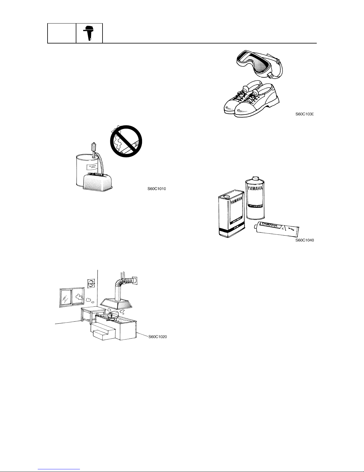
Fire prevention
Gasoline is highly flammable.
Keep gasoline and all flammable products
away from heat, sparks, and open flames.
Ventilation
Gasoline vapor and exhaust gas are heavier
than air and extremely poisonous. If inhaled
in large quantities they may cause loss of
consciousness and death within a short time.
When test running an engine indoors (e.g., in
a water tank) be sure to do so where adequate
ventilation can be maintained.
Self-protection
Protect your eyes by wearing safety glasses
or safety goggles during all operations involv-
ing drilling and grinding, or when using an air
compressor.
Protect your hands and feet by wearing pro-
tective gloves and safety shoes when neces-
sary.